Micom uv testing ebook 2019 final
Bạn đang xem bản rút gọn của tài liệu. Xem và tải ngay bản đầy đủ của tài liệu tại đây (4.78 MB, 47 trang )
PRACTICAL GUIDE TO
UV TESTING
MICOM
LABORATORIES
INC.
Founded in 1999, Micom Laboratories Inc. is an established third
party independent laboratory offering products and material testing services. With a proven track record of helping customers
succeed, we specialize in providing complete test services and
expertise for today’s complex offerings.
With years of specialized technology testing expertise, in-depth
experience and absolute commitment to customer care, our team
of experts does more than simply test your products. Micom
Laboratories Inc. strives to deliver outstanding value to our diverse customer base.
Our philosophy is to provide the highest quality services at valuebased costs.
Our measure of success is our long-term client partnerships.
Micom Laboratories Inc. is committed to providing rapid turnaround time, value based pricing, technical assistance, key account management and accurate timely reporting. We are partners with our clients to improve the quality of their products and
brand image.
Using proven processes and quality procedures in its specialized
lab, Micom Laboratories staff delivers the end results our customers need – products that meet all necessary requirements to ship
in order to ship them around the globe. This frees them from
costly and time-consuming testing and allows them to focus on
their essential engineering and business issues.
Today Micom Laboratories has a 15 000 square feet test facility,
in Montreal, Canada. We offer a wide range of test services all related to material and product testing.
If you have any questions about UV Testing and would like to
speak to one of our material testing specialists, we invite you
to contact us today at 1 (888) 996-4266.
It will be our pleasure to answer your questions.
COPYRIGHT © 2017 BY MICOM LABORATORIES |UV TESTING LABORATORY |1-888-996-4266 | WWW.MICOMLAB.COM
i
CHAPTER 1
ACCELERATED AGING
Accelerated aging is a broad type of testing that uses amplified adverse conditions to increase the
rate of aging of materials and products. Amplified adverse conditions can be environmental in nature
(such as sun, heat, cold, salted water, vibrations, etc.) or simulate accelerated wear and tear or a
combination thereof. The goal is to estimate quickly the products and materials expectable service
life or to understand unexpected field failures.
The process of accelerated aging of products and materials can be accomplished in various ways
depending on the type of material or product being tested, the intended use as well as the ambient
conditions present while using the material or product.
COPYRIGHT © 2017 BY MICOM LABORATORIES |UV TESTING LABORATORY |1-888-996-4266 | WWW.MICOMLAB.COM
2
Among the most popular types of accelerated aging tests are:
•
UV testing
•
Corrosion testing
•
Heat aging testing
•
Temperature and humidity testing
•
Thermal shock testing
•
Functional cycling
When performing this type of testing it is important to have a good understanding of the product characteristics, the normal use conditions, what constitutes a foreseeable abuse and what is the product’s
life expectancy. To have a good assessment of the product’s performance and be able to predict how
it will fare in the future, we need to be careful not to expose a product to conditions that could cause
abnormal aging processes to occur (i.e. avoiding supplying our sample with an activation energy for
a specific aging reaction that would not occur naturally in real life conditions). Accelerated aging is
as much a science as an art.
Field exposure can lead to many failure types such as:
•
Discoloration (fading) and color change
•
Cracking
•
Corrosion
•
Flaking
•
Wear
Accelerated aging is often a combination of various environmental stresses such as UV exposure,
corrosion, temperature and relative humidity variations as well as numerous pollutants (such as
Ozone, NOx, SxO, etc.,). Since these aging mechanisms will often compound themselves synergistically, we will also combine some test methods at our Testing Lab. For example the ASTM D5894 ,also
know as Cyclic Salt Fog/UV Exposure of Painted Metal Test, combines cyclic corrosion and UV exposure in one test. The fact that applications can be so diverse, it is often impossible, even given today’s technology, to simulate all aging parameters with all their intricacies at once. From a development standpoint it can also be better to simulate a limited amount of parameters at once so that each
aging mechanism can be isolated and evaluated by itself.
COPYRIGHT © 2017 BY MICOM LABORATORIES |UV TESTING LABORATORY |1-888-996-4266 | WWW.MICOMLAB.COM
3
REAL WORLD APPLICATION
Accelerated aging is just like cooking a turkey
You forgot the “In laws” are coming tonight for Thanksgiving. You have a 20 pounds frozen turkey in
your hands, you look at the clock on the wall and realize you have 3 hours until dinner. While you
would have let the turkey thaw overnight and would have left it in the oven for about 5 hours you now
have to cook it on an “accelerated basis” to make up for your error. How about setting your oven at
“self cleaning” and cook the turkey for some time at that temperature? Simply because you will end
up with a charred turkey on the outside still frozen on the inside.
Accelerated aging, including corrosion and UV testing are just the same. If your aging process is too
aggressive, you will get results that are just like that frozen turkey; not what you wanted. This is because you gave your material an activation energy that is not realistic compared to what it will experience in real life.
COPYRIGHT © 2017 BY MICOM LABORATORIES |UV TESTING LABORATORY |1-888-996-4266 | WWW.MICOMLAB.COM
4
BASIC RULES
TEMPERATURE
There are basic rules to be followed in all aging testing procedures. With the exception of freeze-thaw
cycles that assess the impact of phase changes, all aging processes increase as a function of the
ambient temperature. This acceleration process is governed by Arrhenius’s law:
k (rate of change) = A exp (-E/RT)
where E = activation energy
A = pre-exponential factor
T = absolute temperature
R = gas constant
In layman’s terms; any chemical reaction will double its rate with each 10 °C increase. This is why corrosion and UV aging, for example, are both done at temperatures above room temperature. Conversely excessive temperature exposure is not recommended. Beyond a certain temperature point,
high levels of activation energy will cause molecules in the tested material to respond and cause
chemical reactions to take place that would not naturally occur even over long periods of time or extremely adverse conditions.
In addition in many accelerated aging processes, organic molecules experience asymptotic behavior
(i.e. beyond a certain temperature there is no significant gain; only risk).
COPYRIGHT © 2017 BY MICOM LABORATORIES |UV TESTING LABORATORY |1-888-996-4266 | WWW.MICOMLAB.COM
5
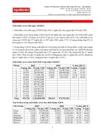
Figure #1a: Arrhenius’s law – accelerated aging curves
Arrhenius’s law is general in nature and it assumes the general case where the aging rate doubles
every 10ºC increase. This ideal case would correspond to curve Q10=2 above. If you want to age
your products at a temperature of 45 ºC, for example, you would need a 10 weeks aging process to
simulate one year of real life aging.
The accelerated aging factor is not always “2”. If the aging factor is known then the simulation can be
adjusted accordingly. For example should it turn out that the material being tested has an accelerated aging factor of 3 (q10=3 above); for the same aging temperature of 45 ºC, the number of normal
weeks of aging would be 4 instead of 10.
COPYRIGHT © 2017 BY MICOM LABORATORIES |UV TESTING LABORATORY |1-888-996-4266 | WWW.MICOMLAB.COM
6
DARK CYCLES
In some instances of aging processes there is one of multiple primary reactions that can compete or
promote each other. There are also secondary reactions that can have a significant bearing on the final results. In some cases both reaction types can occur simultaneously. Also sometimes the secondary reaction can only occur in the absence of the primary reaction. This secondary reaction can generate intermediates that will react once the primary reaction resumes. It is important to provide a
“dark” cycle that stops the primary aging process to leave room for secondary process. For example,
in many UV aging test methods there is a portion of the exposure that occurs without any UV bombardment. The same is true for corrosion testing where the most evolved test methods are cyclic in
nature with a “dark cycle” (i.e. for a certain period of time there is no corrosive agent at the materials
being tested). Most advanced aging test procedures include dark cycles of some sort.
WATER
Water is often used in synergistic aging. In some cases water is directly involved in the chemical reaction occurring in the aging process. In other cases water can have a mechanical contribution such as
erosion or cooling. Furthermore, it can sometimes act as a lens locally concentrating the incident light
or it can simply be used to wash off the samples substrate to allow for a dark cycle (e.g. cyclic corrosion or rain cycle in weathering testing).
ONCE THE AGING PROCESS IS OVER
Once the aging process is completed physical/mechanical measurements need to be made on the
samples to assess whether or not product properties were modified or adversely compromised compared to the unexposed product. Taking measurements while the aging process is occurring can be
extremely helpful:
• Saves time if early failures are observed
• Provides a better understanding of material behavior
• Allows for a better comparison and final test results interpretation when tested side-by-side to a reference product with known characteristics
Micom Laboratories Inc. is an established third party independent laboratory offering products
and material testing services. If you have any questions about UV Testing and would like to speak
to one of our material testing specialists, we invite you to contact us today at 1 (888) 996-4266.
It will be our pleasure to answer your questions.
COPYRIGHT © 2017 BY MICOM LABORATORIES |UV TESTING LABORATORY |1-888-996-4266 | WWW.MICOMLAB.COM
7
CHAPTER 2
WHY TEST FOR ACCELERATED AGING?
Ultraviolet (UV) testing from an accelerated aging perspective finds its roots in photochemistry. This
part of chemistry studies light as an energy source to induce chemical reactions (i.e. light is used to
provide the required activation energy so that one or more chemical reaction start occurring). Photochemistry deals almost exclusively with organic molecules (i.e.: carbon based molecules). Typical examples of organic molecules include polymers and coatings that are all susceptible to sun degradation over a certain period of time, as well as most of all living tissues: plants, trees, human’ skin, etc.,
Figure #1, below, shows the complete spectrometric spectrum. Of this spectrum only minuscule portion is visible to the human eye: from 390 to 700 nanometers (nm). The UV spectrum goes from 10 to
400 nm. Most spectrophotochemical reactions are promoted with wavelength between 200 nm and
400nm as well as in the visible from 400 to 700nm.
COPYRIGHT © 2017 BY MICOM LABORATORIES |UV TESTING LABORATORY |1-888-996-4266 | WWW.MICOMLAB.COM
8
Figure #1 Spectrophotometric spectrum. Source: www.austincc.edu
Only specific functional “sites” of organic molecules will react at very specific wavelength corresponding to site’s specific resonance energy levels. These sites are called “Chromophores”. If available, t
he chromophores will absorb radiant energy corresponding to the vibration levels of their valence
electrons. These excited electrons will then be promoted to specific higher energy levels (orbitals)
where they become much more reactive (activated complex) and are likely to get involved in chemical reactions that would not occur under normal conditions. Theses reactions could involve a mixture
of the following:
• Bond to other molecules close by (isomerization)
• Bond to other active sites on the same molecule (rearrangement)
• Breakage of the molecular chain (photolysis).
Most typical photochemical sequences occur in phases:
• Absorption of light energy exciting one or more chromophore on a molecule
• Primary photochemical reaction of the excited Chromophore
Secondary chemical reactions occurring as a result of the presence of the activated complexes generated by the primary reaction. These secondary reactions do not require light as activation energy
(Dark cycle).
COPYRIGHT © 2017 BY MICOM LABORATORIES |UV TESTING LABORATORY |1-888-996-4266 | WWW.MICOMLAB.COM
9
REAL WORLD APPLICATION
Why do Fireflies shine?
Despite its scary technical name; everybody has witnessed naturally occurring photochemistry phenomenon. A common example is the firefly. Fireflies produce an electronically excited enzyme called
“luciferin” emitting light as a result of a peroxide function decomposition through an enzymatic reaction.
This “bioluminescence” phenomena is actually essential to the fireflies mating process. While the
male is flying it emits flashes of light at a given frequency. The females, while they remain stationary,
flash a response which orients the males in the proper direction and the signaling process keeps iterating until the mates are united. Different firefly species will differentiate from each other because of
the signal frequencies used by each species.
Photosynthesis is another important photochemistry based process; no light, no plants.
Source: www.farmersalmanac.com
COPYRIGHT © 2017 BY MICOM LABORATORIES |UV TESTING LABORATORY |1-888-996-4266 | WWW.MICOMLAB.COM
10
UV EXPOSURE AND SUNLIGHT
Everybody is familiar with terms such as “Ozone layer hole” (figure #2), “SPF”, “Skin Cancer” and the
importance of protecting our skin when being outdoors for some period of time. What is the technical
explanation behind all this? The sun emits light and a significant portion of this light is in the ultraviolet
domain.
The spectrum of solar radiation on Earth is shown on the next
page in figure #3. The spectrum’s yellow and red portion added
together amount to the total solar emissions. The part in yellow
never makes it to the Earth’s surface as it gets filtered by the
ozone layer, hence the importance of NOT having an “Ozone
Hole”.
Figure 2. Image of the
largest Antarctic ozone hole
ever recorded (September
2006), over the Southern
pole
The CO2 and water present in the atmosphere also absorb a portion of the U.V. Emission’s spectrum (see figure #3 for absorption
bands). As the Ozone Layer becomes thinner, higher amounts of
ultraviolet radiations and shorter, higher energy wavelengths, are
not filtered out anymore thus having a more deleterious and
faster effect not only on us but on everything outdoors or exposed to sun through a window. The shorter, more energetic
wavelengths, will also attach chromophores that would not have
reacted years ago as those short wavelengths were not present
either at all or were only present in negligible quantities. This also
explains why you need more skin protection if you travel to very
high altitudes areas: there is less atmosphere to filter the UV radiations.
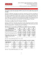
On the next page, Figure #3 shows the difference between the emission solar spectrum and what effectively gets to the planet’s surface. Infrared radiations that get to the earth’s surface are felt as heat
and do not have any deleterious effects on organic molecules. In other terms these radiations are not
harmful. As discussed earlier, most spectrophotochemical reactions will be stimulated with wavelength between 200 nm and to 700nm. Because of their shorter wavelengths and higher energy; the
ultraviolet radiations will break down stronger chemical bonds. The UV spectrum is split in four wavelength ranges:
UV A
UV B
UV C
Vacuum UV
320-400 nm
290 -320 nm
200-290 nm
10-200 nm
COPYRIGHT © 2017 BY MICOM LABORATORIES |UV TESTING LABORATORY |1-888-996-4266 | WWW.MICOMLAB.COM
11
Figure #3: Spectrum of Solar
Radiation on Earth
(source:
www.Wikipedia.org)
As can be seen in figure #4 below, UVc radiations (200-290 nm) are strongly absorbed by earth’s
ozone layer. There is very little UVb (290-320 nm) and the bulk of the UV radiations is in the UVa region. It is important to understand the UV distribution on earth since it will help you decipher what is
the best simulation possible for your application.
It should be noted that despite the small amount of UVbs present at Earth’s surface, because of their
higher energy, their presence should not be neglected.
Figure #4: UV and Visible sun spectrum
on earth.
(Source: Sunlight, Weathering & Light
Stability Testing.
Q-Lab, Technical Bulletin LU-0822)
COPYRIGHT © 2017 BY MICOM LABORATORIES |UV TESTING LABORATORY |1-888-996-4266 | WWW.MICOMLAB.COM
12
Typically, saturated and mono-unsaturated molecules (e.g.: waxes, some oils) will be excited at wavelengths below 190 nm. Poly-unsaturated molecules and aromatic compounds will react at wavelengths between 190-380 nm (most polymers, most living tissues). Colors in colored materials will react with light exposure within a range of 380- 780 nm.
Chromophore
max(nm)
Anexampleofcompound
H2O
183
C-CaC-H.CH4
CCA170,173
C-X,CH3OH,CH3NH2,CH3I
180-260,187,215,258
C=C,H2C=CH2
160-190,162
H2C=CH-CH=CH2
217
C=O,H-CH=O
270,170-200,270,185
H2C=CH-CH=O
328,208
C-N
190,300
N=N
340
C=S
500
NO2
420-450
N=O
630-700
Table 1: Chromophores examples and their resonance wavelengths.
On the next page, Figure #5 shows the difference between the UV intensity of direct sunlight and sunlight exposure through glass. A quick look at the two curves might give the impression there is not
much difference between direct sunlight and sunlight through glass. Did you ever catch a sunburn
behind a window glass? Obviously not! Should you take a closer look you would note that the overall
light intensity is about 15% higher for outdoor exposure.
COPYRIGHT © 2017 BY MICOM LABORATORIES |UV TESTING LABORATORY |1-888-996-4266 | WWW.MICOMLAB.COM
13
Figure #5: Direct sunlight and
sunlight through glass
(Source: Sunlight, Weathering &
Light Stability Testing. Q-Lab,
Technical Bulletin LU-0822)
However this known fact and the lower light intensity does not explain why one cannot get a sunburn
behind a window glass. The reason lies in the spectrum’s UV segment. First of all because these
wavelengths being shorter are much higher in energy. Furthermore, in that portion of the emission
spectrum, the direct sunlight curve shows light intensities that are many times the light intensity of the
sunlight through window glass curve. We will come back to the importance of the curve differences
later on when we discuss which test conditions should be used.
Figure #5a: Direct sunlight
and sunlight through glass;
UV region.
(Source: Sunlight,
Weathering & Light
Stability Testing. Q-Lab,
Technical Bulletin LU-0822)
COPYRIGHT © 2017 BY MICOM LABORATORIES |UV TESTING LABORATORY |1-888-996-4266 | WWW.MICOMLAB.COM
14
REAL WORLD APPLICATION
Can someone get a sunburn through a vehicle window while driving?
According to Huffington Post Canada,“Truck driver Bill McElligott, 69, has unilateral dermatoheliosis,
according to The New England Journal of Medicine. Essentially, ultraviolet A (UVA) rays transmitted
through the window of his delivery truck have severely damaged the skin on the left side of his face
during the 28 years he has spent driving on the job.”
If you look at Figure #5 on the previous page, it shows there is a difference between a direct sun exposure and an exposure to sun through glass. The intensity difference when you are behind a window is
probably sufficient so that we don’t get a “standard” sunburn. However, figure #5 clearly shows there
is still a significant amount of UVAs and some, higher energy – more detrimental, UVBs.
Source: />
COPYRIGHT © 2017 BY MICOM LABORATORIES |UV TESTING LABORATORY |1-888-996-4266 | WWW.MICOMLAB.COM
15
SOLAR EXPOSURE VARIATIONS
CHEMISTRY OF THE ENVIRONMENT
The actual environment where a product is used is often difficult to completely simulate as there are
too many aging processes happening simultaneously. Parameters such as ambient relative humidity,
rain, pollution, altitude and geographical position, average temperature, hours of exposure and many
others will impact the extent and specific aging mode. We also have to consider additional aging
processes that synergistically compound their aging impacts such as corrosion, freeze-thaw cycles,
abrasion, etc.,
Atmospheric pollution can also be a contributing factor. For instance, in principle, a dense smog
should limit the amount of sunlight that gets to the materials surface. Conversely if the chemicals present in the smog are photo sensitive, their activated complexes might react with the materials surfaces and initiate a degradation process that would not have occurred otherwise. Ozone exposure
can also damage significantly materials surfaces.
LOCATION
Solar radiations can vary significantly from year to year and from location to location. Below is a map
of the yearly regional sum of irradiance. The spread can be as wide as five folds.
Figure #6: Yearly sum of global irradiance
COPYRIGHT © 2017 BY MICOM LABORATORIES |UV TESTING LABORATORY |1-888-996-4266 | WWW.MICOMLAB.COM
16
SO WHY UV TESTING?
In summary, Sunlight exposure either direct or through glass can have deleterious impacts on carbon
based materials such as coatings, polymers, textiles and many others. The damages vary and can
include among others:
• Chalking
• Cracking
• Loss of physical properties
• Peeling
• Blistering
• Fading
• Color Change
Laboratory UV testing allows for faster, more reproducible, systematic and reliable results. As outlined above, there are no techniques that can take all of the potentially contributing factors. Most techniques will compound UV exposure with temperature and water (spray, dew, relative humidity).
Because the amount of light per hours per surface unit is controlled (irradiance) it is possible to calculate, for a given region, the approximate amount of years of real life exposure an actual test sample is
being exposed too. This process is called the “time compression factor”.
Micom Laboratories Inc. is an established third party independent laboratory offering products
and material testing services. If you have any questions about UV Testing and would like to speak
to one of our material testing specialists, we invite you to contact us today at 1 (888) 996-4266.
It will be our pleasure to answer your questions.
COPYRIGHT © 2017 BY MICOM LABORATORIES |UV TESTING LABORATORY |1-888-996-4266 | WWW.MICOMLAB.COM
17
CHAPTER 3
HOW TO TEST ACCELERATED AGING?
HOW IS LABORATORY UV TESTING DONE?
There are three main types of laboratory UV test equipment. The main difference between them is the
light source used to generate the UV Visible emission spectrum. The three light source types are:
ã Carbon arc
ã Xenon arc
ã Fluorescent lighting
COPYRIGHT â 2017 BY MICOM LABORATORIES |UV TESTING LABORATORY |1-888-996-4266 | WWW.MICOMLAB.COM
18
CARBON ARC
Carbon arc was actually the first light source to be used for UV exposure testing. This light source is
based on an older technology: an electric arc between two carbon electrodes that were being progressively consumed and producing a light spectra. Despite the fact that equipment manufacturers
don’t support carbon arc equipment anymore, it is still used namely by the Japanese automotive industry for legacy reasons; they have a lot of historical data based on that technique so they want to
keep comparing apples to apples.
Figure #8: Carbon arc emission
spectrum
(Source: From : Sunlight,
Weathering & Light Stability
Testing. Q-Lab, Technical
Bulletin LU-0822)
Figure #8 above compares the enclosed arc to the sun emission spectrum. It can easily be seen that
for the carbon arc a large portion of the spectrum is missing while the emission intensity is extremely
high in some specific areas. Depending of the specific chromophore(s) a given material has and its
overall molecular structure the product might “over react” if one of its bond happens to have an absorption frequency that coincides with the emission peaks or it might not react at all if its resonance
frequencies do not coincide with the carbon arc emission bands . So one could get a “false” positive
or a “false” negative which leads to a poor simulation and consequently to the wrong conclusions.
Sunshine carbon arc, another carbon arc type, also has a really high intensity peak around 385 nm
and has an emission spectra that goes well within the UVc realm that will only be present in outer
space. As the higher energy frequencies are not present on earth it could degrade products using
certain chemical reactions that would not realistically occur on earth even if the material was exposed
for a century.
COPYRIGHT © 2017 BY MICOM LABORATORIES |UV TESTING LABORATORY |1-888-996-4266 | WWW.MICOMLAB.COM
19
XENON ARC
Xenon, a noble gas, is a chemical element (Xe). It is a colorless, heavy gas (66 times the molecular
weight of hydrogen, H2). Xenon has numerous very specific chemical characteristics, namely its
chemical “inertness”. Xenon is used in photographic flashes, in high pressure arc lamps for motion
picture projection, and in high pressure arc lamps to produce ultraviolet light.
Xenon arc units use a xenon in a precision gas discharge lamp in a sealed quartz tube. To obtain a
better match with the sun emission spectrum, the xenon arc must be filtered using specific filter combinations. Depending on whether one wishes to simulate indoor or outdoor conditions, different filters
will be used.
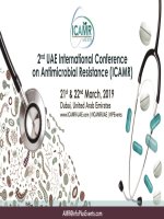
Figure #9 below compares the sun’s emission spectra against a Xenon arc emission pattern using
daylight filter combination
Figure #9 – Sunlight (outdoor) vs Xenon arc unit with daylight filter
(Source: From : Sunlight, Weathering & Light Stability Testing. Q-Lab, Technical Bulletin LU-0822)
COPYRIGHT © 2017 BY MICOM LABORATORIES |UV TESTING LABORATORY |1-888-996-4266 | WWW.MICOMLAB.COM
20
Xenon arc UV exposure is used across many industries. There are many standards and specifications requiring Xenon arc exposure as can be seen in Appendix 1.
Over the years Xenon arc and Fluorescent light units (discussed later on) have replaced carbon arc
as a light source for ultraviolet aging to a very large extent. Xenon arc units offer the following advantages over carbon arc units:
• Steadier emission pattern
• Simulates more closely sun’s own emission spectrum both in relative intensity and spectral distribution
• Allows to distinguish and simulate both direct sun exposure (outdoor conditions) and sun exposure
through glass (indoor conditions)
• Xenon is a relatively good time predictor thus allowing for more accurate accelerated aging
TIME COMPRESSION FACTOR
Experience demonstrates that the time compression factor concept (i.e. the rate of accelerated aging
induced by the exposure), is often poorly understood. How does test chamber exposure time compare to outdoor exposure time? What is the acceleration factor? How long do I have to test my product to simulate 5 years of outdoor exposure?
For decades, weathering experts have tried to find that magic number. The truth however is that there
is no such magic number. No matter how the question is formulated, the answer is always the same:
“It depends!”
It depends for one simple reason: Mother Nature is not as reliable as lab equipment and different materials will react differently. In some cases, even the same material available in different colors will react differently, depending of the color being used.
Xenon arc testing requires the use of calibrated lamps, specific filters, very accurately monitored irradiance, purified (demineralized) water, controlled atmosphere (humidity and temperature) and predefined light, dark and rain cycles durations. On the other hand, natural outdoor exposure depends on
when and where you are: Latitude, altitude, cloudiness, humidity, smog, rain, temperature, orientation, season, time of day, and many more. All those parameters have a major influence on the “efficiency” of outdoor exposure.
In other words, if you were to spend 5 minutes in a weathering chamber, no matter when or where
you do it, you would always get the same “tan”. On the other hand, we cannot say that 5 minutes of
COPYRIGHT © 2017 BY MICOM LABORATORIES |UV TESTING LABORATORY |1-888-996-4266 | WWW.MICOMLAB.COM
21
outdoor exposure in downtown London in December is equivalent to 5 minutes of outdoor exposure
in Miami in June. Presented this way, the answer is obviously ‘‘No’‘. That is exactly why it is impossible to have an ABSOLUTE acceleration factor for accelerated weathering testing.
SO, WHY IS XENON ARC UV AGING SO POPULAR AND USEFUL?
Xenon arc testing is actually a very powerful tool for comparative purposes. Testing simultaneously
multiple formulas can quickly give vital information. Instead of waiting years to get the data from outdoor exposure or feedback from customers, accelerated weathering gives you the data you need in
days or weeks.
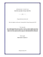
Photograph #3: 6500 Watts
Xenon arc as seen through a
safety lens
How fast is fast?
Even if the absolute acceleration factor cannot be determined for the reasons explained above, experience shows that using accelerated weathering, conclusions can usually be drawn after weeks
(sometimes days) while natural outdoor exposure takes months or years.
In a world where time is money and where technologies and trends are constantly moving, Xenon arc
testing has become a key asset for decision makers in many industries.
COPYRIGHT © 2017 BY MICOM LABORATORIES |UV TESTING LABORATORY |1-888-996-4266 | WWW.MICOMLAB.COM
22
PREVALENT PRACTICE
The most prevalent practice in North America for xenon arc UV testing is ASTM G155 - Practice for
Operating Xenon Arc Light Apparatus for Exposure of Non- Metallic Materials. This practice is the basis of all of the other standards for accelerated weathering using Xenon Arc UV light sources to simulate exposure to natural sunlight on an accelerated basis. Many standards call up this practice; for a
list by product category please review Appendix 1.
ASTM G155 is used to perform accelerated aging on a wide range of products and industries including products for the automotive industry, surface coatings, pharmaceutical light stability tests, printing inks, roofing, rubber, adhesives, textiles, geotextiles and many others.
When testing your products using this practice, the samples are exposed to repetitive cycles of light
and moisture under controlled environmental conditions. Moisture is usually produced by spraying
the test specimen with demineralized water or by the condensation of water vapor onto the specimen.
XENON ARC TESTING – EXPERIMENTAL PARAMETERS TO SPECIFY
To perform an accelerated weathering test that is relevant for your application the following test parameters need to be defined carefully:
• Lamp filters
• The choice of boro-silicate - Soda Lime filters is to be used should you wish to expose your
samples to indoor conditions. The choice of boro-silicate (inner and outer filters) will yield outdoor sun exposure conditions.
• The lamp irradiance level
• Irradiance is the light intensity you wish to use to expose your sample to UV light. It is normally
expressed in units of Watts/square-meter/nanometer. The light intensity is measured at 340 nm
for exterior conditions or at 420 nm for indoor exposure. The irradiance can also be measured
over a wavelength range e.g.: 300-400 nm.
• The type and duration of moisture exposure
• Water spray at the back of the front of the samples or only one of them. Usually spraying the
samples back will be for generating condensation at the specimen’s surface. Spraying the
sample’s front, or UV exposed part, will be for simulating surface erosion that allows to remove
surface residues that might be generated upon testing and that could act as a self-protecting
phenomena, example: chalking
• The timing of the light and moisture exposure
• The temperature of light exposure
COPYRIGHT © 2017 BY MICOM LABORATORIES |UV TESTING LABORATORY |1-888-996-4266 | WWW.MICOMLAB.COM
23
• Also know as “black panel temperature”. As discussed above, the sample’s surface temperature will control to a large extent the rate of the aging process. An instrumented metal panel
painted black is set on the samples rack and sends a signal to the control system to accurately
maintain the sample’s surface temperature
• The temperature of moisture exposure
• The light/dark cycle timing.
• We discussed above of the importance of having a “dark” cycle within the overall cycle to allow
for secondary reaction to take place.
There are twelve predefined cycles in table X3.1 of ASTM G-155 that can be used when doing xenon
arc testing. Other standards may also alter the cycle for specific purposes.
Photograph #4: sample set up in a Xenon arc unit
COPYRIGHT © 2017 BY MICOM LABORATORIES |UV TESTING LABORATORY |1-888-996-4266 | WWW.MICOMLAB.COM
24