Sổ tay module cân SIWAREX MS
Bạn đang xem bản rút gọn của tài liệu. Xem và tải ngay bản đầy đủ của tài liệu tại đây (1.22 MB, 75 trang )
SIWAREX
®
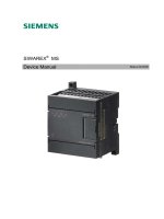
MS
Device Manual
Status 04/2006
Warning and Safety Terms
This manual contains notices that are for your personal safety and to prevent damage to
devices or surroundings. These notices are indicated by a warning triangle and are presented
as follows depending on the degree of danger:
!
Danger
means, that death, severe injury or considerable material damage may result, if
the respective safety measures are not taken.
!
Warning
Means that death, severe injury or serious material damage can result if the corresponding safety
precautions are not followed carefully.
!
Caution
Means that material damage or minor injuries can result if the corresponding safety precautions are
not followed carefully.
Caution
Means that material damage can result if the corresponding safety precautions
are not followed carefully.
Attention
Refers to important information on the product, handling of a product or a
corresponding segment of the documentation to which special attention should be
given.
Qualified Personnel
Commissioning and operation of a device may only be performed by qualified personnel. Qualified personnel as
indicated in the safety information in this manual are people that have the authorization to install, ground and label
devices, systems and power circuits.
Intended Utilization
!
Warning
The device may only be utilized for the applications described in the catalog and the technical
description and only in conjunction with external devices and components that are approved or
recommended by Siemens.
Fault-free and safe operation of the product depend on proper transport, proper storage, assembly,
installation, operation and maintenance.
Brand names / Trademarks
SIWAREX®, SIMATIC®, SIMATIC HMI® and SIMATIC NET® are trade marks of the Siemens
AG. The other designations in this info may be trade marks the use of which by third persons for
their own purposes might infringe proprietor rights.
Copyright
©
Siemens AG 2005 All rights reserved
Circulation or duplication of this document, utilization and
disclosure of its contents are not permitted unless explicitly
approved. Offenders will be liable for damages. All rights
reserved, including rights created by granting of patents or
registration of a utility model or design.
Siemens AG
Automation & Drives Dept.
SIWAREX Weighing Systems
A&D PI 14
Östliche Rheinbrückenstr. 50
D-76187 Karlsruhe
Disclaimer
We have tested the contents of this document for compatibility
with the hardware and software described. This does not
exclude the possibility of discrepancies, in which case we do
not guarantee the complete compatibility of this document. The
information in this document is assessed regularly and any
necessary corrections are included in the next revision.
We are grateful for any suggestions for improvement.
© Siemens AG 2005
Subject to change without notice.
iv SIWAREX MS
Safety Instructions
Table of Contents
Preface
1
Scope of Delivery
2
Product Overview
3
Hardware Configuration and
Assembly
4
Weighing Functions
5
Commands
6
Messages and Diagnosis
7
Programming in STEP 7
8
Setting the Scale – SIWATOOL MS
9
Accessories
10
Technical Data
11
Index
12
SIWAREX MS
Weigh module for SIMATIC S7-200
Device Manual
Abbreviations
13
Revision 1/2006
SIWAREX MS v
Contents
1 PREFACE 1-1
1.1 PURPOSE OF MANUAL 1-1
1.2 BASIC KNOWLEDGE REQUIRED 1-1
1.3 SCOPE OF MANUAL 1-1
1.4 FURTHER SUPPORT 1-2
2 SCOPE OF DELIVERY 2-3
2.1 SCOPE OF DELIVERY 2-3
2.2 RELEASED SIMATIC S7-200 CPUS 2-3
3 PRODUCT OVERVIEW 3-4
3.1 GENERAL 3-4
3.2 AREA OF APPLICATION 3-4
3.3 STRUCTURE 3-5
3.4 FUNCTION 3-6
3.5 SYSTEM INTEGRATION IN SIMATIC S7-200 3-6
3.6 SCALE ADJUSTMENT WITH SIWATOOL MS 3-6
4 HARDWARE CONFIGURATION AND ASSEMBLY 4-8
4.1 CONFIGURING THE HARDWARE 4-9
4.2 STRUCTURE TO EMC GUIDELINES 4-9
4.2.1 Definition: EMC 4-9
4.2.2 Introduction 4-9
4.2.3 Possible Effects of Interference 4-9
4.2.4 Coupling Mechanisms 4-10
4.2.5 Five Basic Rules for Guaranteeing EMC 4-10
4.3 ASSEMBLY 4-11
4.4 CONNECTION AND WIRING 4-12
4.4.1 Connection Areas for SIWAREX MS 4-12
4.4.2 Shielding Connection 4-12
4.4.3 Connection of 24 V Power Supply 4-13
4.4.4 Ground Connection to the Interference Dissipation 4-13
4.4.5 Load Cell Connection 4-13
4.4.6 Connecting the Remote Display from Siebert 4-16
4.4.7 Connecting the PC for SIWATOOL MS 4-16
4.4.8 LED Display Elements 4-17
4.5 PREPARING FOR OPERATION 4-18
5 WEIGHING FUNCTIONS 5-19
5.1 GENERAL 5-19
5.2 DS3 ADJUSTMENT PARAMETER 5-19
5.2.1 DS3 – Adjustment Digits 0, 1, 2, for Zero Point and Adjustment Weights 1, 2 5-21
5.2.2 DS3 – Characteristic Value Range 5-24
5.2.3 DS3 – Measurement Time 5-24
5.2.4 DS3 – Low Pass Filter 5-24
5.2.5 DS3 – Limit Frequency 5-25
5.2.6 DS3 – Depth of Average Value Filter 5-25
5.2.7 DS3 – Scale Name 5-25
5.2.8 DS3 – Minimum Weight for the Weighing Range 5-26
5.2.9 DS3 – Weighing Range 5-26
5.2.10 DS3 – Numeral Step 5-26
5.2.11 DS3 – Standstill Time 5-26
5.2.12 DS3 – Standstill Range 5-26
vi SIWAREX MS
5.2.13 DS3 – Decimal Place for Remote Display and ASCII Weight Output 5-27
5.2.14 DS3 – Maximum Negative Weight for Zero Setting 5-27
5.2.15 DS3 – Maximum Positive Weight for Zero Setting 5-27
5.2.16 DS3 – Tare Max. Weight T 5-27
5.2.17 DS3 – TTY Protocol Selection 5-27
5.2.18 DS3 – Reserve 5-27
5.2.19 DS3 – Unit of Measurement 5-27
5.3 DS 4 LIMIT VALUE PARAMETERS 5-28
5.3.1 DS 4 – Switch On Weight, Limit Value 1 5-28
5.3.2 DS 2 – Switch-off weight, Limit value 1 5-29
5.3.3 DS 4 – Switch-on weight, Limit value 2 5-29
5.3.4 DS 4 – Switch-off weight, Limit value 2 5-29
5.3.5 DS 4 – Basis Weight for Limit Values 5-29
5.4 DS 9 INFO ON MODULE 5-29
5.5 DS 15 TARE ENTRY 5-30
5.5.1 DS 15 – Tare Entry 5-30
5.6 DS 26 INTERNAL PROCESS VALUES 5-30
5.7 DS 30 PROCESS VALUES 5-31
5.7.1 DS 30 – Scale Status 5-32
5.7.2 DS 30 – Operating Errors 5-33
5.7.3 DS 30 – Gross Process Value 5-33
5.7.4 DS 30 – Net Process Value 5-33
5.7.5 DS 30 – Tare Process Value 5-33
5.7.6 DS 30 – G/N Weight 5-33
5.7.7 DS 30 – G/N Weight_x10 5-33
5.7.8 DS 30 – Tare 5-33
5.7.9 DS 30 – Unfiltered Raw Digit Value from AD Converter 5-33
5.7.10 DS 30 – Filtered Digital Value from the AD Converter 5-34
5.7.11 DS 30 – ASCII Weight Value 5-34
5.7.12 DS 30 – Runtime Duration 5-34
6 COMMANDS 6-35
6.1 COMMAND GROUPS 6-35
6.2 COMMAND LIST 6-35
7 MESSAGES AND DIAGNOSIS 7-37
7.1 MESSAGE TYPES 7-37
7.2 MESSAGE PATHS 7-37
7.3 DETECTION OF MESSAGES USING SIWATOOL MS 7-37
7.4 DETECTION OF MESSAGES USING THE MICROSCALE LIBRARY 7-38
7.5 MESSAGE LIST DATA AND OPERATING ERRORS (SYNCHRONOUS MESSAGES) 7-39
7.6 MESSAGE LIST OF OPERATING MESSAGES (ASYNCHRONOUS ERRORS) 7-40
7.7 MESSAGES VIA LEDS 7-42
8 PROGRAMMING IN STEP 7-MICRO/WIN 8-43
8.1 GENERAL 8-43
8.2 PRESETTING THE SYSTEM DATA MODULE 8-43
8.3 USING THE “MICROSCALE” LIBRARY IN MICRO/WIN 8-45
8.4 SIWAREX MS IN CYCLIC PROGRAM 8-47
8.5 CALL PARAMETER OF THE MICROSCALE LIBRARY 8-48
8.5.1 First_AEW, Second_AEW, Third_AEW, Fourth_AEW: IN, WORD 8-48
8.5.2 FirstVB_POINTER: IN, DWORD 8-48
8.5.3 Lib_Error_Bits: IN_OUT, WORD 8-48
8.5.4 First_AAW, Second_AAW, Third_AAW, Fourth_AAW: OUT, WORD 8-48
8.6 VARIABLE MEMORY ALLOCATION 8-49
SIWAREX MS vii
8.7 SIWAREX MS GETTING STARTED 8-50
8.7.1 STEP 7-Micro/Win Program 8-50
8.7.2 Operating and Monitoring for TP 177Micro Based on WinCC Flexible 8-50
9 SETTING THE SCALE – SIWATOOL MS 9-52
9.1 GENERAL 9-52
9.2 WINDOWS AND FUNCTIONS OF SIWATOOL MS 9-52
9.3 SETTING THE PARAMETER OFFLINE 9-52
9.4 SETTING THE PARAMETER ONLINE 9-52
9.5 HELP 9-53
10 ACCESSORIES 10-54
11 TECHNICAL DATA 11-57
11.1 INTEGRATION IN THE AUTOMATION SYSTEMS 11-57
11.2 24 V POWER SUPPLY 11-57
11.3 POWER SUPPLY FROM S7-200 BUSLINE 11-57
11.4 LOAD CELL CONNECTION 11-58
11.5 RS 232C INTERFACE 11-58
11.6 TTY INTERFACE 11-59
11.7 DIMENSIONS AND WEIGHT 11-59
11.8 ENVIRONMENTAL CONDITIONS 11-59
11.9 MECHANICAL REQUIREMENTS AND DATA 11-60
11.10 ELECTRICAL-, EMC- AND CLIMATIC REQUIREMENTS 11-60
11.10.1 Electrical Protection and Safety Requirements 11-60
11.10.2 Electromagnetic compatibility 11-62
11.10.3 Climatic Requirements 11-64
12 INDEX 12-65
13 ABBREVIATIONS 13-67
ILLUSTRATIONS
FIGURE 3-1 SIWAREX MS - SYSTEM OVERVIEW 3-5
FIGURE 3-2 SIWATOOL MS OVERVIEW 3-7
FIGURE 4-1 SIWAREX MS CONNECTION AREAS 4-12
FIGURE 4-2 SHIELDING CONNECTION FOR LOAD CELL CABLE 4-13
FIGURE 4-3 LOAD CELL CONNECTION WITH A 4-WIRE SYSTEM 4-15
FIGURE 4-4 LOAD CELL CONNECTION WITH A 6-WIRE SYSTEM 4-15
FIGURE 4-5 CONNECTING THE S102 DISPLAY 4-16
FIGURE 4-6 CONNECTING THE PC 4-16
FIGURE 5-1 ADJUSTMENT DIGITS AND WEIGHT VALUE 5-23
FIGURE 5-2 LINEARIZATION OF THE SCALE CHARACTERISTIC CURVE 5-24
FIGURE 5-3 STEP RESPONSE OF DIGITAL LOW PASS FILTER AT FG = 2 HZ 5-25
FIGURE 5-4 STANDSTILL MONITORING 5-26
FIGURE 5-5 PARAMETER DEFINITION OF LIMIT VALUES 5-29
FIGURE 8-1 SYSTEM DATA MODULE BEFORE THE ADJUSTMENT 8-43
FIGURE 8-2 SYSTEM DATA MODULE AFTER THE ADJUSTMENT (FOR 4 SIWAREX MS
MODULE)
8-44
FIGURE 8-3 MODULE ADRESS 8-44
FIGURE 8-4 LINKING THE LIBRARY INTO MICRO/WIN 8-45
FIGURE 8-5 MICROSCALE LIBRARY BOUND INTO MICRO/WIN 8-46
FIGURE 8-6 CALL PARAMETER OF THE LIBRARY MICROSCALE FOR A SCALE 8-47
FIGURE 8-7 CALL PARAMETER OF THE LIBRARY MICROSCALE FOR TWO SCALES 8-
47
FIGURE 8-8 PROGRAM CALLS IN PROJECT SIWAREX MS GETTING STARTED 8-50
viii SIWAREX MS
FIGURE 8-9 OVERVIEW SCREEN FOR SIWAREX MS IN TP077MICRO 8-51
FIGURE 9-1 SIWATOOL MS WINDOWS 9-53
Tables
TABLE 1-1 SCOPE OF THIS MANUAL 1-1
TABLE 1-2 OVERVIEW OF THE CHAPTER 1-2
TABLE 4-1 EXPANSION MODULE IN THE S7-200 SYSTEM 4-9
TABLE 4-2 LOAD CELL CONNECTIONS 4-14
TABLE 4-3 DISPLAY ELEMENTS (LED) 4-17
TABLE 5-1 ALLOCATION OF DS3 5-21
TABLE 5-2 ALLOCATION OF DS 4 5-28
TABLE 5-3 ALLOCATION OF DS 9 5-30
TABLE 5-4 ALLOCATION OF DS 15 5-30
TABLE 5-5 ALLOCATION OF DS 26 5-31
TABLE 5-6 ALLOCATION OF DS 30 5-31
TABLE 5-7 STATUS INFORMATION 5-32
TABLE 5-8 OPERATING ERROR (BIT INFORMATION) 5-33
TABLE 6-1 SIWAREX MS COMMAND LIST 6-36
TABLE 7-1 LIST OF DATA AND OPERATING ERRORS 7-40
TABLE 7-2 LIST OF OPERATING MESSAGES 7-41
TABLE 7-3 MESSAGE BYTE FOR OPERATING MESSAGES 7-41
TABLE 7-4 LIST OF LED MESSAGES 7-42
TABLE 8-1 VARIABLE MEMORY ALLOCATION 8-49
TABLE 10-1 ACCESSORIES 10-56
TABLE 11-1 SIMATIC CPU 11-57
TABLE 11-2 DATA: 24 V POWER SUPPLY 11-57
TABLE 11-3 DATA: POWER SUPPLY FROM THE SIMATIC BUS 11-57
TABLE 11-4 DATA: LOAD CELL CONNECTION 11-58
TABLE 11-5 DATA: RS 232C INTERFACE 11-58
TABLE 11-6 DATA: TTY INTERFACE 11-59
TABLE 11-7 DATA: DIMENSIONS AND WEIGHT 11-59
TABLE 11-8 DATA: ENVIRONMENTAL CONDITIONS 11-59
TABLE 11-9 DATA: MECHANICAL REQUIREMENTS 11-60
TABLE 11-10 DATA: ELECTR. PROTECTION AND SAFETY REQUIREMENTS 11-62
TABLE 11-11 DATA: ELECTROMAGNETIC COMPATIBILITY 11-63
TABLE 11-12 DATA: CLIMATIC REQUIREMENTS 11-64
SIWAREX MS ix
Preface
1 Preface
1.1 Purpose of Manual
This manual contains all the information required to set up and operate the
SIWAREX MS.
1.2 Basic Knowledge Required
To understand this manual, a general knowledge of SIMATIC S7-200 automation
technology is required. Weighing technology is also beneficial.
1.3 Scope of Manual
This manual applies to the SIWAREX MS - Expansion module:
Type
Name Order number From product
revision (Version)
SIWAREX MS SIWAREX
Micro Scale
7MH4930-0AA01 HW 1 FW
V. 1.0
Table 1-1 Scope of this manual
Note
This manual describes the SIWAREX MS weighing electronics as part of the
SIMATIC S7-200 system and should be used as a supplement to the manual for
the S7-200.
Note
This manual contains a description of the module that is valid at the time of
publication.
We reserve the right to supply new modules or newer versions of modules with
product information containing current information about the module.
SIWAREX MS 1-1
Preface
The layout of this manual is based on activities that must be performed as part of
configuration, commissioning, operation and service / maintenance.
Chapter
Description of Content
1 Preface
Notes on using this manual
2 Scope of Delivery
Description of the SIWAREX MS delivery
contents.
3 Product Overview
Overview of
- Structure
- Functionality
- System integration
of SIWAREX MS.
4 Hardware
Configuration and
Assembly
Description
- of individual hardware components
- of structure and installation
- of connections
- of preparations for operation.
5 Weighing Functions
Description of all weighing parameters and
corresponding functions.
6 Commands
Description of commands that can be executed
by SIWAREX MS.
7 Messages and
Diagnosis
Description of messages with notes on
problem resolution.
8 Programming in STEP
7
Description of data exchange with the
SIMATIC CPU. This chapter is meant for you if
you write application software.
9 Setting the Scale –
SIWATOOL MS
Description of software functions
10 Accessories
Ordering information for optional components
such as:
- Remote digital displays
- Ex-Interface
- Connection cables
11 Technical Data
Technical Data
12 Index
Index
13 Abbreviations
List of Abbreviations
Table 1-2 Overview of the chapter
1.4 Further Support
Do you still have questions concerning the use of the SIWAREX MS? Then please
contact your Siemens representative in the office or business location that is
responsible for your area or technical support for SIWAREX
Tel.: +49 (0)721 595 2811.
Updated information concerning SIWAREX weighing technology can be found on
the Internet site.
1-2 SIWAREX MS
Scope of Delivery
2 Scope of Delivery
2.1 Scope of Delivery
The declaration of conformity from the manufacturer and an additional sheet
containing up-to-date product information are included in the scope of delivery of
the SIWAREX MS.
To configure the SIWAREX MS, you will require the SIWAREX MS configuration
package, which must be ordered separately.
The configuration package consists of the following components:
- The SIWATOOL MS Windows program for setting up the scale during
commissioning
- Standard software for operating the SIWAREX MS in SIMATIC S7-200
- Device manuals in several languages
The “Getting Started” software is extremely useful during the first steps of
programming. It is located on the supplied CD along with the configuration package
or it can be obtained free of charge on the Internet (
www.siwarex.com).
Any necessary or optional accessories are detailed in chapter
10 Accessories.
2.2 Released SIMATIC S7-200 CPUs
SIWAREX MS can be operated with the following S7-200 CPUs:
6ES7212-1AB23-0XB0, 6ES7212-1BB23-0XB0, 6ES7214-1AD23-0XB0,
6ES7214-1BD23-0XB0, 6ES7214-2AD23-0XB0, 6ES7214-2BD23-0XB0,
6ES7216-2AD23-0XB0, 6ES7216-2BD23-0XB0.
SIWAREX MS can also be used with the S7-200 SIPLUS CPUs but SIWAREX MS
itself is not designed for expanded environmental conditions:
6AG1212-1AB23-2XB0, 6AG1212-1BB23-2XB0, 6AG1214-1AD23-2XB0,
6AG1214-1BD23-2XB0, 6AG1214-2AD23-2XB0, 6AG1214-2BD23-2XB0,
6AG1216-2AD23-2XB0, 6AG1216-2BD23-2XB0.
SIWAREX MS 2-3
Product Overview
3 Product Overview
3.1 General
SIWAREX MS (Micro Scale) is a versatile and flexible weighing module, which can
be used wherever scales are to be used in the SIMATIC S7-200 automation
system or a force measurement is necessary.
The SIWAREX MS module advantageously utilized all features of the modern
automation system, such as integrated communication, the diagnostics system and
the available configuration tools.
Customer benefits:
SIWAREX MS is characterized by a few clear advantages:
o Standardized connection technology and integrated communication due to use
in SIMATIC S7-200
o Standardized configuration with STEP 7 Micro/Win Version 4.0 SP2 and higher
o Weight or force measurement to a high resolution of 16 Bit
o Height accuracy 0.05 %
o Fast measuring times can be chosen between 20 ms or 33 ms
o Monitoring of limit values
o Flexible adaptation to different requirements with SIMATIC control
o Easy adjustment of scales using the SIWATOOL MS program via the RS 232
interface
o Theoretical adjustment without adjustment weights
o Exchange of module, possibly without readjusting scales
o Intrinsically safe load cell power for use in zone 1 areas with risk of explosion
(Option SIWAREX IS)
o Diagnostics functions
3.2 Area of Application
SIWAREX MS is the optimum solution wherever signals from STRAIN GAUGE
sensors or load cells are to be recorded. SIWAREX MS provides high accuracy as
weighing electronics. With measuring times of 20 ms (or 33 ms), the module can
also be used for electronic evaluation for force measurement.
SIWAREX MS is optimally equipped for the following applications:
Non-Automatic Weighing Instrument
Discontinuous and continuous weighing processes
Filling level monitoring for Silos and Bunkers
3-4 SIWAREX MS
Product Overview
Measurement of Crane and Cable loads
Load measurement with industrial lifts or rolling mills
Scales in explosion hazard areas (Zone 2 or Zone 1 with Ex-Interface SIWAREX IS or Pi)
Monitoring belt tension
Force measurement, container scales, platform scales and crane scales
3.3 Structure
SIWAREX MS is an expansion module for the SIMATIC S7-200 and operates
together with other expansion modules of the system. The installation and cabling
for the 71,2 mm wide module is minimal. Load cell, power supply and TTY
interface connections are made with screw terminals and the RS232 serial
interface with a 9-pin D-sub connector. Weighing electronics can be completely
integrated into the automation system with SIWAREX MS operation in SIMATIC.
Figure 3-1 SIWAREX MS - System overview
SIWAREX MS 3-5
Product Overview
3.4 Function
The primary task of the SIWAREX MS consists of measuring the actual weight
value. Integration into SIMATIC enables the processing of weight values directly in
the PLC.
SIWAREX MS is already being adjusted in house. This means that the scale can
be adjusted to theoretical settings without using any adjustment weights and
modules can be exchanged without readjusting the scale.
The SIWAREX MS has two serial interfaces. A TTY interface is used for
connecting remote digital displays. A PC can be connected to the RS 232 interface
to set up the scale using the SIWATOOL MS.
The SIWAREX MS weighing module can be used in zone 2 explosion hazard
areas. An optional Ex interface on SIWAREX IS or SIWAREX Pi gives load cells an
intrinsically safe power supply for applications in zone 1.
3.5 System Integration in SIMATIC S7-200
SIWAREX MS is a component of SIMATIC S7-200. This gives you complete
freedom for configuration of the automation solution - including the weighing
application. The optimum solution can be created for small, medium and large
systems by selectively combining the SIMATIC components. Customer specific or
branch specific solutions can be developed quickly and easily using the
configuration package and the “ready to use” application “Getting started”.
3.6 Scale Adjustment with SIWATOOL MS
For adjustment of the scale, there is a special program - SIWATOOL MS for
Windows operating systems (Windows XP and higher).
The program allows the weighing specialist to commission the scale without having
to understand automation technology. During servicing, you can analyze the
processes in the scale and test them with the aid of a PC independently of the
automation system. Reading the diagnostic buffer from the SIWAREX MS is very
helpful in analyzing events.
3-6 SIWAREX MS
Product Overview
The following figure shows the structure of the individual program windows.
Figure 3-2 SIWATOOL MS Overview
SIWATOOL MS does more than support you in adjusting the scale. It is very useful
to analyze the diagnostic buffer, the contents of which can be saved along with the
parameters after reading from the module.
You can switch between languages German, English, French, Italian and Spanish
in the program.
SIWAREX MS 3-7
Hardware Configuration and Assembly
4 Hardware Configuration and Assembly
!
Warning Notes
For configuration, assembly and commissioning, the definitions from the manual for
the SIMATIC S7-200 are applicable. This chapter provides you with additional
information for hardware configuration and assembly, and for preparing the
SIWAREX MS for operation.
The technical safety information is to be strictly adhered to.
!
Warning
Unqualified intervention in the device/system or not adhering to the warning notices
can result in serious injury or damage to equipment. Only qualified personnel are
permitted to access the operational components of this device / system.
!
Warning
The unit has been developed, manufactured, tested and documented in
accordance with the corresponding safety standards. The device itself will not
cause any danger to equipment or personal health under normal circumstances.
!
Danger
Commissioning is not permitted until it is guaranteed that the machine in which
these components are to be integrated conforms with the guidelines in
89/392/EWG (within the European Union).
4-8 SIWAREX MS
Hardware Configuration and Assembly
4.1 Configuring the Hardware
SIWAREX MS is an analog expansion module running in the SIMATIC S7-200
automation system.
The maximum possible number of SIWAREX MS expansion modules per rack
corresponds with the maximum number of expansion modules of the respective
CPU type according to the S7-200 system manual.
CPU type Max number of
SIWAREX MS
CPU 222 2
CPU 224 4
CPU 226 7
Table 4-1 Expansion module in the S7-200 system
The utilization of other expansion modules can reduce the permitted number of
SIWAREX MS. Check the current requirements on the expansion bus according to
the S7-200 system manual.
Selecting the suitable SIMATIC CPU, the SIMATIC HMI (Human Machine
Interface) does not only depend on weighing technology requirements but also on
the overall job that the automation system has to perform.
4.2 Structure to EMC Guidelines
SIWAREX MS is a highly precise measuring device, which must measure low
signal levels (approx. 1.5 µV) reliably. Because of this, proper assembly and wiring
are absolutely essential for fault-free operation.
4.2.1 Definition: EMC
EMC (Electromagnetic Compatibility) describes the ability of an electrical device to
function without faults in a defined electromagnetic environment without being
influenced by its surroundings and without negatively influencing the surroundings.
4.2.2 Introduction
Although SIWAREX MS was developed for use in industrial environments and
meets high EMC specifications, you should carry out EMC planning before
installing your controller to determine and take into account any possible
interference sources.
4.2.3 Possible Effects of Interference
Electromagnetic interference can influence the automation system and the
SIWAREX MS in various ways:
- Electromagnetic fields that have a direct influence on the system
- Interference through process cabling (e.g. measurement lines)
SIWAREX MS 4-9
Hardware Configuration and Assembly
- Interference infiltrating the system through the power supply and/or protective
ground
Interference can impair the fault-free functioning of the SIWAREX MS.
4.2.4 Coupling Mechanisms
Depending on the means of distribution (conductive or non-conductive bound) and
the distance between the interference source and the device, interference can be
introduced into the automation system through four different coupling mechanisms.
Galvanic coupling
Capacitive coupling
Inductive coupling
Radiation coupling
4.2.5 Five Basic Rules for Guaranteeing EMC
If you follow these five basic rules, EMC can be guaranteed in most cases!
Rule 1: Large surface area grounding connection
Ensure that while installing the automation devices, a well-made large surface area
ground connection is made between the inactive metal components (see following
sections).
Connect all inactive metal components and low-impedance components with
ground (broad cross-section).
Use screwed connections on painted or anodized metal surfaces either with
special contact washers or remove the insulated protective surface at the contact
points.
Do not use aluminum components for ground connections if at all possible.
Aluminum oxidizes easily and is therefore less suitable for grounding connections.
Find a central location for connections between the grounding point and the ground
wiring system.
Rule 2: Proper wiring
Separate the cabling into groups (high-voltage lines, power supply lines, signal
lines, ground wiring, data lines etc.).
Run the high-voltage lines and ground wiring or data cables in separate channels
or bundles.
Run measurement lines as close to grounding surfaces as possible (e.g. support
beams, metal rails, cabinet panels).
4-10 SIWAREX MS
Hardware Configuration and Assembly
Rule 3: Fixed cable shielding
Ensure that the cable shielding is connected properly.
Use shielded data lines only. The shielding must be connected to ground using a
large surface area at both ends of the data lines.
The shielding of measurement lines must also be connected to ground at both
ends.
The shielding should continue right up to the connection area. Unshielded cable
ends should be kept as short as possible. Connect the cable shielding directly next
to the SIMATIC on the shielding connection clamp. The connection between the
shielding rail and the cabinet/housing must be low impedance.
Use metallic or metal-plated connector housings for the shielded data lines.
Rule 4: Special EMC measures
All inductivity that is to be controlled should be connected with suppressors.
Use interference suppressed fluorescent lighting or incandescent lamps for
illuminating cabinets or housings in the immediate vicinity of your controller.
Rule 5: Uniform reference potential
Create a uniform reference potential and ground all electrical operational elements.
Run sufficiently dimensioned potential equalizing cabling if potential differences
exist or are to be expected in the system. The respective potential compensation is
mandatory for Ex applications.
4.3 Assembly
When assembling the SIMATIC components and the SIWAREX MS, the
installation, assembly and wiring guidelines for the SIMATIC S7-200 must be
followed (see S7-200 manual).
This manual describes supplementary aspects of assembly and wiring that are
specific to the SIWAREX MS.
SIWAREX MS 4-11
Hardware Configuration and Assembly
4.4 Connection and Wiring
4.4.1 Connection Areas for SIWAREX MS
All connections can be made from the front.
Figure 4-1 SIWAREX MS connection areas
4.4.2 Shielding Connection
Special attention must be given to the shield strip for the shielded lines. Only
correct installation guarantees that the system will be immune to interference. A
cable is shielded to decrease the affects of magnetic, electrical and
electromagnetic interference on this line. Interference on cable shielding is routed
to ground through the shielding connection clamp. To ensure that this interference
does not become a source of interference, a low impedance connection to ground
is especially important.
Only use wires with braided shielding (see recommended cable types in chapter
10 Accessories). Shielding should provide at least 80% coverage.
The shielding clamps must be ordered separately. The following image shows the
shield clamp assembly.
4-12 SIWAREX MS
Hardware Configuration and Assembly
Figure 4-2 Shielding connection for load cell cable
4.4.3 Connection of 24 V Power Supply
The power supply 24 V is connected directly to the terminals M and L+ on the
SIWAREX MS expansion module.
4.4.4 Ground Connection to the Interference Dissipation
The ground wire is connected to a suitable point for dissipating interference.
4.4.5 Load Cell Connection
Measuring sensors can be connected to the SIWAREX MS if they are fitted with
strain gauges (full bridge) and meet the following conditions (see the technical data
as well – Chapter
11.4):
- Characteristic value 1 4 mV/V
- Supply voltage of 6 V is permissible
The following rules are to be followed when connecting load cells (WZ).
1. Use of a junction box (SIWAREX JB) is necessary if more than one load cell is
connected (the load cells must be connected in parallel). If the distance from a load
cell to SIWAREX MS or to the junction box is greater than the available length of
the load cell connecting cable, the SIWAREX EB extension box should be used.
2. The cable shielding is always run to the cable gland on the junction box
(SIWAREX JB) or the extension box.
If there is a danger of potential equalization currents on the cable shielding, a
potential equalization conductor should be run in parallel to the load cell cable.
SIWAREX MS 4-13
Hardware Configuration and Assembly
3. Twisted pair cables should be used for the specified lines and should also be
shielded:
- Sensor line SEN+ and SEN-
- Measuring voltage lines SIG+ and SIG-
- Supply voltage lines EXT+ and EXT-
We recommend using the cable indicated in chapter
10 Accessories.
4. The shielding must be connected to the shielding connection clamp.
The maximum distance between the SIWAREX MS and the load cell is applicable
when using the recommended cables.
The power supply (6V) for the load cells comes from the SIWAREX MS. (terminal
EXC+ and EXC-).
The connection should be made using the cable indicated in chapter
10 Accessories.
Connection and signal designations Comment
SEN+ Sensor line +
SEN- Sensor line -
SIG+ Measurement line +
SIG- Measurement line -
EXC+ Load cell supply output +
EXC- Load cell supply output -
Table 4-2 Load cell connections
4-14 SIWAREX MS
Hardware Configuration and Assembly
The two figures below show the load cell connection using 4-wire and 6-wire
systems.
Figure 4-3 Load cell connection with a 4-wire system
Figure 4-4 Load cell connection with a 6-wire system
SIWAREX MS 4-15
Hardware Configuration and Assembly
The maximum distance of 500 m applies to using cables as specified in chapter
10 Accessories.
4.4.6 Connecting the Remote Display from Siebert
The type S102 display made by Siebert can be connected to the TTY interface.
Figure 4-5 Connecting the S102 display
4.4.7 Connecting the PC for SIWATOOL MS
Ready-made cables are available for connecting to the PC (see
Accessories)
Figure 4-6 Connecting the PC
4-16 SIWAREX MS
Hardware Configuration and Assembly
4.4.8 LED Display Elements
Label
LED
color
LED Description
SF Red LED 1
System Fault
Hardware fault
Green LED 2
RUN
NET Green LED 3
Net
Green LED 4
Standstill
Orange LED 5
Write protection activated
→ 0 ←
Green LED 6
¼ d zero
MAX
Red LED 7
Max. exceeded
+ 24 VDC Green LED 8
24 V connected
P
Table 4-3 Display elements (LED)
For more information on LEDs, see chapter
7.7.
SIWAREX MS 4-17