Sổ tay module truyền thông CP 243-2 AS-Interface Master
Bạn đang xem bản rút gọn của tài liệu. Xem và tải ngay bản đầy đủ của tài liệu tại đây (769.05 KB, 142 trang )
Preface, Contents
Technical Description and
Installation Instructions
1
Interface to the User Program in
the S7-200
2
CP 242-8 as AS-Interface Master
3
Interface to PROFIBUS DP
(CP 242-8 as DP Slave)
4
Dealing with Problems /
Error Displays
5
Appendix
AS-Interface Protocol Implemen-
tation Conformance Statements
A
Structure of the PROFIBUS
Parameter Assignment and
Configuration Frame
B
References
C
Note on the CE Label
D
Glossary, Index
Release 01
C79000-G8976-C109
CP 242-8
AS-Interface Master /
PROFIBUS-DP Slave
Manual
SIMATIC NET
Industrial
Ethernet
PROFIBUS
AS–Interface
AS–Interface
Safety Guidelines
This
manual contains notices which you should observe to ensure your own personal safety
, as well as to protect
the product and connected equipment. These notices are highlighted in the manual by a warning triangle and are
marked as follows according to the level of danger:
!
Danger
indicates that death, severe personal injury or substantial property damage will result if
proper precautions are not taken.
!
Warning
indicates that death, severe personal injury or substantial property damage can, result if
proper precautions are not taken.
!
Caution
indicates that minor personal injury or property damage can result if proper precautions
are not taken.
Note
draws your attention to particularly important information on the product, handling the
product, or to a particular part of the documentation.
Qualified Personnel
Only
qualified personnel
should be allowed to install and work on this equipment. Qualified persons are defined
as persons who are authorized to commission, to ground, and to tag circuits, equipment, and systems in accor
-
dance with established safety practices and standards.
Correct Usage
Note
the following:
!
Warning
This device and its components may only be used for the applications described in the
catalog or the technical description, and only in connection with devices or components
from other manufacturers which have been approved or recommended by Siemens.
This product can only function correctly and safely if it is transported, stored, set up, and
installed correctly, and operated and maintained as recommended.
Trademarks
SIMATICR
and SIMA
TIC NET
R
are registered trademarks of SIEMENS AG.
Third parties using for their own purposes any other names in this document which refer to trademarks might in
-
fringe upon the rights of the trademark owners.
We have checked the
contents of this manual for agreement with the hard
-
ware
and software
described. Since deviations cannot be precluded entirely
,
we cannot guarantee full agreement. However, the data in this manual are
reviewed regularly and any necessary corrections included in subsequent
editions. Suggestions for improvement are welcomed.
Disclaimer of LiabilityCopyright Siemens AG 1997 All rights reserved
The reproduction,
transmission or use of this document or its contents is not
permitted without express written authority. Offenders will be liable for
damages.
All rights, including rights created by patent grant or registration of
a utility model or design, are reserved.
Siemens AG
Automation Group
Industrial Automation Systems
Postfach 4848, D-90327 Nuremberg
E Siemens AG 1997
Subject to change.
Siemens Aktiengesellschaft Order No. C79000-G8976-C109
iii
CP 242-8
AS-Interface Master / PROFIBUS DP Slave – Release 01
C79000–G8976–C109/01
Preface
Purpose
of the Manual
This manual supports you when using the CP 242-8 module. It explains how an
S7-200 CPU can address AS-i actuators and AS-i sensors via this module. The
manual also explains how to access an S7-200 station as a PROFIBUS DP slave
via the CP 242-8.
W
e recommend the following procedure when
you want an overall picture of the AS-Interface:
– First read the ‘AS-Interface Introduction and Basic Information’ manual (part
of this documentation package). This contains general information about the
AS-Interface abbreviated to AS-i in the following chapters.
You want to set up an AS-i system and include the CP 242-8 module in it:
– You will find the information you require about connecting and operating the
CP 242-8 module in Chapter 3.
You want to know how to operate the CP 242-8 from the point of view of the
PROFIBUS DP master:
– Read Chapter 4 in this manual.
Requirements
To understand this manual, you require the following:
S A working knowledge of PROFIBUS DP
S You should be familiar with the ‘AS-Interface Introduction and Basic Information’
manual (supplied with this documentation package).
Diskette
with Sample Program and T
ype/GSD File
The diskette accompanying this manual (S7-200 PROGR) contains sample
programs that will support and help you when programming the CP 242-8. These
sample programs were written with STEP 7 Micro/WIN and can be run on an
S7-200 CPU.
The diskette also contains the type and DDB file you require for configuring the CP
242-8 with your DP master.(See Section 4.4, Configuring the CP 242-8 on the DP
Master / Content of the Type File and the DDB file.)
iv
CP
242-8
AS-Interface Master / PROFIBUS DP Slave – Release 01
C79000–G8976–C109/01
Further
Support – Who to Contact
If you have technical questions about using the product described here, please
contact your local Siemens representative.
The addresses are listed:
S in our catalog IK 10
S on the Internet ()
Common Questions
Our customer support on the Internet provides useful information and answers to
frequently asked questions (FAQ). Under FAQ, you will find information about our
entire range of products.
The address of the AUT homepage in the World Wide Web of the Internet is as
follows:
/>Further Support – Hotline
S Our hotline is also available to deal with problems:
S Telephone: 0911 – 895 – 7000
(from abroad +49 – 911 – 895 – 7000)
S Telefax: 0911 – 895 – 7001
(from abroad +49 – 911 – 895 – 7001)
S E-Mail:
S Mailbox (BBS, analog/ISDN, 8N1):
0911 – 895 – 7100
(from abroad +49 – 911 – 895 – 7100)
-
v
CP 242-8
AS-Interface Master / PROFIBUS DP Slave – Release 01
C79000–G8976–C109/01
Contents
1 Technical Description and Installation Instructions 1-1.
. . . . . . . . . . . . . . . . . . . . . .
1.1 General 1-2
. . . . . . . . . . . . . . . . . . . . . . . . . . . . . . . . . . . . . . . . . . . . . . . . . . . . . . . .
1.2 Application of the Module 1-4.
. . . . . . . . . . . . . . . . . . . . . . . . . . . . . . . . . . . . . . . .
1.3 Technical Specifications of the Module 1-6.
. . . . . . . . . . . . . . . . . . . . . . . . . . . .
1.4 Installing the Module 1-7.
. . . . . . . . . . . . . . . . . . . . . . . . . . . . . . . . . . . . . . . . . . . .
1.5 Front Panel – Access to all Functions 1-8.
. . . . . . . . . . . . . . . . . . . . . . . . . . . . .
1.6 Connection Elements 1-9.
. . . . . . . . . . . . . . . . . . . . . . . . . . . . . . . . . . . . . . . . . . .
1.7 Display and Control Elements 1-11.
. . . . . . . . . . . . . . . . . . . . . . . . . . . . . . . . . . . .
1.7.1 Status Display 1-12.
. . . . . . . . . . . . . . . . . . . . . . . . . . . . . . . . . . . . . . . . . . . . . . . . .
1.7.2 Slave Display for AS-i Slaves 1-14.
. . . . . . . . . . . . . . . . . . . . . . . . . . . . . . . . . . . .
1.7.3 Displaying and Setting the PROFIBUS Address 1-16.
. . . . . . . . . . . . . . . . . . . .
1.8 Configuring the AS-Interface with the SET Button 1-18.
. . . . . . . . . . . . . . . . . .
2 Interface to the User Program in the S7-200 CPU 2-1.
. . . . . . . . . . . . . . . . . . . . . . . . .
2.1 CP 242-8 Connects the S7-200 CPU with PROFIBUS DP
and AS-Interface 2-2.
. . . . . . . . . . . . . . . . . . . . . . . . . . . . . . . . . . . . . . . . . . . . . . .
2.2 Addressing the CP 242-8 in the S7-200 CPU 2-4.
. . . . . . . . . . . . . . . . . . . . . .
2.3 Meaning of the Data in the Digital Module 2-7.
. . . . . . . . . . . . . . . . . . . . . . . . .
2.3.1 Identification Register in the Digital Module 2-8.
. . . . . . . . . . . . . . . . . . . . . . . .
2.3.2 Error Register in the Digital Module 2-9.
. . . . . . . . . . . . . . . . . . . . . . . . . . . . . . .
2.3.3 Status Byte (Input Register 8DI) 2-11.
. . . . . . . . . . . . . . . . . . . . . . . . . . . . . . . . . .
2.3.4 Control Byte (Output Register 8DO) 2-13.
. . . . . . . . . . . . . . . . . . . . . . . . . . . . . .
2.4 Meaning of the Data in the Analog Module 2-14.
. . . . . . . . . . . . . . . . . . . . . . . . .
2.4.1 Identification Register in the Analog Module 2-15.
. . . . . . . . . . . . . . . . . . . . . . .
2.4.2 Error Register in the Analog Module 2-16.
. . . . . . . . . . . . . . . . . . . . . . . . . . . . . .
2.5 Access to the Analog Input and Output Words 2-17.
. . . . . . . . . . . . . . . . . . . . .
2.5.1 Analog Input Area 2-18.
. . . . . . . . . . . . . . . . . . . . . . . . . . . . . . . . . . . . . . . . . . . . . .
2.5.2 Analog Output Area 2-20.
. . . . . . . . . . . . . . . . . . . . . . . . . . . . . . . . . . . . . . . . . . . .
3 CP 242-8 as AS-Interface Master 3-1.
. . . . . . . . . . . . . . . . . . . . . . . . . . . . . . . . . . . . . . . .
3.1 About this Chapter 3-2.
. . . . . . . . . . . . . . . . . . . . . . . . . . . . . . . . . . . . . . . . . . . . .
3.2 Addressing the AS-i Slaves with the User Program 3-3.
. . . . . . . . . . . . . . . . .
3.3 Access to the AS-i User Data 3-6.
. . . . . . . . . . . . . . . . . . . . . . . . . . . . . . . . . . . .
3.4 Signaling Errors and Diagnostic Information 3-7.
. . . . . . . . . . . . . . . . . . . . . . .
3.5 Command interface of the CP 242-8 3-9.
. . . . . . . . . . . . . . . . . . . . . . . . . . . . . .
3.6 Description of the AS-i Commands 3-13.
. . . . . . . . . . . . . . . . . . . . . . . . . . . . . . .
3.6.1 Set_Permanent_Parameter 3-18
. . . . . . . . . . . . . . . . . . . . . . . . . . . . . . . . . . . . . . .
vi
CP 242-8
AS-Interface Master / PROFIBUS DP Slave – Release 01
C79000–G8976–C109/01
3.6.2 Get_Permanent_Parameter 3-19
. . . . . . . . . . . . . . . . . . . . . . . . . . . . . . . . . . . . . .
3.6.3 Write_Parameter 3-20
. . . . . . . . . . . . . . . . . . . . . . . . . . . . . . . . . . . . . . . . . . . . . . . .
3.6.4 Read_Parameter 3-21
. . . . . . . . . . . . . . . . . . . . . . . . . . . . . . . . . . . . . . . . . . . . . . . .
3.6.5 Store_Actual_Parameters 3-22
. . . . . . . . . . . . . . . . . . . . . . . . . . . . . . . . . . . . . . . .
3.6.6 Set_Permanent_Configuration 3-23
. . . . . . . . . . . . . . . . . . . . . . . . . . . . . . . . . . . .
3.6.7 Get_Permanent_Configuration 3-24
. . . . . . . . . . . . . . . . . . . . . . . . . . . . . . . . . . . .
3.6.8 Store_Actual_Configuration 3-25
. . . . . . . . . . . . . . . . . . . . . . . . . . . . . . . . . . . . . . .
3.6.9 Read_Actual_Configuration 3-26
. . . . . . . . . . . . . . . . . . . . . . . . . . . . . . . . . . . . . . .
3.6.10 Set_LPS 3-27
. . . . . . . . . . . . . . . . . . . . . . . . . . . . . . . . . . . . . . . . . . . . . . . . . . . . . . .
3.6.11 Set_Offline_Mode 3-28
. . . . . . . . . . . . . . . . . . . . . . . . . . . . . . . . . . . . . . . . . . . . . . .
3.6.12 Select Autoprogramming 3-29.
. . . . . . . . . . . . . . . . . . . . . . . . . . . . . . . . . . . . . . . .
3.6.13 Set_Operation_Mode 3-30
. . . . . . . . . . . . . . . . . . . . . . . . . . . . . . . . . . . . . . . . . . . .
3.6.14 Change_Slave_Address 3-31
. . . . . . . . . . . . . . . . . . . . . . . . . . . . . . . . . . . . . . . . .
3.6.15 Read Slave Status 3-32.
. . . . . . . . . . . . . . . . . . . . . . . . . . . . . . . . . . . . . . . . . . . . .
3.6.16 Read Lists and Flags
(Get_LPS, Get_LAS, Get_LDS, Get_Flags) 3-33.
. . . . . . . . . . . . . . . . . . . . . . . .
3.6.17 Read Total Configuration 3-35.
. . . . . . . . . . . . . . . . . . . . . . . . . . . . . . . . . . . . . . . .
3.6.18 Configure Total System 3-37.
. . . . . . . . . . . . . . . . . . . . . . . . . . . . . . . . . . . . . . . . .
3.6.19 Write Parameter List 3-40.
. . . . . . . . . . . . . . . . . . . . . . . . . . . . . . . . . . . . . . . . . . . .
3.6.20 Read Parameter Echo List 3-41.
. . . . . . . . . . . . . . . . . . . . . . . . . . . . . . . . . . . . . .
3.6.21 Read Version ID 3-42.
. . . . . . . . . . . . . . . . . . . . . . . . . . . . . . . . . . . . . . . . . . . . . . .
3.6.22 Read and Delete Slave Status 3-43.
. . . . . . . . . . . . . . . . . . . . . . . . . . . . . . . . . . .
3.6.23 Read Slave ID 3-44.
. . . . . . . . . . . . . . . . . . . . . . . . . . . . . . . . . . . . . . . . . . . . . . . . .
3.6.24 Read Slave I/O 3-45.
. . . . . . . . . . . . . . . . . . . . . . . . . . . . . . . . . . . . . . . . . . . . . . . .
3.6.25 Read Data and Delta List 3-46.
. . . . . . . . . . . . . . . . . . . . . . . . . . . . . . . . . . . . . . . .
4 The CP 242-8 as PROFIBUS DP Slave 4-1.
. . . . . . . . . . . . . . . . . . . . . . . . . . . . . . . . . . .
4.1 Transferring User Data Between the DP Master and CP 242-8 4-2.
. . . . . . .
4.2 Controlling Access with the DP Data Area 4-4.
. . . . . . . . . . . . . . . . . . . . . . . . .
4.2.1 Byte-Consistent Data Transfer 4-5.
. . . . . . . . . . . . . . . . . . . . . . . . . . . . . . . . . . .
4.2.2 Block-Consistent Data Transfer 4-7.
. . . . . . . . . . . . . . . . . . . . . . . . . . . . . . . . . .
4.3 DP Status Information 4-11.
. . . . . . . . . . . . . . . . . . . . . . . . . . . . . . . . . . . . . . . . . .
4.4 Configuring the CP 242-8 in the DP Master/Content of the Type File and the
DDB File 4-13.
. . . . . . . . . . . . . . . . . . . . . . . . . . . . . . . . . . . . . . . . . . . . . . . . . . . . . .
4.5 Transmission Rate on PROFIBUS 4-16.
. . . . . . . . . . . . . . . . . . . . . . . . . . . . . . . .
4.6 PROFIBUS DP Control Commands 4-17.
. . . . . . . . . . . . . . . . . . . . . . . . . . . . . . .
4.7 DP Slave Diagnostics 4-18.
. . . . . . . . . . . . . . . . . . . . . . . . . . . . . . . . . . . . . . . . . . .
4.7.1 Station Status 1 to 3 4-19.
. . . . . . . . . . . . . . . . . . . . . . . . . . . . . . . . . . . . . . . . . . . .
4.7.2 PROFIBUS Address of the DP Master and Vendor ID 4-21.
. . . . . . . . . . . . . . .
4.7.3 Structure of the Device-RelatedDiagnostic Information 4-21.
. . . . . . . . . . . . . .
5 Dealing with Problems / Error Displays 5-1.
. . . . . . . . . . . . . . . . . . . . . . . . . . . . . . . . . .
5.1 Replacing a Defective AS-i Slave/Automatic Address Programming 5-2.
. . .
5.2 Error Indicators on the CP 242-8/ Dealing with Errors 5-3.
. . . . . . . . . . . . . . .
vii
CP 242-8
AS-Interface Master / PROFIBUS DP Slave – Release 01
C79000–G8976–C109/01
Appendix
A AS-Interface Protocol Implementation
Conformance Statement (PICS) A-1.
. . . . . . . . . . . . . . . . . . . . . . . . . . . . . . . . . . . . . . . . .
B Structure of the PROFIBUS DP Parameter Assignment and
Configuration Frame B-1.
. . . . . . . . . . . . . . . . . . . . . . . . . . . . . . . . . . . . . . . . . . . . . . . . . . .
C References C-1
. . . . . . . . . . . . . . . . . . . . . . . . . . . . . . . . . . . . . . . . . . . . . . . . . . . . . . . . . . . . .
D Notes on the CE Label D-1.
. . . . . . . . . . . . . . . . . . . . . . . . . . . . . . . . . . . . . . . . . . . . . . . . .
Glossary
Index
-
viii
CP 242-8
AS-Interface Master / PROFIBUS DP Slave – Release 01
C79000–G8976–C109/01
1-1
CP 242-8
AS-Interface Master / PROFIBUS DP Slave – Release 01
C79000–G8976–C109/01
Technical Description and Installation
Instructions
1.1 General 1-2.
. . . . . . . . . . . . . . . . . . . . . . . . . . . . . . . . . . . . . . . . . . . . . . . . . . . . . . .
1.2 Application of the Module 1-4.
. . . . . . . . . . . . . . . . . . . . . . . . . . . . . . . . . . . . . . . .
1.3 Technical Specifications of the Module 1-6.
. . . . . . . . . . . . . . . . . . . . . . . . . . . .
1.4 Installing the Module 1-7.
. . . . . . . . . . . . . . . . . . . . . . . . . . . . . . . . . . . . . . . . . . . .
1.5 Front Panel – Access to all Functions 1-8.
. . . . . . . . . . . . . . . . . . . . . . . . . . . . .
1.6 Connection Elements 1-9.
. . . . . . . . . . . . . . . . . . . . . . . . . . . . . . . . . . . . . . . . . . .
1.7 Display and Control Elements 1-11.
. . . . . . . . . . . . . . . . . . . . . . . . . . . . . . . . . . . .
1.7.1 Status Display 1-12.
. . . . . . . . . . . . . . . . . . . . . . . . . . . . . . . . . . . . . . . . . . . . . . . . .
1.7.2 Slave Display for AS-i Slaves 1-14.
. . . . . . . . . . . . . . . . . . . . . . . . . . . . . . . . . . . .
1.7.3 Displaying and Setting the PROFIBUS Address 1-16.
. . . . . . . . . . . . . . . . . . . .
1.8 Configuring the AS-Interface with the SET Button 1-18.
. . . . . . . . . . . . . . . . . .
1
Technical Description and Installation Instructions
1-2
CP
242-8
AS-Interface Master / PROFIBUS DP Slave – Release 01
C79000–G8976–C109/01
1.1 General
This chapter explains the performance, installation and basic functions of the
master module CP 242-8.
You will learn the following:
S Which PLC systems can be operated with the CP 242-8 on PROFIBUS DP and
AS-Interface
S Which modes are supported by the CP 242-8
S How to install the CP 242-8
S The display and control elements of the CP 242-8
S How to configure the CP 242-8 by pushbutton
S How to set the PROFIBUS address on the CP 242-8
!
Caution
When handling and installing the CP 242-8 module, make sure that you adhere to
the ESD guidelines.
The CP 242-8 must only be connected when the AS-i power supply unit is turned
off.
!
Caution
Noise immunity/grounding
To ensure the noise immunity of the CP 242-8, both the CP 242-8 and the AS-i
power supply unit must be grounded correctly.
!
Caution
The AS-i power supply unit used must provide a low voltage, safely isolated from
the network. This safe isolation can be implemented according to the following
requirements:
S VDE 0100 Part 410 = HD 38444 = IEC 364441
(as functional extra-low voltage with safe isolation) or
S VDE 0805 = EN60950 = IEC 950
(as safety extra-low voltage SELV) or
S VDE 0106 Part 101
Technical Description and Installation Instructions
1-3
CP
242-8
AS-Interface Master / PROFIBUS DP Slave – Release 01
C79000–G8976–C109/01
!
Caution
The external 24 V power supply must be safely isolated.
Note
The CP 242-8 can be configured, installed and started up separate from the
PROFIBUS installation.
Technical Description and Installation Instructions
1-4
CP
242-8
AS-Interface Master / PROFIBUS DP Slave – Release 01
C79000–G8976–C109/01
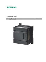
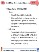
1.2 Application of the Module
DP Slave and AS-Interface Master
The CP 242-8 module can be operated in the S7* 200 programmable logic
controller. It allows the simultaneous attachment of an S7*200 to PROFIBUS DP
(as a DP slave) and to the AS-Interface (as AS-Interface master). Both network
attachments can be used independently of each other.
AS*i adapter
AS*i power supply unit
Active module
(with slave ASIC)
Passive module
(without slave ASIC)
AS-i
cable
Actuator/sensor
with slave ASIC
S7*200 CPU
Q0.0
Q0.1
Q0.2
Q0.3
Q0.4
Q0.5
I 0.0
I 0.1
I 0.2
I 0.3
I 0.4
I 0.5
I 0.6
I 0.7
SF
RUN
STOP
SIMATIC
S7*200
SIEMENS
CP 242-8
W
ider networking via PROFIBUS DP
SF
APF
CER
AUP
CM
AS-Interface
Master
CP
242
*2
6GK7 242
*2AX00*0XA0
1
2
3
4
5
6
7
8
0
9
10
11
12
13
14
15
16
17
18
19
20
21
22
23
24
25
26
27
28
29
30
31
X 2
3 4
DP slave /
AS-i master
Figure 1-1 Example of a System Setup with the CP 242-8
Technical Description and Installation Instructions
1-5
CP
242-8
AS-Interface Master / PROFIBUS DP Slave – Release 01
C79000–G8976–C109/01
System
Integration and Structure
Refer to the accompanying product information bulletin to find out the CPUs with
which the CP 242-8 can be operated.
From the point of view of the S7*200 CPU, the CP 242-8 is considered as two
expansion modules (one 8DI/8DO digital module and one 8AI/8AO analog
module).
In terms of installation, the CP 242-8 has the same technology as a standard
expansion module for an S7*200 station.
Power Supply
The CP 242-8 requires an external 24 V power supply for operation.
Components of the Product
The product CP 242-8 includes the following components:
S CP 242-8
S Bus connector
S Product Information for the CP 242-8
Technical Description and Installation Instructions
1-6
CP
242-8
AS-Interface Master / PROFIBUS DP Slave – Release 01
C79000–G8976–C109/01
1.3 Technical Specifications of the Module
The CP 242-8 module has the following technical specifications:
Table 1-1
Feature Explanation/Values
AS-i cycle time 5 ms with 31 slaves
Configuration of the AS-Interface By a button on the front panel
Supported AS-i master profiles M1
Connection of the AS-i cable Via a 7-pin terminal block
Permitted current loading from pin 1 to pin 3 or pin
2 to pin 4, maximum 3 A
Connection to PROFIBUS Via 9-pin sub D female connector
PROFIBUS address setting – Address range 1 to 126
– Set with SET and DISPLAY buttons
Permitted loading 5V DC at PROFIBUS connector max. 90 mA
Data rates supported (transmission rate) on
PROFIBUS
9.6 Kbps; 19.2 Kbps; 45.45 Kbps; 93.75 Kbps;
187.5 Kbps; 500 Kbps; 1.5 Mbps; 3 Mbps;
6 Mbps; 12 Mbps
Connection to an external 24 V power supply Via terminal block (7-pin)
Address range One digital module with 8DI/8DO and one analog
module with 8AI/8AO
Power supply from SIMATIC backplane bus
Current consumption from 5V DC
5 V DC
ma×. 340 mA
External power supply
Current consumption from 24 V
24 V DC (permitted range 20.4 to 28.8V DC)
ma×. 60 mA
Power supply from the AS-i cable
Current consumption from the AS-i cable
According to the AS-I specification
ma×. 100 mA
Power consumption 3.7 W
Ambient conditions
S Operating temperature Horizontal installation: 0 to 55°C
Vertical installation: 0 to 45°C
S Transportation and storage temperature – 40°C to +70°C
S Relative humidity max. 95% at +25°C
Construction
S Type of protection IP 20
S Module format S7-200 expansion module
S Dimensions (W x H x D) in mm 90 x 80 x 62
S Weight approx. 200 g
Technical Description and Installation Instructions
1-7
CP
242-8
AS-Interface Master / PROFIBUS DP Slave – Release 01
C79000–G8976–C109/01
1.4 Installing the Module
Slots in the S7-200
The CP 242-8 can be used in all slots for expansion modules on the S7-200
programmable controller.
Restrictions
There are, however, restrictions regarding the CPU or power supply used in terms
of the following:
S The expandability with more than one expansion module
For data on this topic, refer to /4/;
S The electrical design
The maximum current consumption from the S7 backplane bus must not be
exceeded. To calculate the current requirements, use the calculation table in
/4/.
Technical Description and Installation Instructions
1-8
CP
242-8
AS-Interface Master / PROFIBUS DP Slave – Release 01
C79000–G8976–C109/01
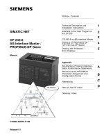
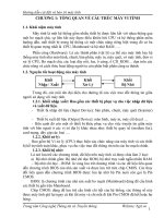
1.5 Front Panel – Access to all Functions
Connection,
Display and Control Elements
On the front panel, you have access to all the connection, display and control
elements of the CP 242-8.
During operation, connection and control elements are protected by a front cover.
SF
APF
CER
AUP
CM
CP 242-8
AS-Interface
Master
PROFIBUS DP Slave
1
2
3
4
5
6
7
8
0
9
10
11
12
13
14
15
16
17
18
19
20
21
22
23
24
25
26
27
28
29
30
31
X 2
3 4
DISPLAY
*
)
*
)
SET
1
PROFIBUS DP
BF
DIA
ADR
Connection Elements
(front cover open)
Control Elements
(front cover open)
Group Display
– 3 LEDs
Slave Display
– 5 LEDs
SET Button
– For AS-i configuration
– For setting the
PROFIBUS address
DISPLAY Button
– Changes over the display
Labeling Field
status display
Row of LEDs
with 8 two-color LEDs
(red/green or yellow/green)
for
– status display
or
– group/slave display
or
– PROFIBUS address display
Display elements
Mounting hole
for
wall installation
+
24 V –
6GK7 242-8DP00-0XA0
Figure 1-2Front Panel
Connections,
Operator Controls and Interpreting the Displays
For more detailed information, refer to the following sections.
Technical Description and Installation Instructions
1-9
CP
242-8
AS-Interface Master / PROFIBUS DP Slave – Release 01
C79000–G8976–C109/01
1.6 Connection Elements
Connections
The CP 242-8 has the following connectors:
S Two connectors to the AS-i cable (bridged internally)
S One connector for the external 24 V supply
S One connection for functional earth
S One connector to PROFIBUS (9-pin sub D female connector)
The connectors are located below the upper cover of the front panel of the CP
242-8.
–
+
–
+
1 PROFIBUS DP
AS-i cables
Functional ground
+ 24 V –
External 24 V supply
Figure 1-3 Connection of the AS-i Cable
Connections
to the AS-i cable
The CP 242-8 has two connectors for AS-i cables that are bridged internally in the
CP 242-8.
This allows the CP 242-8 to be looped into the AS-i cable.
!
Caution
The permitted current loading of the AS-i connection contacts is 3 A. If this value
is exceeded on the AS-i cable, the CP 242-8 must not be looped into the AS-i
cable but must be connected with a tap line (only one pair of connectors of the CP
242-8 is used).
Technical Description and Installation Instructions
1-10
CP
242-8
AS-Interface Master / PROFIBUS DP Slave – Release 01
C79000–G8976–C109/01
External
Power Supply
The CP 242-8 requires an external 24 V power supply (the permitted voltage range
is 20.4 to 28.8V DC). The current required from the 24 V supply is 60 mA.
With the AC and relay variants of the S7-200 CPUs, the sensor/transmitter supply
provided by the CPU can be used (see /4/).
Note
Functional ground
The CP 242-8 has a connector for functional ground. This connector should be
connected to the PE conductor with as little resistance as possible.
(terminal )
Connection
to PROFIBUS DP
Connection to PROFIBUS DP is via a 9-pin sub D female connector.
!
Warning
When laying and installing the PROFIBUS DP cable and the bus connector, follow
the instructions in /5/.
To attach to PROFIBUS DP, it is advisable to use bus connector 6ES7
972-0BA40-0XA0.
Technical Description and Installation Instructions
1-11
CP
242-8
AS-Interface Master / PROFIBUS DP Slave – Release 01
C79000–G8976–C109/01
1.7 Display and Control Elements
Meaning
of the ADR, BF and DIA LEDs
The front panel of the CP 242-8 has a row with 8 LEDs (see Figure 1-2). All the
LEDs are 2-color (red/green or yellow/green). The upper three LEDs (ADR, BF and
DIA) make up the group display. They indicate the display status.
Changing the Display Status – DISPLA
Y Button
The following figure shows the possible display statuses of the group display.
You can change between the status display, slave display and PROFIBUS address
display with the DISPLAY button. Each time you press the button, you change to
the next display status finally returning to the initial status.
ADR
BF
DIA
0 4 5 9 10 14 20 24 25 29 30 3115 19
PROFIBUS
address
display
red red/yellow or off
green
green or off
off
Change to the next display status
with the DISPLAY button
Status display
(initial status)
Display of the AS-i slaves
Key:
Technical Description and Installation Instructions
1-12
CP
242-8
AS-Interface Master / PROFIBUS DP Slave – Release 01
C79000–G8976–C109/01
1.7.1 Status Display
Interpreting
the Status Display
The status display is easily recognized because no group
LED is lit green. The ”ADR” LED must also not be lit red.
The status display is the default standard display in the
initial state of the CP 242-8.
The lower 7 LEDs indicate the status of the CP 242-8;
the label to the right of the LEDs then applies.
The bottom 5 LEDs indicate errors/states on the
AS-Interface. The BF and DIA LEDs indicate errors or
diagnostic messages on PROFIBUS DP.
Meaning
of the 7 Lower LEDs
When the status display is active, the LEDs have the following significance:
Table 1-2
LED (color) Status Meaning
BF (red) Bus Failure Indicates errors on PROFIBUS DP.
The LED is lit when:
S The connection between the DP master and the CP 242-8 has
broken down or the DP master is not active.
S The CP 242-8 was not or was incorrectly configured/assigned
parameters by the DP master.
DIA (yellow) Diagnostics The LED is lit when the CP 242-8 indicates diagnostic information to
the DP master.
Diagnostic information is reported by the CP 242-8 when the bit
PLC_RUN=0 (see Section 2.3.4 ); this is always the situation when
the S7-200 CPU is in the STOP mode.
SF (red) System error The LED is lit when:
S The CP 242-8 has detected an internal error (for example
EEPROM defective).
S The CP 242-8 cannot currently make the mode change requested
with the SET button (for example an AS-i slave with address 0
exists).
APF (red) AS-i Power Fail This indicates that the voltage supplied to the AS-i cable by the AS-i
power supply unit is too low or there is a complete power outage.
ADR
BF
DIA
red or off
off
yellow or off
Technical Description and Installation Instructions
1-13
CP
242-8
AS-Interface Master / PROFIBUS DP Slave – Release 01
C79000–G8976–C109/01
Table 1-2 , (continued)
LED (color) MeaningStatus
CER (yellow) Configuration
Error
This LED indicates whether the slave configuration detected on the
AS-i cable matches the expected configuration on the CP 242-8. If
they do not match, the CER LED is lit.
The CER LED is lit in the following situations:
S When a configured AS-i slave does not exist on the AS-i cable (for
example failure of the slave).
S When an AS-i slave exists on the AS-i cable but it was not
previously configured.
S When an attached AS-i slave has different configuration data (I/O
configuration, ID code) from the slave configured on the CP 242-8.
S When the CP 242-8 is in the offline phase.
AUP (green) Autoprog
available
In the protected mode of the CP 242-8, this indicates that automatic
address programming of an AS-i slave is possible. The automatic
address programming makes it much easier to exchange a defective
AS-i slave on the AS-i cable (for more detailed information refer to
Chapter 5.1).
CM (yellow) Configuration
Mode
This LED displays the mode of the CP 242-8.
S LED lit: Configuration Mode
S LED unlit: Protected Mode
The configuration mode is only required for installing and starting up
the CP 242-8. In the configuration mode, the CP 242-8 activates all
connected AS-i slaves and exchanges data with them. For more
information about the configuration mode, refer to Section 1.8.
Note
If there are no errors detected in the protected mode of the CP 242-8, all LEDs
are off.
Technical Description and Installation Instructions
1-14
CP
242-8
AS-Interface Master / PROFIBUS DP Slave – Release 01
C79000–G8976–C109/01
1.7.2 Slave Display for AS-i Slaves
Interpreting
the slave display status
The slave display can be recognized by the fact that at least
one group LED is lit green and that the ADR LED is not red.
The lower 5 LEDs then indicate the slaves on the
AS-Interface. In this case, the label to the left of the LEDs
applies. The display always represents 5 slaves.
Display Statuses and Operation in Detail
The AS-i slaves are displayed in groups of five. The upper three group LEDs
indicate (in green) which of the groups of 5 is displayed. The lower five LEDs are lit
green to indicate the detected or active AS-i slaves within the group.
S You can move from group to group by pressing the DISPLAY button again.
S The module returns to the status display in the following situations:
– After displaying the last group (AS-i slaves 30, 31) and pressing the
DISPLAY button twice. (In other words changing to the PROFIBUS address
display and then to the status display.)
– If you do not press the DISPLAY button for approximately 8 minutes.
Characteristics of the Slave Display
S If the CP 242-8 is in the configuration mode, all detected AS-i slaves are
displayed.
S If the CP 242-8 is in the protected mode, all active AS-i slaves are displayed.
In the protected mode, failed or existing but unconfigured AS-i slaves are
indicated by the corresponding LED flashing.
BF
DIA
ADR
green or off
green or off
green or off
Technical Description and Installation Instructions
1-15
CP
242-8
AS-Interface Master / PROFIBUS DP Slave – Release 01
C79000–G8976–C109/01
Example of a Slave Display
SF
APF
CER
AUP
CM
1
2
3
4
5
6
7
8
0
9
10
11
12
13
14
15
16
17
18
19
20
21
22
23
24
25
26
27
28
29
30
31
X
2
3 4
BF
DIA
ADR
Group Display
– 3 LEDs
Slave Display
– 5 LEDs
Display elements
CP 242-8
6GK7
242-8DP00-0XA0
Figure 1-4Example of a Slave Display
From the display you can obtain the following information:
S The group LEDs indicate the second group of five.
S Within this group, the active AS-i slaves 6 and 8 are displayed by the lower five
LEDs.
Technical Description and Installation Instructions
1-16
CP
242-8
AS-Interface Master / PROFIBUS DP Slave – Release 01
C79000–G8976–C109/01
1.7.3 Displaying and Setting the PROFIBUS Address
Interpreting the PROFIBUS Address Display
If the top LED (”ADR”) of the group display is lit up red, the 7
lower LEDs indicate the PROFIBUS address of the CP
242-8 in binary format.
Setting
the PROFIBUS Address
To set the PROFIBUS address of the CP 242-8, follow the steps outlined below:
1. Switch the S7-200 CPU to STOP. This ensures that bit PLC_RUN = 0.
Note
It is only possible to set the PROFIBUS address in this mode PLC_RUN = 0 (see
also Section 2.3.4)!
2. Change the display on the CP 242-8 until the ”ADR” LED is lit red by pressing
the DISPLAY button.
The CP 242-8 then indicates the currently set PROFIBUS address using the 7
lower LEDs.
3. If you now press the DISPLAY button, the CP 242-8 returns to the status
display, the set PROFIBUS address is retained.
If, on the other hand, you press the SET button, you can set a new value for the
PROFIBUS address. First of all, the ”BF” LED flashes and the most significant
bit of the PROFIBUS address is displayed.
4. If you press the SET button, this bit is set (LED on), if you press the DISPLAY
button, the bit is reset (LED off). The display then jumps to the ”DIA” LED (next
address bit of the PROFIBUS address).
5. By following the steps outlined above, you can now set or reset each of the
individual bits of the PROFIBUS address.
6. Once you have entered all the bits, the display of the set address bits flashes
changing quickly between red/green or yellow/green. If you press the SET
button again, the set PROFIBUS address is adopted by the CP 242-8. If, on the
other hand, you press the DISPLAY button, the new address is discarded. The
entry of the new address must then be repeated (as in steps 4 and 5).
ADR
BF
DIA
green or off
green or off
red
Technical Description and Installation Instructions
1-17
CP
242-8
AS-Interface Master / PROFIBUS DP Slave – Release 01
C79000–G8976–C109/01
The value of the address bits represented by the LEDs of the PROFIBUS address
is illustrated in the following example:
SF
APF
CER
AUP
CM
BF
DIA
ADR
Labeling field
status display
LED row
Value of the address bit
red
green
green
green
64
32
16
8
4
2
1
In the example,
the LEDs indicate the
PROFIBUS address:
64 + 4 + 1 = 69
Figure 1-5
In the example above, the PROFIBUS address 69 was set with the SET/DISPLAY
buttons.
The highest address that can be set is address 126. Remember that address 126
is reserved on PROFIBUS for special functions (address assignment). For data
exchange with a DP master, you can use addresses 1 to 125.