How electronic things workb P4
Bạn đang xem bản rút gọn của tài liệu. Xem và tải ngay bản đầy đủ của tài liệu tại đây (712.87 KB, 50 trang )
COLOR TV RECEIVER OPERATION 129
4
10
8
5
9
7
6
3
1
2
L505
8aH
Horiz. sweep & HV transformer
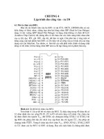
FIGURE 4-12
The Sencore’s OVM meter has input protection to measure the
Horizontal
Osc.
Driver
Output
Horiz. syn. input
B+ power supply
To ringer
Flyback transformer
FIGURE 4-13
The ringer test hook-up for finding shorts and open conditions
P-P high-voltage pulses in this horizontal sweep and high voltage circuit.
in a flyback transformer.
A “bad” reading, less than “10” rings, may be caused by a circuit connected to the fly-
back that is loading down the ringer test. Disconnect the most likely circuits in the follow-
ing order:
1 Deflection yoke.
2 CRT (picture tube). Unplug the socket connection.
3 Horizontal output transistor collector.
4 Scan-derived supplies.
Retest the flyback after you have disconnected each circuit. If the flyback now rings
“good,” it does not have a shorted winding.
If the flyback still checks out bad after you have disconnected each circuit, unsolder it
and completely remove it from the circuit. If the flyback primary still rings less than 10,
the flyback is defective and must be replaced.
Testing the high-voltage diode multipliers During normal TV/monitor operation, a
large pulse appears at the collector of the horizontal output transistor. The output connects
to the primary of the flyback transformer and the pulses are induced into the flyback’s sec-
ondary. The pulses are stepped up and rectified to produce the focus and high voltages.
These voltage pulses are rectified by high-voltage diodes contained in the flyback package
or in an outboard diode multiplier package.
Because these are high-voltage components, it is often difficult to determine dynami-
cally if the diodes will break down under high-voltage conditions. The Sencore analyzer
has a special test to determine if these diodes are good or bad.
HIGH-VOLTAGE PROBLEMS
It is only necessary to do this test if all of the following conditions are met:
1 The high voltage or focus voltage is low or missing.
2 The B+ and peak-to-peak voltages at the horizontal transistors are normal.
3 The horizontal sweep (flyback) transformer passes the ringer test.
With the analyzer, feed a 25-volt peak-to-peak horizontal sync drive signal into the pri-
mary winding of the flyback transformer. The step-up section of the transformer and the
high-voltage diodes should develop a dc voltage between the second anode and high-voltage
resupply pin on the flyback transformer. Measure this voltage with a dc voltmeter. Look up
this voltage on the schematic to determine if the high-voltage diodes are good or bad.
HORIZONTAL OSCILLATOR, DRIVER,
AND OUTPUT PROBLEMS
If the horizontal yoke, flyback, multiplier, horizontal output transistor, and B+ supply have
tested good, but the TV still lacks deflection or high voltage, the horizontal driver circuit might
be defective. A missing or reduced-amplitude horizontal drive signal could prevent the TV
130 HOW COLOR TVS AND PC MONITORS WORK
from starting and operating properly. Use the Sencore analyzer’s horizontal drive signal to iso-
late problems in the horizontal drive circuit. Refer to the signal injection points in Fig. 4-14.
TV start-up problem
1
Before injecting into the horizontal drive circuit, test the flyback and yoke, the high-
voltage multiplier, the horizontal output transistor, and the +3
-
V supply.
2 When injecting at the output transistor, disconnect the secondary winding of the driver
transformer from the base.
Inject the horizontal drive signal into the driver circuit. Watch for horizontal deflection
on the picture tube. If it returns, you are injecting after the defective stage. If nothing hap-
pens, inject the horizontal drive signal at the base of the horizontal output transistor. Refer
to Fig. 4-15 for these injection points.
COLOR TV RECEIVER OPERATION 131
Horizontal stages
Inject horizontal
test pulses into
horizontal driver
circuit
Horizontal sync.
Osc.
Driver
Output
To horizontal output stage
FIGURE 4-14
The injection points for test pulse injection into the
50
51
52 53
Horizontal
Inject horizontal sync.
H
orizontal sync.
Osc.
Driver
Output
B+
Power
supply
Yo k e
Multiplier
Flyback
1
FIGURE 4-15
Horizontal drive signal test injection points. The base of the
horizontal driver circuit.
output driver transistor is a good injection point.
How to measure the TV’s high voltage The picture tube (CRT) requires a very high dc
voltage to accelerate the electrons toward the screen of the CRT. This voltage is developed
in the secondary winding of the flyback transformer and is amplified and rectified by the
integrated diodes in the flyback, or by a separate multiplier circuit.
Measuring the high voltage at the second anode of the picture tube lets you know if the
output circuit, sweep transformer, high-voltage multiplier, and power-supply regulation
circuits are working properly. Additionally, some TVs and computer monitors have adjust-
ments for setting the high voltage and focus voltage correctly.
Use extreme care when measuring and adjusting any voltage around the picture tube
and high-voltage power supplies.
Blurred, out-of-focus picture symptom For this problem, first measure the picture-tube
high-voltage capacitor with a high-voltage probe. Compare these readings with the HV
readings shown in the schematic. Also, if these voltages are OK, check the focus voltage
and suspect that the CRT is weak.
Switching transformer checks Switching transformers are used in power-supply cir-
cuits to step voltages up or down. They are one of the most common components to fail in
switch-mode power supplies. Open windings are easy to find with an ohmmeter, but
shorted turns are nearly impossible to locate with conventional test methods. The Sencore
video analyzer’s ringer test helps you to locate switching transformer with open or shorted
windings.
For this test, the switching transformer must be removed from the TV’s circuit.
To perform this test, connect the Sencore analyzer ringer test leads across a winding on
the switching transformer. A reading of 10 rings or more will show that the winding does
not have a shorted turn. Perform this same test on all windings of the switching trans-
former.
THE VERTICAL SWEEP SYSTEM
In my feedback from many electronic technicians, most say that the vertical sweep sys-
tems are among the most difficult circuits in a monitor or TV to troubleshoot. Even the
most small change in a component can cause reduced sweep deflection, nonlinear deflection,
or picture fold-overs. These symptoms can be caused by a small circuit part or an expensive
vertical yoke. Thus, you must think carefully of a strategy to take the guesswork out of iso-
lating vertical sweep problems.
How vertical deflection works Knowing how the vertical sweep deflection circuits oper-
ate requires an understanding of picture tube beam deflection. The electron beam travels to
the face of the picture tube striking the phosphor surface coating to produce light on the front
of the picture tube.
132 HOW COLOR TVS AND PC MONITORS WORK
If the stream of electrons travels to the face plate of the tube without any control from
any magnetic or electrostatic field, the electrons will strike the center of the screen and
produce a white dot. To move this dot across the face of the picture tube screen requires
that the electrons be influenced by an electrostatic or magnetic field.
In video display tubes, a magnetic field is produced by the vertical coils of a yoke
mounted around the neck of the tube. The yoke is constructed with coils wound around a
magnetic core material.
When current flows in the vertical yoke coil windings, a magnetic field is produced. The
yoke’s core concentrates the magnetic field inward through the neck of the picture tube.
As the electrons pass through the magnetic field on the way to the tube’s face plate, they
are deflected (pulled upward or downward) by the yoke’s changing magnetic field. This
causes the electron stream to strike the picture tube face plate at points above and below
the screen center.
To understand how electrons are deflected requires a review of the interaction of mag-
netic fields. As you refer to Fig. 4-16A and 4-16B, you might recall that an individual elec-
tron in motion is surrounded by a magnetic field. The magnetic field is in a circular motion
surrounding the electron. As electrons travel through the magnetic field of the yoke, the
magnetic fields interact. Magnetic lines of force in the same direction create a stronger
field, but magnetic lines in opposite directions produce a weaker field. The electrons are
then pulled toward the weaker field.
The direction of the current in the yoke coil determines the polarity of the yoke’s mag-
netic field. This determines if the electron beam is deflected upward or downward.
How far the electrons are repelled when passing through the yoke’s magnetic field is
determined by the design of the yoke and the level of current flowing through the ver-
tical coils. The higher the current, the stronger the magnetic field and resulting electron
deflection.
A requirement of vertical sweep deflection in a TV or monitor is that the current in the
coils of the vertical yoke increase an equal amount for specific time intervals. This linear
COLOR TV RECEIVER OPERATION 133
Time
Yoke current
current
+
0
Electron beam
Electron beam magnetic field
Time
Yoke current
current
+
0
Electron beam deflection path
Deflection yoke magnetic field
A
B
FIGURE 4-16
The yoke mounted on the CRT neck produces the magnetic
field, resulting in electron beam deflection.
current change causes the deflection of the electron beam from the top to the center of the
picture tube faceplate.
The waveforms shown in Fig. 4-16A and 4-16B represent a current increasing and decreas-
ing in level, with respect to time. Figure 4-16A shows the current increasing quickly and
then decreasing slowly back to zero. This would cause the electron beam to quickly jump
to the top of the picture tube screen and then slowly drop back to the center.
Figure 4-16B shows the current increasing slowly in the opposite direction and then
decreasing quickly back to zero. This would cause the electron beam to slowly move from
the center to the bottom of the picture tube faceplate and then return quickly to the center.
During normal TV or monitor operation, the yoke current increases and decreases
(Fig. 4-16A and 4-16B). The current changes directions alternating between the illustra-
tions at approximately 60 times per second. The alternating current moves the electron
beam from the top of the picture tube faceplate to the bottom and quickly back to the
screen’s uppermost area.
How the vertical drive signal is developed The vertical circuit stages of the TV are
responsible for developing the vertical drive signals. This signal is fed to an output ampli-
fier, which produces alternating current in the vertical deflection yoke.
The vertical section consists of four basic circuits or blocks (Fig. 4-17). These include:
1 Oscillator or digital divider.
2 Buffer/pre-driver amplifier.
3 Driver amplifier.
4 Output amplifier.
The circuitry for these stages can be discrete components on the circuit board or might
be included as part of one or more integrated circuits.
134 HOW COLOR TVS AND PC MONITORS WORK
Oscillator
Buffer
predriver
Driver
Output amp
Vertical size
Vertical hold
Vertical linearity
Feedback
Cs
Rs
Vertical yoke coils
FIGURE 4-17
The vertical section of a TV receiver consists of
an oscillator, buffer, driver, and output amplifier.
The vertical oscillator generates the vertical sweep signal. This signal is then fed to the
amplifiers and drives the yoke to produce deflection. Vertical oscillators can be free run-
ning or the more modern digital divider generators.
These free-running oscillators use an amplifier with regenerative feedback to self gener-
ate a signal. More common types are RC (resistance-capacitance) oscillators associated
with ICs or discrete multivibrator or blocking oscillator circuits.
A digital divider generator uses a crystal oscillator. The crystal produces a stable fre-
quency at a multiple of the vertical frequency. Digital divider stages divide the signal
down to the vertical frequency. You will usually find most of the digital divider oscillator
circuitry located inside an integrated circuit.
The output of a vertical oscillator must be a sawtooth-shaped waveform. A ramp genera-
tor is often used to shape the output waveform of a free-running oscillator or digital divider.
A ramp generator switches a transistor off and on, alternately charging and discharging
a capacitor. When the transistor is off, the capacitor charges to the supply voltage via a
resistor. When the transistor is switched on, the capacitor is discharged.
The vertical oscillator must then be synchronized with the video signal so that a locked-
in picture can be viewed on the picture tube. The oscillator frequency is controlled in two
ways.
1 A vertical hold control might be used to adjust the free-running oscillator close to the
vertical frequency.
2 Vertical sync pulses, removed from the video signal, are applied to the vertical oscilla-
tor, locking it into the proper frequency and phase.
If the oscillator does not receive a vertical sync pulse, the picture will roll vertically. The
picture will roll upward when the oscillator frequency is too low and downward when the
frequency is too high.
Several intermediate amplifier stages are between the output of the vertical oscillator
and output amplifier stage. Some common stages are the buffer, predriver, and/or driver.
The purpose of the buffer amplifier stage is to prevent loading of the oscillator, which
could cause frequency instability or waveshape changes.
The predriver and/or driver stages shape and amplify the signal to provide sufficient
base drive current to the output amplifier stage. Feedback maintains the proper dc bias and
waveshape to ensure that the current drive to the yoke remains constant as components,
temperature, and power-supply voltages drift. These stages are dc coupled and use ac and
dc feedback, similar to audio amplifier stages.
Notice that ac feedback in most vertical circuits is obtained by a voltage waveform derived
from a resistor placed in series with the yoke. The small resistor is typically placed from
one side of the yoke to ground. A sawtooth waveform is developed across the resistor as
the yoke current alternates through it. This resistor provides feedback to widen the fre-
quency response, reduce distortion, and stabilize the output current drive to the yoke. This
vertical stage feedback is often adjusted with gain or shaping controls, referred to as the
vertical height or size and vertical linearity controls.
The dc feedback is used to stabilize the dc voltages in the vertical output amplifiers. The
dc voltage from the output amplifier stage is used as feedback to an earlier amplifier stage.
Any slight increase or decrease in the balance of the output amplifiers is offset by slightly
COLOR TV RECEIVER OPERATION 135
changing the bias. Because the amplifier’s waveforms are slightly distorted, the bias
change will shift the bias on the output transistors, somewhat, thus bringing the stage back
into compliance.
Much of the difficulty in troubleshooting vertical stages is caused by the feedback and dc
coupling between stages. A problem in any amplifier stage, yoke, or its series components
alters all of the waveforms and/or dc voltages, making it difficult to trace the problem.
Vertical picture-tube scanning The vertical output stage produces yoke current that
then pulls the electron beam up and down the face of the picture tube. The vertical yoke
might require up to 500 mA of alternating current to produce full picture tube deflection.
A power output stage is now required to produce this level of current.
A current output stage commonly consists of a complementary symmetry circuit with
two matched power transistors (Fig. 4-18). The transistors conduct alternately in a push-
pull arrangement. The top transistor conducts to produce current in one direction to scan
the top half of the picture. The bottom transistor conducts to produce current in the oppo-
site direction to scan the bottom part of the picture.
Most vertical output stages are now part of an IC package and are powered with a single
positive power supply voltage. The voltage is applied to the collector on the top transistor.
136 HOW COLOR TVS AND PC MONITORS WORK
Cs
Rs
Qb
Qt
B+
Cs
Rs
Qb
Qt
B+
Cs
Rs
Qb
Qt
B+
Cs
Rs
Qb
Qt
B+
Yoke current
Output voltage
Time A
Time B Time C Time D
FIGURE 4-18
The deflection currents and waveforms during four time periods
of the vertical cycle.
In this balanced arrangement, the emitter junction of the transistor should measure about
one half of the supply voltage on this stage. In series with the vertical yoke coils is a large-
value electrolytic capacitor. This capacitor passes the ac current to the yoke, but blocks dc
current to maintain a balanced dc bias on the output amplifier transistors.
To better understand how a typical vertical output stage works, let’s walk through the
current paths at four points in time, during the vertical cycle illustrated in (Fig. 4-18).
Starting with time A, the top transistor, Qt is turned on by the drive signal to its base. The
transistor is biased on, resulting in a low conduction resistance from collector to emitter,
which provides a high level of collector current. This puts a high plus (+) voltage potential
at the top of the deflection yoke, resulting in a fast rising current in the yoke.
During time A, capacitor Cs charges toward a positive (+) voltage and current flows
through the yoke and the top transistor, Qt. This pulls the picture tube’s electron beam
from the center of the picture tube up quickly to the top. During time A, an oscilloscope
connected at the emitter junction displays a voltage peak, shown as the voltage output
waveform in Fig. 4-18. The inductive voltage from the fast-changing current in the yoke
and the retrace “speed-up” components cause the voltage peak to be higher than the posi-
tive (+) power supply voltage.
The current flowing in the deflection yoke during time A produces a waveform, as
viewed from the bottom of the yoke to ground. This is the voltage drop across Rs, which
is a reflection of the current flowing through the yoke.
During time B, the drive signal to Qt slowly increases the transistor’s emitter-to-collector
resistance. Current in the yoke steadily decreases as the emitter-to-collector (E-C) resistance
increases and thus reduces the collector current. The voltage at the emitter junction falls
during this time and capacitor Cs discharges. A decreasing current through the yoke causes
the picture tube’s electron beam to move from the top to the center of the screen.
To produce a linear fall in current through the yoke during time B demands a crucially
shaped drive waveform to the base of Qt to meet its linear operating characteristics. The
drive waveform must decrease the transistor’s base current at a constant rate. Thus, the
transistor must operate with linear base-to-collector current characteristics. These reduc-
tions in base current must result in proportional changes in collector current.
At the end of time B, transistor Qt’s emitter-to-collector resistance is high and the tran-
sistor is approaching the same emitter-to-collector resistance as the bottom transistor, Qb.
Capacitor Cs has been slowly discharging to the falling voltage at the emitter junction of
the output transistors. Just as the voltage at the emitter junction is near one half of the pos-
itive (+) supply voltage, the bottom transistor begins to be biased ON to begin time C. This
transition requires that the conduction of Qt and Qb at this point be balanced to eliminate
any distortion at the center of the picture-tube screen.
During time “C”, the resistance from the collector to emitter of transistor Qb is slowly
decreasing because of the base drive signal and the increase of collector. The signal passes
from capacitor Cs through the yoke and Qb. As Qb’s resistance decreases and its collector
current increases, the voltage at the emitter junction decreases. This can be seen on the
voltage output waveform as it goes from one half positive (+) supply voltage toward
ground during time C. The current increases at a linear rate through the yoke, as shown in
the yoke current or voltage across Rs waveform (Fig. 4-18).
The resistance decrease of Qb must be the mirror opposite of transistor Qt’s during time
B. If not, the yoke current would be different in amplitude and/or rate, causing a difference
COLOR TV RECEIVER OPERATION 137
in picture-tube beam deflection between the top trace and bottom trace times. At the end
of time C, the emitter-to-collector resistance of Qb is low and Qb is slowly decreasing by
the base increase of collector begins to discharge, producing current as the deflection yoke
approaches a maximum level.
At the start of time D, the emitter-to-collector resistance of Qb is increased rapidly
and collector current will decrease. This quickly slows the discharging current from
capacitor Cs through the yoke and transistor. As the current is reduced, the trace is
pulled quickly from the bottom of the screen back to its center. Time A begins again and
the cycle is repeated again. This should now give you an overall view of how the hori-
zontal and vertical sweep and scanning system produces a picture on your TV or com-
puter monitor.
The basic inner workings of the color TV and PC monitor have now been covered. Another
very important part of the color TV is the portion that you look at, the picture tube (cathode-
ray tube or CRT).
The working of the color picture tube The CRT works by producing (emitting) steady
flow of electrons from the electron gun at the base (neck) of the CRT. These electrons are
attracted to and strike the phosphor-coated screen of the CRT, causing the phosphors to
emit light. Deflection circuits and a yoke outside the CRT produce a changing magnetic
field that extends inside the CRT and deflects the beam of electrons to regularly scan
across the entire face of the CRT, lighting the entire screen. The CRT can be divided into
three functional parts (Fig. 4-19):
1 The electron gun cathode assembly.
2 The electron gun grids.
3 The phosphor screen and front plate.
The color picture tube is the last component in the video chain that lets you actually view
a color picture on your TV or monitor. The major sections of a color set have previously
been explained in this chapter, so now see how the CRT develops a color picture.
138 HOW COLOR TVS AND PC MONITORS WORK
Red gun
Green gun
Blue gun
Deflection yoke
Shadow mask
Beam convergence
at shadow mask
Phosphor dots
on glass faceplate
FIGURE 4-19
An inside
view drawing of a picture
tube that has an in-line gun
assembly, metal dot mask,
and phosphor dot triads on
a glass faceplate.
Color CRTs use a metal shadow mask, phosphor screen, and three electron guns to pro-
duce red, blue, and green (RBG) colors that can produce a full color picture. These three
colors are produced from phosphors that are excited by electron beams coming from three
different guns, one gun for each of the (RBG) colors.
Figure 4-19 shows the relationship between shadow mask, electron guns, and the phos-
phors on the tube’s faceplate. As you refer to Fig. 4-20A, notice that each beam converges
through a hole in the shadow mask, while approaching the hole at a slightly different angle.
Because of these different angles, the red beam hits the red phosphor, the blue beam the
blue phosphor, and the green beam hits the green phosphor. However, each beam strikes
more than one hole (Fig. 4-20B). With signals from the TV’s red, green, and blue demod-
ulators, these three electron beams are then mixed (matrixes) to different proportions to
produce a very wide range of spectrum colors and intensities.
Over the years, TVs and monitors have used various types of picture-tube construction.
The first color picture tubes used a delta gun arrangement with a dot shadow mask. As
shown in Fig. 4-20A and 4-20B, the metal mask has evenly spaced holes with RGB phos-
phors clustered on the glass faceplate in groups of three. However, this triad arrangement
had convergence problems because the three beams could not be made to meet at the
shadow mask holes for certain areas of the faceplate.
How the electron CRT gun works The electron gun consists of several different parts
that together create, form, and control the electron beam. These parts are the filament
(heater), cathode (K), the screen grid (G1), and the screen grid (G2). A monochrome (sin-
gle color) CRT has just one electron gun, and a color CRT has three separate electron
guns—one each for each color: red, green, and blue.
The cathode (K) is the source of the electrons, which are attracted to the screen. The
cathode in most picture tubes look like a tiny tin can with one end cut out. It is coated with
a material (such as barium or thorium) that emits large numbers of electrons when heated
to a high temperature with the filament.
COLOR TV RECEIVER OPERATION 139
R
G
B
Screen
Shadow mask
Blue axis
Red axis
Green axis
Phosphor dots (triads)
Screen
Shadow mask
Phosphor dots (triads)
Red beam
A
B
FIGURE 4-20
Shown in A is convergence of the blue, green, and red electron
beams at the shadow mask. In B, each beam illuminates more than one
phosphor triad.
Several grids in front of the cathode attract the electrons away from the cathode toward
the phosphor screen, control the rate of electron flow, and shape the cloud of electrons into
a sharply focused beam.
The filament is mounted inside the cathode, and resembles the filament in a light bulb.
The filament is used to heat the cathode. The filament is also called the tube heater. The
filament is insulated from the cathode and does not make electrical contact.
The control grid is used to control the electrons. Without the control grid, the electrons
would quickly leave in one big cloud with no control. The operation of the control grid can
be compared to how a water faucet controls the flow of water.
GE in-line electron gun General Electric developed the in-line gun with the slotted shadow
mask in the mid 1970s. The metal mask has vertical slots instead of holes and the phosphors
on the glass faceplate are RGB vertical strips, instead of dot triodes. The advantage of the
in-line gun (Fig. 4-21) is simplification of convergence adjustments and a brighter picture
level. When mated with properly designed yokes, the color convergence is considerably sim-
plified. The Trinitron picture tube, invented and developed by the Sony Corporation, has a
similar in-line design, except it has a three-beam electron gun and the shadow mask has a
series of strips. The three common CRT gun patterns are in-line, delta, and Trinitron (Fig. 4-22).
In most cases, TV images are usually blobs of intensity and color. When a camera pans
from one object to another, they are fuzzy because of bandwidth limitations of the video
signal. In most cases, the images on computer displays consist of lines with sharp transi-
140 HOW COLOR TVS AND PC MONITORS WORK
FIGURE 4-21
This photo shows the GE in-gun assembly and the adjustments
used for convergence.
tions of luminance. Usually the in-line/strip and slotted-mask CRT provides excellent pic-
tures, but the in-line gun/dot mask-construction design displays text and graphics much
better. A PC monitor color picture tube gun and socket assembly is shown in Fig. 4-23.
Color picture tube summation A color TV contains all of the circuitry of the mono-
chrome receiver, plus the added circuits needed to demodulate and display the color por-
tion of the picture. To display the picture in color, three video signals are derived: the
original red, green, and blue video signals.
The color CRT contains three color phosphors, each of which glows with one of the
three primary colors when bombarded by electrons. These phosphors are placed on the in-
ner surface of the picture tube faceplate as either triangular groups of the three colors (used
in older models), alternating rectangles of the three colors, or alternating stripes of the
three colors. Regardless of the version, all color tubes require three separate electron
beams, each modulated with the video of one of the primary colors. All color tubes have
some type of shadow mask placed behind the phosphors. This mask has a series of open-
ings that allow each electron beam to strike only the correct color of phosphor.
The three beams must be precisely aligned to enable them to enter the opening in the
mask at the correct angle and strike the correct phosphor. Stray magnetic fields could
create enough error to cause the incorrect color to be displayed in parts of the picture. For
this reason, color TVs have a coil mounted around the CRT faceplate and an automatic
degaussing circuit to keep the picture tube and other nearby metal parts demagnetized.
Sometimes when a TV is moved to another location, the picture tube might have to be
manually degaussed to clean up the color picture (Fig. 4-24).
LARGE-SCREEN PROJECTION TV OPERATION
Large-screen projection TVs are now produced in many screen sizes and price ranges. Most
have provisions for “surround-sound” audio amplifier systems, audio/video, and cable TV
COLOR TV RECEIVER OPERATION 141
Trinitron
Delta
In-Line
Phosphor
Shadow mask
M
agnification
Electron beam
FIGURE 4-22
The three phosphor patterns for Trinitron (Sony), delta, and in-line
picture tube formats.
142 HOW COLOR TVS AND PC MONITORS WORK
FIGURE 4-23
The picture
FIGURE 4-24
A degaussing coil being used to demagnetize a color TV
tube socket and PC board
assembly.
picture tube faceplate.
and DBS dish input connections. A front view of a typical large-screen projection set is
shown in Fig. 4-25. This type of TV projects the picture image onto the back of a translucent
(Fresnel) screen that can then be viewed from the front. As shown in Fig. 4-26, the inside
view these sets have three separate red, green, and blue (RGB) projection tubes to produce
a bright picture.
A front-screen projection TV is illustrated in Fig. 4-27. These sets also use three sepa-
rate red, green, and blue tubes to throw an image on a beaded projection screen, usually
mounted on a wall.
In large-screen projection sets, high-definition, liquid-cooled projection tubes are used
to provide a bright, high-resolution, self-converged picture display. Optical coupling is
used between the projection tubes and the projection optics for display contrast enhance-
ment. A screen with high-gain contrast and an extended viewer angle are now used on the
newer-model projection receivers. Also, fault-mode sensing and electronic shutdown cir-
cuits are provided to protect the TV in the event of a circuit fault mode or picture tube arc.
Some projection TV system details For their optics, some projection TVs use three
U.S. precision lens (USPL) compact delta 7 lenses. This new lens, designed by USPL,
incorporates a lightpath fold or bend within the lens assembly. This is accomplished
with a front surface mirror that has a lightpath bend angle of 72 degrees. Because of
this lightpath bend, the outward appearance of the lens resembles, somewhat, that of
the upper section of a periscope. The lens elements and the mirror are mounted in a
plastic housing. Optical focusing is accomplished by rotating a focus handle with wing
lock-nut provisions. Rotation of the focus handle changes the longitudinal position of
the lens’ B element.
COLOR TV RECEIVER OPERATION 143
AC
311
TEL 555-2368
Open panel door
for access to
secondary controls
FIGURE 4-25
The front view of a typical projection color TV receiver.
Projection set lightpath profile A side view of the TV lightpath is shown in Fig. 4-28. Note
the tight tuck of the lightpath provided by the Delta 7 compact optics. For comparison pur-
poses, the lightpath profile of an earlier model projection set is shown in Fig. 4-29.
Liquid-cooled projection tubes The rear-screen projection TVs use three projection
tubes (R, G, and B) arranged in a horizontal-in-line configuration. This type of config-
144 HOW COLOR TVS AND PC MONITORS WORK
Speaker
Speaker
RGB crt gun assy
FIGURE 4-26
A front view
FIGURE 4-27
Drawing of a front screen projection TV set. This unit can set on
with viewing screen removed of a
rear projection color TV set,
showing component locations.
a table or be hung from the ceiling. Many of this units are used in home theater
installations.
uration uses two (red and blue) slant-face tubes and one (green) straight-face tube. All
tubes are fitted with a metal jacket housing with a clear glass window. The space between
the clear glass window and the tubes faceplate is filled with an optical clear liquid. The liq-
uid that is heat-linked to the outside world, prevents faceplate temperature rise and thermal
gradient differentials from forming across the faceplate when under high-power drive sig-
nals. With liquid-cooled tubes, the actual safe power driving level can be essentially dou-
bled over that of the older nonliquid-cooled tubes. This is highly desirable in terms of the
large-screen picture brightness. The late-model sets use an 18-watt drive level to the pic-
ture tube, but the older-model projection sets had only an 8.5-watt drive level.
A side view of the jacket/tube assembly is shown in Fig. 4-30. The metal jacket shell
extends back, well over the panel to the funnel seal and thereby functions as an effective x-ray
COLOR TV RECEIVER OPERATION 145
Phosphor plane
Upper mirror
R
ear screen
72°
FIGURE 4-28
A side view of
Lens
Upper mirror
Viewer
L
ower mirror
Phosphor image
Rear projection screen
FIGURE 4-29
A side view of the light path and
the light path of a projection TV
receiver.
(Zenith)
mirrors of a projection TV. (Zenith)
shield. The metal jacket also serves as the mechanical mounting and support for the picture
tube assembly. The front of the metal jacket is elongated and the mounting holes are placed
in the elongated sections. This is purposely done to permit the tightest possible tube-to-tube
spacing for in-line tube placement.
Optical picture tube coupling A pliable optical silicone separator is mounted between
the glass window on the liquid-cooled jacket assembly and the rear element of the Delta 7
lens. When under mounting pressure, the silicone separator makes close contact with these
two lightpath interconnecting surfaces.
Self-convergence design Many large-screen projections have self-convergence and
automatic convergence features. Final touch-up convergence can also be made with the
remote control when in the service or set-up mode. This is accomplished in the receiver
with the tilted faceplate of the red and blue tubes, in combination with shifted red and
blue pointing angles, are image offsets that are used to provide for three-image conver-
gence. This combination is required because of the shorter focal length in the Delta 7
lens design and its incompatibility with existing faceplate tilt angles. Because the
receiver is a self-convergence system, registration of only the three images will be
required. This is accomplished with special circuits located in the raster registration PC
module.
Picture brightness and projection screen Usually, the projection screen for these
projection sets is a two-piece assembly. The front (viewer side) piece will be a vertical
lenticular black-striped section. The rear piece is a vertical off-centered Fresnel section.
The black striping not only improves initial contrast, but also enhances picture bright-
ness and quality for greater viewer enjoyment under typical room ambient lighting con-
ditions.
The newer-large screen receivers demonstrate increased picture brightness over previ-
ous projection TVs. This is made possible by the use of liquid-cooled projection tubes and
their ability to accommodate higher-power drive signals. The improvements will be sub-
stantial and some projection sets run almost twice the brightness level as the older models.
Figure 4-31 shows the location of the circuit board modules and where the projection tubes
are mounted in a late-model projection TV.
146 HOW COLOR TVS AND PC MONITORS WORK
Glass window
Front panel of bulb
Liquid coolant (no leaks allowed)
Inside glass defined
FIGURE 4-30
Drawing of a liquid-cooled CRT assembly.
What To Do When
Your TV Has Problems
Some of the TV troubles were covered in the last portion of this chapter. Some of the trou-
ble symptoms will be photos taken from the actual TVs with the problem. Some of the
other problems are within the TV.
PROBLEMS AND WHAT ACTIONS YOU CAN TAKE
The symptom The set will not operate (no sound or picture, dark screen).
What to do:
■ Check the ac power outlet with an ac meter or plug in a known-working lamp. If no ac
power is found, check and/or reset the circuit breaker to this outlet.
■ Check the ac line cord and plug from TV to the wall outlet. Some older TVs might have
an interlock plug that removes ac power from the set when the back is removed. Be sure
that this interlock plug is making a good connection.
■ Check and/or reset the circuit breaker on back of a TV. Other sets will have a main
power fuse located on the chassis. Check fuse with a ohmmeter. Replace any blown
fuse with same current (amp) rating as the blown (open) fuse. If the fuse blows again,
the set probably has a shorted rectifier diode in the power supply or some other circuit
is shorted or drawing too much current.
■ Check the on/off switch for proper mechanical operation. Use an ohmmeter to see if the
switch is working (on and off contact) electrically.
WHAT TO DO WHEN YOUR TV HAS PROBLEMS 147
L
eft speaker Right speaker
9-259-02
Axis correction
9-387-07
IF & audio
9-153-10
Sweep
9-152-09
Chroma, luma, vert.
9-500-01
SMPS
9-180-01
Raster
registration
9-155-31
Video
output
9-155-31
Video
output
9-155-31
Video
output
9-179-01
A-9120-03 Distributor
175-2275
Tuner
A-13779
Jack pack
9-524-03
Video
input
9-253-03
Stereo decoder
Red
crt
Green
crt
Blue
crt
A-14037
Secondary control
A-12752-05
AFC switch
9-417-01
Stereo
interface
85-1735
Membrane keyboard
9-442
Tuner
control
FIGURE 4-31
Circuit modules and picture tube locations of a typical color TV
projection set.
The symptom The TV has no sound or picture. The set produces a smooth white picture
(Fig. 4-32).
What to do:
■ Check the TV cable, antenna lead in, cable lead from DBS antenna, and be sure that all
of these cable connections are good and tight. Replace the coax cable and connections
if it is found defective.
■ Inside the TV is a separate tuner box that will have a shielded cable that plugs into the
main chassis. Check this cable for clean, tight connections.
■ For older TVs, the tuner knob will turn and click. This indicates that it is a mechanical
tuner with switch contacts. Dirty or corroded contacts can cause a loss of picture and
sound. Remove the tuner cover and spray the contacts with a tuner cleaner and lubricant.
When working inside a TV, always be very careful because high voltage is present.
■ Some TVs have a control, usually on the back, labeled AGC (Automatic Gain Control). If
this control is misadjusted, the picture and sound will be missing. Try readjusting the AGC.
The symptom Picture width reduced (pulled in from the sides, as shown in Fig. 4-33).
What to do:
■ Check the dc voltage from power supply. If not correct, readjust the B+ level control if
the set has one.
■ A shorted coil winding in the horizontal sweep transformer or deflection yoke could
cause this problem.
The symptom Very bright narrow horizontal line across the screen. This problem is
caused by the loss of vertical sweep.
148 HOW COLOR TVS AND PC MONITORS WORK
FIGURE 4-32
The symptom for this TV set’s problem
is a blank (white) screen and no sound.
What to do:
■ Check and adjust the vertical hold control.
■ Check, clean, and/or adjust vertical height and linearity controls.
■ Check vertical oscillator and output transistors and or IC stages.
■ Check lead-wire plugs or solder connections to the deflection yoke.
■ The loss of vertical sweep could also be caused by an open vertical coil winding in the
deflection yoke, which is mounted on the neck of the picture tube.
The symptom The picture is reduced at top and bottom (Fig. 4-34). This is also a verti-
cal sweep problem.
WHAT TO DO WHEN YOUR TV HAS PROBLEMS 149
FIGURE 4-33
The picture (raster) is pulled in from
both sides of the screen.
FIGURE 4-34
The picture pulled down from top and
bottom. This is usually a vertical sweep circuit problem.
What to do:
■ Check the vertical sweep output stage components.
■ It could also be a shorted winding in the vertical coils of the deflection yoke. This might
show up as keystone raster shape.
■ Check and adjust the vertical hold control.
■ Check and adjust vertical size and linearity controls.
■ Some sets have a vertical centering control. If your set has one, check and adjust it
because a defective centering control will cause the picture to shrink down in size.
■ Check for low dc voltages in the set’s power supply and in the vertical sweep stages.
■ Check out any of the large (electrolytic) capacitors in the vertical sweep stage or that
couple this stage to the deflection yoke. To make a quick check, just bridge another
good capacitor across the suspected one and see if the picture fills out.
■ A large black bar at the top or bottom of the picture tube could be caused by some type
of RF noise interference. Change channels and if this black bar disappears, that is your
problem. A problem in the cable system could cause this same symptom.
The symptom Small horizontal black lines appear across the picture and it might tend to
weave (Fig. 4-35).
What to do:
■ The power supply might have poor low voltage regulation or faulty filter capacitors.
Check B+ voltage with a meter and adjust the voltage level if your set has an B+ adjust-
ment control. This symptom could also be caused by some type of signal interference.
150 HOW COLOR TVS AND PC MONITORS WORK
FIGURE 4-35
Small narrow black lines appear across
the screen, and the picture might bend or weave.
■ The degaussing circuit might not be turning off after the TV warms up. Check it by
unplugging the degaussing coil that goes around inside the picture tube faceplate. The
thermal resistor or diode in the power supply might be defective.
The symptom An arcing or popping sound. This is usually around the large red HV lead
and rubber cup on the picture tube. Also, in and around the HV sweep transformer stage.
What to do:
■ This will usually be some type of high-voltage arc. Use caution when checking out this
problem. Check the large high-voltage lead (usually red in color) that goes to anode of
the picture tube. Clean the rubber cup that snaps onto the CRT.
■ Check the amount of high voltage because it might be too high. You will need a special
HV meter probe. Check that all ground straps around the picture tube are making good
connections.
■ A blue arc in the guns (neck) of the CRT could indicate loose particles in the gun assem-
bly or a defective tube. To clear the gun short you can carefully place the face of the tube
on a flat, soft pad and gently tap the neck of the tube. This can remove any particles in the
gun and clear the arc.
The symptom The screen is blank except for small white horizontal lines (Fig. 4-36).
The set has good sound.
What to do:
■ These symptoms usually indicate a video amplifier problem. The power supply voltage
and high voltage to the CRT are probably OK. Most TVs and monitors have the video
WHAT TO DO WHEN YOUR TV HAS PROBLEMS 151
FIGURE 4-36
A blank (white) screen symptom, with
small white lines going across the screen. The sound
is good.
152 HOW COLOR TVS AND PC MONITORS WORK
FIGURE 4-37
An out-of-focus or blurred picture
board and CRT socket in one unit. This PC board will be plugged into the picture
socket. Check out this video board and clean the CRT socket assembly.
■ The blank picture could also indicate a picture tube failure. A short in the CRT guns could
cause this problem. The blank screen might be all one color, such as red, green, or blue.
■ In some cases, a blanking problem might cause this symptom.
The symptom The picture is not clear and has poor focus (Fig. 4-37).
What to do
■ Check and adjust the focus control. The control might also be defective.
■ Check the focus lead wire (large in size) and the pin on the picture tube socket.
■ Clean all pins on the picture tube socket.
■ The focus circuit could be defective and be supplying improper focus voltage.
■ The picture tube be defective.
The symptom The TV has no picture or sound. Only snow and sparkles are seen on the
screen. Only a hissing sound heard in the speakers.
What to do:
■ A snowy picture is shown in Fig. 4-38. The problem could be within the TV tuner. The
RF amplifier stage or input balun coils could be damaged from lightning coming into
the coax cable or antenna lead wire.
■ If you are using an outside antenna, the antenna or coax cable could be open or a con-
nection could be loose or faulty.
■ If you have a cable splitter and or amplifier in your home, it might have failed. These
devices are used if you operate two or more TVs from the same cable or antenna.
■ If you are using a DBS satellite receiver, it might not be working properly.
■ If you have an older TV with a mechanical tuner, the contacts might have become dirty.
You can clean them with tuner spray.
symptom.
The symptom Figure 4-39 shows a TV picture that rolls around and will not lock in.
What to do:
■ Try to adjust the vertical and horizontal controls to lock the picture in. If it will not lock
in, the problem is in the sync or AGC circuits. In this case, you will need a professional
to repair your set.
The symptom The TV has a good picture, but no sound or distorted sound.
What to do:
■ The speaker voice coil might be open. Check it with an ohmmeter or substitute a
known-good speaker.
■ Be sure that the set’s volume level is turned up and it is not in the Mute mode. This can
easily be overlooked on remote TVs with screen readouts.
■ Check all wiring and plug connections that go from the TV’s main chassis to the
speaker. If the leads plug into the speaker, be sure that they are clean and tight. If they
are soldered, the connections might have a cold solder joint. Resolder these connec-
tions, if necessary.
■ Also, check to see if any external speakers might have shorted wiring, which would
cause a loss of sound or distortion.
■ For distorted audio (sound), check the speaker cone for damage or warpage, or a voice
coil that might be rubbing. Replace speaker with the same impedance (ohms) as the
original one.
Conclusion For some of the TV symptoms and problems just covered, you will need a pro-
fessional TV technician to solve or correct them. You can take a small TV into the service
shop. However, the large-screen or projection TVs will need to be repaired by a professional
servicer in your home.
WHAT TO DO WHEN YOUR TV HAS PROBLEMS 153
FIGURE 4-38
Picture has snow and sparkles. The
sound is just a hissing noise.