LTE tutorial
Bạn đang xem bản rút gọn của tài liệu. Xem và tải ngay bản đầy đủ của tài liệu tại đây (802.64 KB, 48 trang )
Long Term Evolution (LTE) - A Tutorial
Ahmed Hamza
Network Systems Laboratory
Simon Fraser University
October 13, 2009
Ahmed Hamza
Long Term Evolution (LTE) - A Tutorial
October 13, 2009
1 / 48
Outline
1
Introduction
2
LTE Architecture
3
LTE Radio Interface
4
Multimedia Broadcast/Multicast Service
5
LTE Deployment Considerations
6
Work Related to Video Streaming
7
Conclusions
Ahmed Hamza
Long Term Evolution (LTE) - A Tutorial
October 13, 2009
2 / 48
Introduction
Outline
1
Introduction
2
LTE Architecture
3
LTE Radio Interface
4
Multimedia Broadcast/Multicast Service
5
LTE Deployment Considerations
6
Work Related to Video Streaming
7
Conclusions
Ahmed Hamza
Long Term Evolution (LTE) - A Tutorial
October 13, 2009
3 / 48
Introduction
Introduction
In November 2004 3GPP began a project to define the long-term
evolution of UMTS cellular technology.
Related pecifications are formally known as the evolved UMTS
terrestrial radio access (E-UTRA) and evolved UMTS terrestrial
radio access network (E-UTRAN).
First version is documented in Release 8 of the 3GPP
specifications.
Commercial deployment not expected before 2010, but there are
currently many field trials.
Ahmed Hamza
Long Term Evolution (LTE) - A Tutorial
October 13, 2009
4 / 48
Introduction
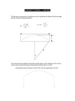
LTE Development Timeline
Ahmed Hamza
Long Term Evolution (LTE) - A Tutorial
October 13, 2009
5 / 48
Introduction
Next Generation Mobile Network (NGMN) Alliance
19 worldwide leading mobile operators
Ahmed Hamza
Long Term Evolution (LTE) - A Tutorial
October 13, 2009
6 / 48
Introduction
LTE Targets
Higher performance
100 Mbit/s peak downlink, 50 Mbit/s peak uplink
1G for LTE Advanced
Faster cell edge performance
Reduced latency (to 10 ms) for better user experience
Scalable bandwidth up to 20 MHz
Backwards compatible
Works with GSM/EDGE/UMTS systems
Utilizes existing 2G and 3G spectrum and new spectrum
Supports hand-over and roaming to existing mobile networks
Reduced capex/opex via simple architecture
reuse of existing sites and multi-vendor sourcing
Wide application
TDD (unpaired) and FDD (paired) spectrum modes
Mobility up to 350kph
Large range of terminals (phones and PCs to cameras)
Ahmed Hamza
Long Term Evolution (LTE) - A Tutorial
October 13, 2009
7 / 48
LTE Architecture
Outline
1
Introduction
2
LTE Architecture
3
LTE Radio Interface
4
Multimedia Broadcast/Multicast Service
5
LTE Deployment Considerations
6
Work Related to Video Streaming
7
Conclusions
Ahmed Hamza
Long Term Evolution (LTE) - A Tutorial
October 13, 2009
8 / 48
LTE Architecture
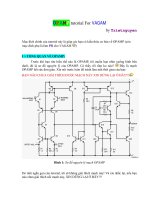
LTE Architecture
LTE encompasses the evolution of:
the radio access through the E-UTRAN
the non-radio aspects under the term System Architecture
Evolution (SAE)
Entire system composed of both LTE and SAE is called the
Evolved Packet System (EPS)
At a high-level, the network is comprised of:
Core Network (CN), called Evolved Packet Core (EPC) in SAE
access network (E-UTRAN)
A bearer is an IP packet flow with a defined QoS between the
gateway and the User Terminal (UE)
CN is responsible for overall control of UE and establishment of
the bearers
Ahmed Hamza
Long Term Evolution (LTE) - A Tutorial
October 13, 2009
9 / 48
LTE Architecture
LTE Architecture
Ahmed Hamza
Long Term Evolution (LTE) - A Tutorial
October 13, 2009
10 / 48
LTE Architecture
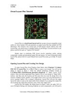
LTE Architecture
Main logical nodes in EPC are:
PDN Gateway (P-GW)
Serving Gateway (S-GW)
Mobility Management Entity (MME)
EPC also includes other nodes and functions, such:
Home Subscriber Server (HSS)
Policy Control and Charging Rules Function (PCRF)
EPS only provides a bearer path of a certain QoS, control of
multimedia applications is provided by the IP Multimedia
Subsystem (IMS), which considered outside of EPS
E-UTRAN solely contains the evolved base stations, called
eNodeB or eNB
Ahmed Hamza
Long Term Evolution (LTE) - A Tutorial
October 13, 2009
11 / 48
LTE Architecture
Ahmed Hamza
Long Term Evolution (LTE) - A Tutorial
October 13, 2009
12 / 48
LTE Radio Interface
Outline
1
Introduction
2
LTE Architecture
3
LTE Radio Interface
4
Multimedia Broadcast/Multicast Service
5
LTE Deployment Considerations
6
Work Related to Video Streaming
7
Conclusions
Ahmed Hamza
Long Term Evolution (LTE) - A Tutorial
October 13, 2009
13 / 48
LTE Radio Interface
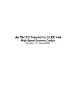
LTE Radio Interface Architecture
eNB and UE have control plane and data plane protocol layers
Data enters
processing chain in
the form of IP
packets on one of
the SAE bearers
Ahmed Hamza
Long Term Evolution (LTE) - A Tutorial
October 13, 2009
14 / 48
LTE Radio Interface
Protocol Layers
IP packets are passed through multiple protocol entities:
Packet Data Convergence Protocol (PDCP)
IP header compression based on Robust Header Compression
(ROHC)
ciphering and integrity protection of transmitted data
Radio Link Control (RLC)
segmentation/concatenation
retransmission handling
in-sequence delivery to higher layers
Medium Access Control (MAC)
handles hybrid-ARQ retransmissions
uplink and downlink scheduling at the eNodeB
Physical Layer (PHY)
coding/decoding
modulation/demodulation (OFDM)
multi-antenna mapping
other typical physical layer functions
Ahmed Hamza
Long Term Evolution (LTE) - A Tutorial
October 13, 2009
15 / 48
LTE Radio Interface
Communication Channels
RLC offers services to PDCP in the form of radio bearers
MAC offers services to RLC in the form of logical channels
PHY offers services to MAC in the form of transport channels
A logical channel is defined by the type of information it carries.
Generally classified as:
a control channel, used for transmission of control and
configuration information necessary for operating an LTE system
a traffic channel, used for the user data
A transport channel is defined by how and
with what characteristics the information is transmitted over the
radio interface
Ahmed Hamza
Long Term Evolution (LTE) - A Tutorial
October 13, 2009
16 / 48
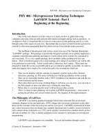
LTE Radio Interface
Channel Mapping
BCCH: Broadcast
DL-SCH: Downlink Shared
CCCH: Common
DTCH: Dedicated Traffic
MCH: Multicast
MTCH: Multicast Traffic
BCH: Broadcast
PCCH: Paging
MCCH: Multicast
PCH: Paging
Ahmed Hamza
DCCH:
Dedicated
Long Term Evolution (LTE) - A Tutorial
October 13, 2009
17 / 48
LTE Radio Interface
Radio Link Control (RLC) Layer
Depending on the scheduler decision, a certain amount of data is
selected for transmission from the RLC SDU buffer and the SDUs
are segmented/concatenated to create the RLC PDU. Thus, for
LTE the RLC PDU size varies dynamically
Each RLC PDU includes a header, containing, among other
things, a sequence number used for in-sequence delivery and by
the retransmission mechanism
A retransmission protocol operates between the RLC entities in
the receiver and transmitter.
Receiver monitors sequence numbers and identifies missing PDUs
Although the RLC is capable of handling transmission errors,
error-free delivery is in most cases handled by the MAC-based
hybrid-ARQ protocol
Ahmed Hamza
Long Term Evolution (LTE) - A Tutorial
October 13, 2009
18 / 48
LTE Radio Interface
Medium Access Control (MAC) Layer
Data on a transport channel is organized into transport blocks.
Each Transmission Time Interval (TTI), at most one transport
block of a certain size is transmitted over the radio interface
to/from a mobile terminal (in absence of spatial multiplexing)
Each transport block has an associated Transport Format (TF)
specifies how the block is to be transmitted over the radio interface
(e.g. transport-block size, modulation scheme, and antenna
mapping)
By varying the transport format, the MAC layer can realize
different data rates.
Rate control is therefore also known as transport-format selection
Ahmed Hamza
Long Term Evolution (LTE) - A Tutorial
October 13, 2009
19 / 48
LTE Radio Interface
Hybrid ARQ (HARQ)
In hybrid ARQ, multiple parallel stop-and-wait processes are used
(this can result in data being delivered from the hybrid-ARQ
mechanism out-of-sequence, in-sequence delivery is ensured by
the RLC layer)
Hybrid ARQ is not applicable for all types of traffic (broadcast
transmissions typically do not rely on hybrid ARQ). Hence, hybrid
ARQ is only supported for the DL-SCH and the UL-SCH
Ahmed Hamza
Long Term Evolution (LTE) - A Tutorial
October 13, 2009
20 / 48
LTE Radio Interface
Physical (PHY) Layer
Based on OFDMA with cyclic prefix in downlink, and on SC-FDMA
with a cyclic prefix in the uplink
Three duplexing modes are supported: full duplex FDD, half
duplex FDD, and TDD
Two frame structure types:
Type-1 shared by both full- and half-duplex FDD
Type-2 applicable to TDD
A radio frame has a length of 10 ms and contains 20 slots (slot
duration is 0.5 ms)
Two adjacent slots constitute a subframe of length 1 ms
Supported modulation schemes are: QPSK, 16QAM, 64QAM
Broadcast channel only uses QPSK
Maximum information block size = 6144 bits
CRC-24 used for error detection
Ahmed Hamza
Long Term Evolution (LTE) - A Tutorial
October 13, 2009
21 / 48
LTE Radio Interface
Type-1 Frame
Ahmed Hamza
Long Term Evolution (LTE) - A Tutorial
October 13, 2009
22 / 48
LTE Radio Interface
Type-2 Frame
Ahmed Hamza
Long Term Evolution (LTE) - A Tutorial
October 13, 2009
23 / 48
LTE Radio Interface
Scheduler in eNB (base station) allocates resource blocks (which
are the smallest elements of resource allocation) to users for
predetermined amount of time
Slots consist of either 6 (for long cyclic prefix) or 7 (for short cyclic
prefix) OFDM symbols
Longer cyclic prefixes are desired to address longer fading
Number of available subcarriers changes depending on
transmission bandwidth (but subcarrier spacing is fixed)
Ahmed Hamza
Long Term Evolution (LTE) - A Tutorial
October 13, 2009
24 / 48
LTE Radio Interface
Downlink Resource Block
Ahmed Hamza
Long Term Evolution (LTE) - A Tutorial
October 13, 2009
25 / 48