Nhà thông minh _smarthouse
Bạn đang xem bản rút gọn của tài liệu. Xem và tải ngay bản đầy đủ của tài liệu tại đây (1.23 MB, 11 trang )
444
EIB EASY
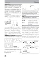
Activate function
at basic unit.
Execute
new function
Execute
new function
Operate
Operate
Operate
Channel on actuator
(e.g. shutter actuator)
which is to be linked.
Channel (rocker) on sensor
(e.g. push-button) which is
to trigger the actuator.
To other sensors which
are to trigger the actuator.
Terminate function
at basic unit.
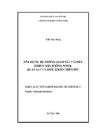
All bus-compatible EIB EASY installation devices, including the
basic unit, sensors and actuators, are connected to the 2-wire bus
cable.
Sensors such as push-buttons, motion sensors and binary inputs
absorb information and transmit it as information via the bus.
Actuators receive the information and put it into action, e.g. trans-
form it into switch, dimmer or blind signals. The bus cable leads to
each EASY bus device. Sensors generally require only the bus
cable. Actuators usually also need the 230/400 V mains supply to
control the users. The bus cable and the mains supply are strictly
separated.
In the case of conventional installation, devices such as switches
and lamps have a fixed allocation in a room due to their connection
to the mains current. The electric circuit runs to the lamp via the
switch and the switch supplies the full power for the lamp. If the
customer wishes this to be altered, the installation has to be rewi-
red.
This is no problem with the EIB EASY system, as switches in this
system do not have a fixed allocation or fixed wiring to certain
lamps. All EIB EASY devices are connected to each other via a 2-
wire bus cable. The bus cable provides the power supply, allowing
information to be exchanged between the Easy devices. The EIB
EASY system is based on the INSTABUS EIB, which was a great
market success. The EIB EASY devices are compatible with the
INSTABUS EIB. They are easier to operate, as no external program-
ming software is required.
The centrepiece of the EIB EASY system is the basic unit. It con-
tains an integrated power supply for generating bus voltage for up
to 64 EIB EASY bus devices. The unit has an 8-gang switching
actuator for switching eight users. With integrated 4-channel timer
and scene function for 4 actuators.
EIB EASY system
Basic unit
Push-button
Switch actuator
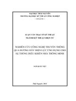
The wiring within the EIB EASY system can be arranged as a linear,
star or tree structure. However, any combinations are also possible.
Linear structure Star structure
Arrangement of the EIB EASY wiring
basic unit
basic unit
Tree structure
basic unit
The following limit values should be observed when laying the bus
cables:
● Max. cable length between basic unit and bus user: 350 m
● Max. cable length between two bus users: 700 m
● Overall length of cables: 1000 m
Device
Device
Device
Device
Basic unit
The EIB EASY devices are connected in parallel via the red/black
bus cable pair using bus supply terminals. Up to four bus cable
pairs (red and black) can be connected to each bus supply terminal.
The bus supply terminal (Art. no. 6897 01) can also be used as a
branching terminal into the terminal sockets of the switch.
Attention should be paid to the correct polarisation during installation
.
In addition to the basic unit, up to 63 more EIB EASY devices can
be connected.
The following types of cables can be used as bus cables:
Type Installation
YCYM Permanent installation:
2 x 2 x 0.8 in dry, damp and wet areas. Surface,
flush-mounted, in pipes. Open, as long as
protected from direct sunlight.
J-Y (St) Y Permanent installation: in dry and damp
2 x 2 x 0.8 workshops, surface, flush-mounted, in
pipes, open, semi-flush-mounted and
flush-mounted.
Cables
Use
After installation is complete and all EIB EASY devices are connec-
ted to the bus, the essential part of the process has been comple-
ted.
By switching on the power supply of the bus on the EIB EASY
basic unit, all the connected EASY devices are ready for use and
are able to communicate with each other. However, they do not yet
know what they actually have to do or with which EASY device
they will carry out their function.
The EIB Easy basic unit recognises the actuators and sensors auto-
matically and puts them into a list for selection. Choose the devi-
ces and device-specific functions which together are to form the
new function. Then give the function a name. The connection infor-
mation is then sent to the actuators and sensors. The project con-
sists of all the functions set up in this manner.
These project data can be saved on the safety card supplied.
As well as being started via the device lists on the basic unit, the
EASY system can also be activated via a simple function allocation
by pressing the buttons on the terminal units.
Simple to operate
IMPORTANT:
Avoid earth loops!
EIB EASY
445
55
Switch actuator functions:
Switching
EASY basic unit REG-K
7900 29
Switch outputs: AC 230 V, 10 A
max. 21 µF
EASY switch actuator flush-mounted UP/230/16
7640 99
Switch output: AC 230 V, 16 A
max. 140 µF
Integrating devices into the functions or removing them is just as
easy as creating new ones. In this way, individual/group or central
functions can be created and allocated to the desired sensor chan-
nels.
These functions can be controlled easily and the function parame-
ters, e.g. times, set via the large display and the buttons on the
basic unit.
The EIB EASY basic unit also works as an 8-gang switching actua-
tor. Eight switch channels are immediately available via manual
operation. Allocating the function is clear and simple due to the
buttons on the basic unit itself.
Function
Design cover
Movement detectors
Detection of movement and triggering of an actua-
tor with timer function, disconnectable movement
detection, light-dependent movement detection,
block function, cycle time, brightness analysis.
Detection of movement and triggering of an actua-
tor with timer function, disconnectable movement
detection, light-dependent movement detection,
block function, cycle time, brightness analysis.
Movement detector/switch actuator
Movement detector functions:
Detection of movement and triggering of an actua-
tor with timer function, disconnectable movement
detection, light-dependent movement detection,
block function, cycle time, brightness analysis.
Switch actuator functions:
Dimming, switching, timer switch
(staircase lighting timer), load management
EASY ARGUS 180 flush-
mounted insert System Basis
7604 19
■
■■
EASY flush-mounted module
for ARGUS 180
7670 04
EASY switch actuator for ARGUS
180 flush-mounted/230/10
7641 94
Switch output: AC 230 V, 10 A
max. 140 µF
EIB EASY movement detectors
Switch actuator
Switch actuator functions:
Switch, timer switch (staircase lighting timer), prewarning function, load management
EASY switch actuator REG-K/8x230/10
7771 08
Switch output: AC 230 V, 10 A
max. 21 µF
EASY shutter actuator
REG-K/4x(1x230)/6
7772 04
Outputs: AC 230 V, 6 A
Shutter actuator
Shutter actuator functions:
Shutters up/down, safety (wind monitoring)
EASY dimmer actuator REG-K/300 W
7777 01
Output: AC 230 V, max. 300 W
Dimmer actuator
Dimmer actuator functions:
Dimming, switching, timer switch (staircase lighting timer), load management
Function EIB EASY devices
EASY dimmer actuator REG-K/400 W
7777 02
Output: AC 230 V, max. 400 W
Dimmer actuator functions:
Dimming, switching, timer switch (staircase lighting timer), load management
The integrated four-channel timer is also available. Additional
devices are not required. The timing can be seen on the LCD.
The scene function for four actuator groups is also included. It
offers the user the option of adapting the unit to suit his personal
requirements.
The functions and EASY devices available are listed in the follo-
wing:
ARGUS 180 flush-mounted
6243...
6214...
6215...
System M
System Design
OCTOCOLOR
Inserts
Blanking cover
6621...
6622...
6620...
Basic unit
Switch actuator functions for 8 channels:
Switch, timer switch (staircase lighting timer), load management
Time switch:
Switching, shutter, release
Scene:
Dimming
446
EIB EASY
Design cover
Function
Tactile sensors
Push-button functions:
Switching, timer switching, dimming, shutter,
scene, load management
Push-button functions:
Switching, timer switching, dimming, shutter,
scene, load management
Push-button functions:
Switching, timer switching, dimming, shutter,
scene, load management
Push-button functions:
Switching, timer switching, dimming, shutter,
scene, load management
Push-button functions:
Switching, timer switching, dimming, shutter,
scene, load management
Push-button functions:
Switching, timer switching, dimming, shutter,
scene, load management
Push-button functions:
Switching, timer switching, dimming, shutter,
scene, load management, IR channels
Tactile sensor/switch actuator
Push-button functions:
Switching, timer switching, dimming, shutter,
scene, load management
Switch actuator functions:
Switching
Push-button functions:
Switching, timer switching, dimming, shutter,
scene, load management
Switch actuator functions:
Switching
Push-button functions:
Switching, timer switching, dimming, shutter,
scene, load management
Switch actuator functions:
Switching
Tactile sensor/shutter actuator
Push-button functions:
Switching, dimming, shutter
Shutter functions:
Shutter up/down, slat adjustment, safety
(wind monitoring)
Push-button functions:
Switching, dimming, shutter
Shutter functions:
Shutter up/down, slat adjustment, safety
(wind monitoring)
Push-button functions:
Switching, dimming, shutter
Shutter functions:
Shutter up/down, slat adjustment, safety
(wind monitoring)
Easy flush-mounted module for
push-button, 1-gang
7670 01
■
■
■
Easy push-button insert, 1-gang
7601 91
Easy flush-mounted module for
push-button, 2-gang
7670 02
Easy push-button insert, 2-gang
7601 92
Easy flush-mounted module for
push-button, 4-gang
7670 03
Easy push-button insert, 4-gang
7601 93
Easy flush-mounted module for
multi-function push-button with IR
7670 05
Easy switch actuator for push-button,
1-gang UP/230/10 (flush-mounted)
7641 91
Switch output: AC 230 V, 10 A
max. 140 µF
Easy switch actuator for push-button,
2-gang UP/230/10 (flush-mounted)
7641 92
switch output: AC 230 V, 10 A
max. 140 µF
Easy switch actuator for push-button,
4-gang UP/230/10 (flush-mounted)
7641 93
Switch output: AC 230 V, 10 A
max. 140 µF
Easy shutter actuator for
push-button, 1-gang UP/230/6
(flush-mounted)
7642 91
Blind output: AC 230 V, 6 A
Easy shutter actuator for
push-button, 2-gang UP/230/6
(flush-mounted)
7642 92
Blind output: AC 230 V, 6 A
Easy shutter actuator for
push-button, 4-gang UP/230/6
(flush-mounted)
7642 93
Blind output: AC 230 V, 6 A
Push-button, 1-gang
6233...
6223...
without status 6201...
with status 6204...
Push-button, 2-gang
6234...
6224...
without status 6202...
with status 6205...
■
■
■
System M
System Design
System Basis
OCTOCOLOR
Inserts
EIB EASY
447
55
■
■
■
■
■
■
■
Push-button, 4-gang
System M 6238...
System Design 6226...
System Basis
OCTOCOLOR without status
6203...
OCTOCOLOR with status
6206...
Multi-function push-button
four-gang with IR receiver
6228...
Rocker for push-button insert
one-gang
6211...
Rocker for push-button insert
two-gang
6212...
Rocker for push-button insert
four-gang
6213...
448
INSTABUS EIB
Sensors and actuators are selected in accordance with the specific
application and comprise a bus coupler and application module
with the corresponding application program. The application pro-
grams are part of the Merten product database and are loaded into
the devices with the ETS planning and start-up software via the
serial port of a PC and via the bus.
INSTABUS EIB is a decentralised bus system. Every INSTABUS
device has its own micro-controller. Devices can exchange data
directly in series via the bus, i.e. without communicating via the
control centre. All devices are bus devices with equal rights (multi-
master operation). The CSMA/CA procedure is used to avoid tele-
gram collisions and loss of data.
INSTABUS EIB is operated with safety extra-low voltage (SELV).
The bus voltage is 24 V DC (+6/–4 V). Bus devices disconnect from
the bus when the voltage drops below 20 V. Data is transmitted at
a speed of 9.6 kbit/s, thus making terminating resistors un-
necessary.
Actuators
Sensors
INSTABUS EIB comprises a two-wire bus line and the connected
bus-compatible installation devices, such as sensors, actuators and
system components.
Sensors record information and then send it to the bus as data
telegrams. Sensors include INSTABUS push-buttons and binary
inputs for connecting floating contacts.
Actuators receive the data telegrams and convert these into
switching or dimming signals, for example.
System devices and components are required for the fundamental
system functions. These are essentially power supplies for genera-
ting the bus voltage, couplers for connecting bus section and inter-
faces for connecting programming devices.
The two-wire bus line carries the power for the electronics of the
bus devices and also the data. The bus line is connected to every
bus device. Sensors normally only use the bus line, while actuators
normally also use the 230/400 V mains supply to control the users.
The bus line and mains supply are strictly separated from one
another.
INSTABUS EIB system features
INSTABUS EIB is subdivided into hierarchically structured sections.
The line represents the smallest unit and comprises up to 64 bus
devices (TLN) as well as a power supply with choke (SV). Up to 15
lines can be interconnected via line couplers (LK) which are in turn
connected via a main line to create an area. In larger installations, up
to 15 areas can in turn be connected via area couplers (BK) and an
area line. The main and area lines also require a power supply with
choke.
Over 12,000 bus devices can be connected to INSTABUS when all
lines and areas are used.
INSTABUS EIB topology
The routing within a line can be linear, start-shaped or tree-shaped,
or any combination thereof.
Linear structure
INSTABUS routing
+
-
0
l
6
5
3
2
*
Merten
Star-structure
0
l
6
5
3
2
*
Merten
+
-
Tree-structure
0
l
6
5
3
2
*
Merten
+
-
ll
OO
The following limits must be observed when installing the bus
lines:
● Max. cable length between power supply and bus device: 350 m
● Max. cable length between two bus devices: 700 m
● Overall length of cables within a line: 1000 m