Chapter 4 Datums
Bạn đang xem bản rút gọn của tài liệu. Xem và tải ngay bản đầy đủ của tài liệu tại đây (1.42 MB, 56 trang )
Chapter
4
Datums
After completing this chapter you will be able to:
• Understand the three default datum planes.
• Create the datum planes using different constraints available.
• Create datums on the fly.
• Create datum axes using the different constraints available.
• Create the datum points.
• Create extrude and revolve cuts.
Learning Objectives
4-2 Pro/ENGINEER for Designers
© CADCIM T© CADCIM T
© CADCIM T© CADCIM T
© CADCIM T
echnologies, USAechnologies, USA
echnologies, USAechnologies, USA
echnologies, USA
. F. F
. F. F
. F
or online training, contact online training, contact
or online training, contact online training, contact
or online training, contact
DATUMS
Datums are imaginary features with no mass or volume and are available to help you in creating
a model, they act as reference for sketching of a feature, orientation of a model, assembling
components, and so on. Remember that the datums play a very important role in
creating complex models in Pro/ENGINEER and therefore you must have a good understanding
of datums. Datums are considered to be features but not model geometry. In Pro/ENGINEER,
datums exist as datum plane, datum curve, datum point, datum coordinate system, datum
graph, and so on.
Default Datum Planes
When you enter the Part mode or the Assembly mode, the three datum planes are by
default displayed on the graphics screen. These datum planes are mutually perpendicular to
each other. These are known as the default datum planes. The only difference between the
default datum planes of the Part mode and those of the Assembly mode lies in the names of
the datum planes.
The default datum planes in the Part mode are named as FRONT, TOP, and RIGHT. In case
of Assembly mode, the default datum planes are named as ASM_FRONT, ASM_TOP, and
ASM_RIGHT. However, the names of the default datum planes can be changed as required.
To change the names, choose PART > Set Up > Name. You will be prompted to select a
feature to change the name. Select the datum plane you want to rename. When the Message
Input Window appears, enter the desired name in this window.
There are two sides of a datum plane, colored yellow and red. Generally, the protrusion takes
place toward the yellow side of the datum plane and the cut takes place towards the red side.
This is the reason, while extruding a section, by default, the red arrow always points out of the
screen. You can change the colors of the datum planes according to your convenience. The
colors of the datum planes help in identifying the direction of feature orientation.
NEED FOR DATUMS IN MODELING
Generally, most of the engineering components or designs consist of more than one feature.
First the base feature of the model is created and then the other features of the model are
created. Since all the features of a model cannot be drawn on a single plane, therefore, to draw
the rest of the features sometimes additional planes have to be created or selected. Also, most
of the times the three default datum planes are not enough to create a complex model having
many features. For example, Figure 4-1 shows a simple model that consists of two features that
require two different planes.
In Figure 4-1 any of the two features that are defined on two different planes can be considered
as the base feature. However, in this discussion the base feature that is decided to be created is
Tip: Whenever you come across any solid model, first try to visualize the number of
features in that model and then decide which feature in the model you consider as the
base feature.
Datums 4-3
© CADCIM T© CADCIM T
© CADCIM T© CADCIM T
© CADCIM T
echnologies, USAechnologies, USA
echnologies, USAechnologies, USA
echnologies, USA
. F. F
. F. F
. F
or engineering seror engineering ser
or engineering seror engineering ser
or engineering ser
vices, contact , contact
vices, contact , contact
vices, contact
shown in Figure 4-2. After creating the base feature, the next feature has to be created. For the
next feature, a sketching plane has to be defined. Therefore, an additional plane will be created
on which you can draw the sketch for the second feature.
As shown in Figure 4-3, the plane that is used for the creation of the base feature is highlighted
by a mesh. To create the second feature, a new plane is created that is shown in Figure 4-4. The
sketch of the second feature is drawn on this plane and this is the reason, the front planar
surface is coplanar with the datum plane.
DATUM OPTIONS
After discussing the default datum planes that are the first feature in the Part mode, you must
know the different features created using the datum options. Datums are also considered as
features that have no geometry. Figure 4-5 shows the Datum toolbar. Figure 4-6 shows the
method of invoking different types of datum features from the menu bar.
Figure 4-2 Base feature of the modelFigure 4-1 Model having two extruded features
Figure 4-4 Plane selected for the second feature
Figure 4-3 Plane selected for the base feature
4-4 Pro/ENGINEER for Designers
© CADCIM T© CADCIM T
© CADCIM T© CADCIM T
© CADCIM T
echnologies, USAechnologies, USA
echnologies, USAechnologies, USA
echnologies, USA
. F. F
. F. F
. F
or online training, contact online training, contact
or online training, contact online training, contact
or online training, contact
Datum Planes
We can create datum planes other than the three default datum planes using the menu bar or
the Datum toolbar. The datum planes can be created at anytime when required. The display of
the datum planes can be turned on or off by using the Datum planes on/off button from the
Datum Display toolbar. Before discussing the procedure to create the datum planes using the
different options, it is important for you to understand the use of datum planes. Some of the
uses of datum planes are listed below:
1. Datum planes are used as sketching planes to create sketches for the different features of
a model.
2. Datum planes are used as reference planes for sketching.
3. Datum planes are used as references for placing holes and for assembly.
4. Datum planes are used as a reference for mirroring features, copying features, for creating
a cross-section, and as well as for orientation of references.
Figure 4-6 Invoking the datum options from the Insert
menu in the menu bar
Figure 4-5 Datum toolbar
Datums 4-5
© CADCIM T© CADCIM T
© CADCIM T© CADCIM T
© CADCIM T
echnologies, USAechnologies, USA
echnologies, USAechnologies, USA
echnologies, USA
. F. F
. F. F
. F
or engineering seror engineering ser
or engineering seror engineering ser
or engineering ser
vices, contact , contact
vices, contact , contact
vices, contact
Pro/ENGINEER provides you with different options to create datum planes other than the
default datum planes. With this release of Pro/ENGINEER, datums can even be created while
you are in the sketcher environment. When you choose Insert > Datum > Plane from the
menu bar or Insert a datum plane. button from the Datum toolbar, the DATUM PLANE
submenu appears with the different options to create datum planes. Similarly, separate buttons
for creating datum axis, datum curve, datum point, datum coordinate system, and so on are
available in the Datum toolbar.
Figure 4-7 shows the different options available in the DATUM PLANE
submenu to create datum planes. Some of the options are standalone
and some require more than one constraint to define a datum plane,
that is, they are applied in pairs. The standalone options are constraints
that are sufficient by themselves to constrain a datum plane definition.
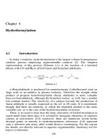
Through Option
The Through option is used to create a datum plane through any
specified axis, edge, curve, point/vertex, plane, cylinder, or coordinate
system. This option can be used in combination with other different
sub-options that are available in the DATUM PLANE submenu.
However, the combinations of options that you can use as standalone
are Through > AxisEdgeCurv, Through > Plane, and Through >
Cylinder. Figure 4-8 shows the datum plane constraint combinations
using the Through option. Datum planes can be created using any of
the combinations shown in the figure. The possible combinations of
datum plane creation are referred to as Ye s and the combinations that
are not possible are referred to as No in the figure.
While reading the table shown in Figure 4-8, first preference is given
to the text written in first column and then the text in the first row
should be read. For example, if you want to make a datum plane that is passing through a
cylinder and normal to a plane then look for Through in the first column and then for Cylinder
in second column. Now, look for Normal in the first row and for Plane in the second row. After
finding both the combination trace them in the respective column and row till they intersect.
You will find Ye s. This suggests that the creation of a datum plane that passes through a
cylinder and is normal to a plane is possible. While reading the table shown in Figure 4-8,
remember that the constraints that are not standalone have to be applied in pairs. When the
constraint applied is sufficient to constrain a datum plane, the message, Datum Plane is fully
constrained. Select "Done", "Quit" or "Restart" is displayed in the Message Area.
Figure 4-9 shows that the cylindrical surface and the default datum planes are used to create a
datum plane at an angle to the selected default datum plane and passing through the center
of the cylindrical surface as shown in Figure 4-10.
Figure 4-7 DATUM
PLANE submenu
Tip: Generally, for the base feature creation, the three default datum planes are used
and as the part becomes complex or in other words as the number of features increases,
the need for additional datum planes arises.
4-6 Pro/ENGINEER for Designers
© CADCIM T© CADCIM T
© CADCIM T© CADCIM T
© CADCIM T
echnologies, USAechnologies, USA
echnologies, USAechnologies, USA
echnologies, USA
. F. F
. F. F
. F
or online training, contact online training, contact
or online training, contact online training, contact
or online training, contact
Figure 4-10 Resultant datum plane passing
through the center of a cylinder and at an angle
Figure 4-9 Selecting a cylindrical surface and a
default datum plane to create a datum plane
Figure 4-8 Datum plane constraint combinations using the Through option
Normal Option
The Normal option is used to create a datum plane normal to any specified axis, edge, curve,
or plane. This option is used in combination with other different sub-options that are available
in the DATUM PLANE submenu. The Normal option in combination with any of the
sub-options cannot be used as standalone. Figure 4-11 shows the datum plane constraint
combinations using the Normal option. The possible combinations of datum plane creation
are referred to as Yes and the combinations that are not possible are referred to as No.
Datums 4-7
© CADCIM T© CADCIM T
© CADCIM T© CADCIM T
© CADCIM T
echnologies, USAechnologies, USA
echnologies, USAechnologies, USA
echnologies, USA
. F. F
. F. F
. F
or engineering seror engineering ser
or engineering seror engineering ser
or engineering ser
vices, contact , contact
vices, contact , contact
vices, contact
Figure 4-12 shows a planar surface and a cylindrical surface. The planar surface is selected as
the normal surface and the cylindrical surface is selected to be tangent to the datum plane.
The datum plane that is created is shown Figure 4-13.
Parallel Option
The Parallel option is used to create a datum plane parallel to any specified datum plane or
planar surface. This option is used in combination with other different sub-options in the
DATUM PLANE submenu. The Parallel option in combination with the Plane sub-option
cannot be used as standalone. Figure 4-14 shows different datum plane constraint combinations
using the Parallel option. The possible combinations of datum plane creation are referred to
as Yes and the combinations that are not possible are referred to as No in the figure.
Figure 4-11 Datum plane constraints combinations using the Normal option
Figure 4-13 Resultant datum planeFigure 4-12 Selecting a planar surface and a
cylindrical surface to create a datum plane
4-8 Pro/ENGINEER for Designers
© CADCIM T© CADCIM T
© CADCIM T© CADCIM T
© CADCIM T
echnologies, USAechnologies, USA
echnologies, USAechnologies, USA
echnologies, USA
. F. F
. F. F
. F
or online training, contact online training, contact
or online training, contact online training, contact
or online training, contact
Figure 4-16 Resultant datum plane
Figure 4-15 Selecting a datum plane and an axis
to create a datum plane
Figure 4-15 shows the selection of a default datum plane and an axis to create a datum plane.
The resultant datum plane is parallel to the selected datum plane and passes through the axis
as shown in Figure 4-16.
Offset Option
The Offset option is used to create a datum plane at an offset distance to any specified plane
or coordinate system. This option is used in combination with other different sub-options
available in this submenu. However, the Offset > Plane option can be used as standalone.
This option is used to create a datum plane at some specified parameters. The parameters
that are required to specify the offset distance are discussed below:
Thru Point
The Thru Point option is used to specify a point on the model through which the datum
plane will pass.
Figure 4-14 Datum plane constraint combinations using the Parallel option
Datums 4-9
© CADCIM T© CADCIM T
© CADCIM T© CADCIM T
© CADCIM T
echnologies, USAechnologies, USA
echnologies, USAechnologies, USA
echnologies, USA
. F. F
. F. F
. F
or engineering seror engineering ser
or engineering seror engineering ser
or engineering ser
vices, contact , contact
vices, contact , contact
vices, contact
Figure 4-17 Datum plane constraint combinations using the Offset option
Enter Value
The Enter Value option is used to specify an offset distance and in the case of angular
planes you have to specify the angle. These values are entered in the Message Input
Window that appears. An arrow appears on the model that shows the positive direction of
the offset distance or angle.
Figure 4-17 shows different datum plane constraint combinations using the Offset option.
The possible combinations of datum plane creation are referred to as Yes and the combinations
that are not possible are referred to as No in the figure.
Figure 4-18 shows the selection of a default datum plane and a vertex to define an offset
datum plane. The resultant datum plane is at an offset to the selected datum plane and passes
through the vertex as shown in Figure 4-19.
Figure 4-19 Resultant datum planeFigure 4-18 Selecting a datum plane and an axis
to create a datum plane
4-10 Pro/ENGINEER for Designers
© CADCIM T© CADCIM T
© CADCIM T© CADCIM T
© CADCIM T
echnologies, USAechnologies, USA
echnologies, USAechnologies, USA
echnologies, USA
. F. F
. F. F
. F
or online training, contact online training, contact
or online training, contact online training, contact
or online training, contact
Angle Option
The Angle option is used to create datum planes through any specified plane. This option is
used with other sub-options in the DATUM PLANE submenu to create different types of
datum planes. The Angle > Plane combination of options cannot be used as standalone. The
value for angle is entered in the Message Input Window that appears when all the constraints
are defined. Figure 4-20 shows the datum plane constraint combinations using the Angle
option. The possible combinations of datum plane creation are referred to as Ye s and the
combinations that are not possible are referred to as No in the figure.
Figure 4-21 shows the selection of a planar surface, an edge and a vertex to create a datum
plane that is shown in Figure 4-22. The datum plane created is at an angle to the selected
planar surface and passes through the selected edge and vertex. The vertex is selected by
choosing the Thru Point option from the OFFSET submenu that is displayed when you choose
Done from the DATUM PLANE submenu.
Figure 4-20 Datum plane constraint combinations using the Angle option
Figure 4-22 Resultant datum plane
Figure 4-21 Selecting a datum plane and an axis
to create a datum plane
Datums 4-11
© CADCIM T© CADCIM T
© CADCIM T© CADCIM T
© CADCIM T
echnologies, USAechnologies, USA
echnologies, USAechnologies, USA
echnologies, USA
. F. F
. F. F
. F
or engineering seror engineering ser
or engineering seror engineering ser
or engineering ser
vices, contact , contact
vices, contact , contact
vices, contact
Tangent Option
The Tangent option creates datum planes tangent to cylindrical features. This option is also
used with the other options in the DATUM PLANE submenu to create different types of
datum planes. Figure 4-23 shows the datum plane constraint combinations using the Tangent
option. The possible combinations of datum plane creation are referred to as Ye s and the
combinations that are not possible are referred to as No in the figure.
BlendSection Option
The BlendSection option is used to create the datum planes by selecting the features. This
option works as standalone.
Datum Planes Created “On The Fly”
The term “On the Fly” refers to the creation of a datum plane when the system prompts you
to select or create a plane. At this step, the SETUP PLANE submenu is displayed. When you
choose the Make Datum option from this submenu, the DATUM PLANE submenu is displayed.
You can select the options from this submenu to create a datum plane. When you create a
datum plane using the Make Datum option, the datum plane is neither visible on the graphics
screen nor is displayed on the Model Tree once the feature is completed. This option of
creating datum planes is referred to as “creating datum planes on the fly”. This option is
provided by Pro/ENGINEER in order to avoid cluttering of datum planes in a complex model.
Datum Axes
Datum axis is an imaginary axis that is created in Pro/ENGINEER to help you in creating a
model. Datum axes can be created manually. They are also created automatically when any
cylindrical feature is created. The display of a datum axis can be turned on or off by using the
Datum axes on/off button from the Datum Display toolbar. The uses of datum axes are discussed
next:
1. Datum axes act as reference for feature creation.
Figure 4-23 Datum plane constraints combination using the Tangent option
4-12 Pro/ENGINEER for Designers
© CADCIM T© CADCIM T
© CADCIM T© CADCIM T
© CADCIM T
echnologies, USAechnologies, USA
echnologies, USAechnologies, USA
echnologies, USA
. F. F
. F. F
. F
or online training, contact online training, contact
or online training, contact online training, contact
or online training, contact
2. They are used in creating a datum plane along with different constraint combinations.
3. They are used in placing features co-axially.
4. They are also used to create radial patterns. You will learn to create patterns in Chapter 6.
Datum axes are named by default in Pro/ENGINEER. The default
name of a datum axis is A_(Number), where Number represents
the number of that datum axis. However, the default name of the
datum axes can be changed in the same way as that of the datum
planes.
When you choose Insert > Datum > Axis from the menu bar or
Insert a datum axis. button from the Datum toolbar, the DATUM
AXIS submenu appears with different options to create datum axes
as shown in Figure 4-24. The options in the DATUM AXIS submenu
are explained next. These options are explained using an extruded
model.
Thru Edge Option
The Thru Edge option is used to create a datum axis through any selected edge. The selected
edge must be straight for the creation of a datum axis. In Figure 4-25, A_1 is the datum axis
created using this option.
Note
Unlike the datum planes constraint options, all the datum axes constraint options are standalone.
While creating a datum axis, some options in the DATUM AXIS submenu require datum points
to be selected while constraining the datum axis. Therefore, while using options like Pnt Norm
Pln and Pnt on Surf from the DATUM AXIS submenu, you need to create datum points.
Normal Pln Option
The Normal Pln option is used to create a datum axis normal to any selected planar surface or
datum plane. When you select a planar surface or a datum plane, you are prompted to select
its placement location on the datum plane. After you select its placement location, you are
prompted to select two edges, axes, datums, or planar surfaces to specify the linear dimension
for the placement of the datum axis. When you select the first edge for the placement dimensions
of the axis, the Message Input Window is displayed. A default value is displayed in the window.
You can accept the default dimension or change it to the required value. Similarly, select the
second edge for dimensioning and enter the dimension value in the window that appears. In
Figure 4-26, A_2 is the datum axis created using this option.
Pnt Norm Pln Option
The Pnt Norm Pln option creates a datum axis passing through a datum point and normal to
any planar surface or datum plane. When you choose this option to create a datum axis, you
Figure 4-24 DATUM
AXIS submenu
Datums 4-13
© CADCIM T© CADCIM T
© CADCIM T© CADCIM T
© CADCIM T
echnologies, USAechnologies, USA
echnologies, USAechnologies, USA
echnologies, USA
. F. F
. F. F
. F
or engineering seror engineering ser
or engineering seror engineering ser
or engineering ser
vices, contact , contact
vices, contact , contact
vices, contact
are prompted to select a datum plane or a planar surface. Select a plane to which the datum
axis will be normal. Now, you are prompted to select a datum point. Select a datum point to
create an axis passing through the datum point. In Figure 4-27, A_3 is the datum axis created
using this option.
Thru Cyl Option
The Thru Cyl option is used to create a datum axis through a cylindrical or a round surface.
When you choose this option from the DATUM AXIS submenu, you are prompted to select a
revolved surface. The axis is automatically created around the revolved surface through an
imaginary axis. In Figure 4-28, A_4 is the datum axis that is created using this option.
Figure 4-26 Datum axis created normal to
the plane
Figure 4-25 Datum axis created along the edge
Figure 4-28 Datum axis passing through a
cylinder
Figure 4-27 Datum axis passing through the
datum point and normal to the plane
4-14 Pro/ENGINEER for Designers
© CADCIM T© CADCIM T
© CADCIM T© CADCIM T
© CADCIM T
echnologies, USAechnologies, USA
echnologies, USAechnologies, USA
echnologies, USA
. F. F
. F. F
. F
or online training, contact online training, contact
or online training, contact online training, contact
or online training, contact
Two Planes Option
The Two Planes option is used to create a datum axis passing through the edge where two
planes meet or at the intersection edge of two planar surfaces or datum planes. When you
choose this option, you are prompted to select a planar surface or a datum plane. In Figure 4-29,
A_5 is the datum axis that is created using this option.
Two Pnt/Vtx Option
The Two Pnt/Vtx option is used to create a datum axis between two datum points or edge
vertices. When you choose this option, you are prompted to select datum points or edge
vertices. The datum axis is created along the two selected datum points or edge vertices. In
Figure 4-30, A_6 is the datum axis that is created using this option.
Pnt on Surf Option
The Pnt on Surf option is used to create a datum axis passing through any selected datum
point on a surface. When you choose this option, you are prompted to select a placement
point. The datum axis is created normal to the surface on which the datum point is selected
and passes through the datum point. In Figure 4-31, A_7 is the datum axis that is created
using this option.
Tan Curve Option
The Tan Curve option creates a datum axis tangent to a curve and passing through one of its
vertex. When you choose this option, you are prompted to select an edge or a curve. After you
select a curve or an edge you are prompted to select one vertex of the edge. The datum axis is
created tangent to the curve and passes through its selected vertex. In Figure 4-32, A_8 is the
datum axis that is created using this option.
Datum Points
Datum points are imaginary points created in Pro/ENGINEER to aid in creating models,
drawings, analyzing models, and so on. The uses of datum points are discussed next.
Figure 4-30 Datum axis created between the
two selected vertices
Figure 4-29 Datum axis created on the edge
where the two selected planes meet
Datums 4-15
© CADCIM T© CADCIM T
© CADCIM T© CADCIM T
© CADCIM T
echnologies, USAechnologies, USA
echnologies, USAechnologies, USA
echnologies, USA
. F. F
. F. F
. F
or engineering seror engineering ser
or engineering seror engineering ser
or engineering ser
vices, contact , contact
vices, contact , contact
vices, contact
1. To create datum planes and axes.
2. To associate note in the drawings and attach datum targets.
3. To create coordinate system.
4. To specify point loads for mesh generation.
5. To create pipe features.
The default name associated with a datum point by Pro/ENGINEER is PTN(Number) where
Number indicates the number of datum points created in a particular object. However, you
can change the default name associated with the datum points.
When you choose Insert > Datum > Point from the menu bar or
Insert a datum point. button from the Datum toolbar, the DATUM
POINT submenu appears with different options to create datum
points as shown in Figure 4-33. The options in the DATUM POINT
submenu are explained next.
On Surface Option
The On Surface option is used to create datum points on a planar
surface. When you choose this option from the DATUM POINT
submenu, you are prompted to select the desired location for the
placement of the datum point. When you select a planar surface or
a datum plane to place the datum point, a red colored point is
displayed at the selected point on the surface. Confirm the selection
using the middle mouse button. Next, you are prompted to select
Figure 4-32 Datum axis created tangent to the
selected curve
Figure 4-31 Datum axis passing through the
datum point
Figure 4-33 DATUM
POINT submenu
4-16 Pro/ENGINEER for Designers
© CADCIM T© CADCIM T
© CADCIM T© CADCIM T
© CADCIM T
echnologies, USAechnologies, USA
echnologies, USAechnologies, USA
echnologies, USA
. F. F
. F. F
. F
or online training, contact online training, contact
or online training, contact online training, contact
or online training, contact
two planes or edges to specify the linear dimensions for the placement of the datum point.
After you select the two planes or edges for the placement dimension of the point, the Message
Input Window is displayed with the first selection highlighted and you are prompted to specify
the distance from the highlighted references. A default value is displayed in the window. You
can accept the default value or change it to the required value and then press ENTER. The
second selection will be highlighted and you will be prompted to enter the distance from the
highlighted references. Enter the dimension value in the window that appears. Press the middle
mouse button, the datum point is created.
Offset Surf Option
The Offset Surf option creates datum points at an offset distance from a specified planar
surface or a datum plane in a specified direction. When you choose this option to create a
datum point, you are prompted to select the desired location for the datum point. Select a
planar surface or a datum plane from where the offset distance for the placement of the datum
point will be measured. Use the middle mouse button to confirm the selection. You will be
prompted to select the planes or the edges for dimensioning the point. Select two planes or
edges for dimensioning and enter the distances from the highlighted references. You will now
be prompted to enter the offset distance in the specified direction shown by the arrow. Enter
the value in the Message Input Window that appears and press ENTER. Press the middle
mouse button and the datum point is created. If you enter a negative value in the Message
Input Window then the datum point will be created in the direction opposite to that shown by
the arrow.
Curve X Srf Option
The Curve X Srf option is used to create a datum point at the intersection of a curve and a
surface. When you choose this option to create a datum point, you will be prompted to select
a curve, edge, or axis. After selecting the curve, edge, or axis, you are prompted to select
surfaces that intersect the edge. Select a surface or a datum plane. Press the middle mouse
button and the datum point is created.
On Vertex Option
The On Vertex option is used to create a datum point on the vertex of a part, edge, surface
feature edge, or a datum curve. When you choose this option, you are prompted to select
vertices where you want to place the datum points. Select the vertices and press the middle
mouse button to create the datum points.
Offset Csys Option
The Offset Csys option is used to create an array of datum points at an offset distance from
a coordinate system. You can change the array of the points by redefining the array.
When you choose this option, you are prompted to select a coordinate system. After selecting
a coordinate system, the SET CSYS TYP (Set Coordinate System Type) submenu is displayed
and you are prompted to select the type of coordinate system; Cartesian, Cylindrical, or
Spherical. After selecting the type of coordinate system, the POINT ARRAY submenu is
displayed and you are prompted to enter the points. Choose the Enter Points option from the
Datums 4-17
© CADCIM T© CADCIM T
© CADCIM T© CADCIM T
© CADCIM T
echnologies, USAechnologies, USA
echnologies, USAechnologies, USA
echnologies, USA
. F. F
. F. F
. F
or engineering seror engineering ser
or engineering seror engineering ser
or engineering ser
vices, contact , contact
vices, contact , contact
vices, contact
POINT ARRAY submenu. The Message Input Window is displayed and you are prompted
to enter a parameter, this parameter will define the location of the datum point and depends
on the type of coordinate system selected from the SET CSYS TYP submenu.
Three Srfs Option
The Three Srfs option is used to create datum points at the intersection of three surfaces.
When you choose this option, you are prompted to select the first surface. After selecting the
first surface, you are prompted to select the second surface. Select the second surface. You will
then be prompted to select the third surface. Select the third surface on the model. The datum
point is placed at the intersection of the three surfaces selected and appears in green color.
Confirm the selection by using the middle mouse button. Using this option, you can also
select datum planes to create datum points.
At Center Option
The At Center option creates a datum point at the center of an arc or a circle. When you
choose this option, you are prompted to select an edge or a curve, at the center of which the
datum point will be created. Confirm the selection by using the middle mouse button. The
datum point will be created.
On Curve Option
The On Curve option is used to create a datum point on an edge or a curve. When you choose
this option, the DTM PNT MODE submenu and the PNT DIM MODE submenu are displayed
and you are prompted to specify the dimension type for the datum point. Choose the options
from the PNT DIM MODE submenu to select the type of dimensioning.
Crv X Crv Option
The Crv X Crv option is used to create a datum point on a datum curve at the point that is at
the minimum distance from another datum curve.
When you choose this option, you are prompted to select a curve where the point should be
placed. After selecting the datum curve, you are prompted to select a second curve close to the
placement of the point. The datum point will be created on the first curve at a point that is
closest to the second curve.
Note
Datum curves will be discussed in Chapter 7.
Offset Point Option
The Offset Point option is used to create datum points at an offset
distance from a point or a vertex. When you choose the Offset Point
option from the DATUM POINT submenu, the OFFSET DIR
submenu is displayed as shown in Figure 4-34. The options in this
submenu are discussed next.
Figure 4-34 OFFSET
DIR submenu
4-18 Pro/ENGINEER for Designers
© CADCIM T© CADCIM T
© CADCIM T© CADCIM T
© CADCIM T
echnologies, USAechnologies, USA
echnologies, USAechnologies, USA
echnologies, USA
. F. F
. F. F
. F
or online training, contact online training, contact
or online training, contact online training, contact
or online training, contact
Figure 4-35 FIELD
PNT submenu
Entity/Edge
When you choose the Entity/Edge option, you are prompted to select an axis, a straight
edge, or a straight curve. After you select any one of the above mentioned entities, you are
prompted to select vertices, points, or coordinate systems to offset from. After selecting a
vertex, a point, or a coordinate system, press the middle mouse button. The Message
Input Window is displayed and you are prompted to specify the offset distance in the
direction shown by the red arrow. The datum point will be placed at the specified distance
from the selected entity. In case you want to create more then one datum points, you need
to select more then one vertices, points, or coordinate systems to place the datum points.
The system will prompt you to enter the offset distance from each point selected. After
specifying the offset distance all the points, press the middle mouse button to create the
datum points.
The procedure to create datum points using the other options in the OFFSET DIR submenu
is the same as discussed in the Entity/Edge option.
Plane Norm
The Plane Norm option places one or more datum points normal to the plane selected
and at the specified offset distance.
2 Points
The 2 Points option creates one or more datum points in a direction along a straight line
that is defined by the two selected points.
Coord Sys
The Coord Sys option creates one or more datum points aligned with the three directions
of the selected coordinate system.
Field Point
When you choose the Field Point option, the FIELD PNT submenu is
displayed as shown in Figure 4-35. The options in this submenu are
discussed next.
Any
The Any option is used to create a datum point anywhere on the
model. You just need to use the left mouse button to place a datum
point.
On Curve/Edge
The Curve/Edge option is used to create a datum point on any edge or curve of the
model.
On Surface
The On Surface option creates a datum point on the selected surface.
Datums 4-19
© CADCIM T© CADCIM T
© CADCIM T© CADCIM T
© CADCIM T
echnologies, USAechnologies, USA
echnologies, USAechnologies, USA
echnologies, USA
. F. F
. F. F
. F
or engineering seror engineering ser
or engineering seror engineering ser
or engineering ser
vices, contact , contact
vices, contact , contact
vices, contact
On Quilt
The On Quilt option creates a datum point on a quilt.
Sketch
The Sketch option allows you to sketch a datum point. When you choose this option, you are
prompted to select a sketching plane. After selecting the sketching plane and the horizontal
and vertical references for sketching, the system takes you to the sketcher environment. Using
the sketcher options, draw the datum point and regenerate the sketch. The datum point is
created where it is placed in the sketch using dimensions.
CREATING CUTS
The Cut is a material removal process and this option is available only when at least a base
feature exists on the graphics screen. The Cut option can be invoked from the menu bar or
from the Menu Manager. Figure 4-36 shows the method of invoking the CUT option from the
menu bar. In the cascading menu, the types of cut that can be created in Pro/ENGINEER are
given. The procedure to create a cut on an existing feature is similar to that of adding material
or protrusion. The method to invoke the Cut option from the Menu Manager is, PART >
Feature > Create > Solid > Cut.
Figure 4-36 Invoking the Cut option from the menu bar
4-20 Pro/ENGINEER for Designers
© CADCIM T© CADCIM T
© CADCIM T© CADCIM T
© CADCIM T
echnologies, USAechnologies, USA
echnologies, USAechnologies, USA
echnologies, USA
. F. F
. F. F
. F
or online training, contact online training, contact
or online training, contact online training, contact
or online training, contact
Tip: In the model shown in Figure 4-38, the sketching plane selected for creation of
the extruded cut is not a datum plane but the planar surface of the base feature. You
can also create a datum plane on the surface of an existing feature and select it as the
sketching plane. But it is not recommended to create a datum plane in cases where a
planar surface of the feature can be used as a sketching plane.
Extrude Cut
The Extrude Cut is used to create an extruded feature by removing material from an existing
feature. The material that is removed is defined by the sketch you draw.
After drawing the sketch for the cut feature, you are prompted to specify the direction of
material removal with respect to the sketch. For example, the red arrow in Figure 4-37 shows
the direction of material removal. If the direction shown by the arrow is accepted then the cut
feature will be created as shown in Figure 4-38.
However, if you choose Flip from the DIRECTION menu, the arrow points in the direction
shown in Figure 4-39. All the material on the plane selected for sketching will be removed
leaving the extruded cut feature as shown in Figure 4-40.
Note
A straight hole can also be created by drawing its cross-section, that is, a circle, and then creating
an extrude cut. But, Pro/ENGINEER provides predefined placement for a hole feature that can
be more desirable than dimensioning the cross-section of a cut feature. Straight holes do not
require a sketch if you use the HOLE dialog box. The HOLE dialog box is discussed in Chapter 5.
Revolve Cut
The Revolve Cut is used to create a revolved feature by removing material from an existing
feature. The material that is removed is defined by the sketch you draw. Remember that the
centre line is necessary in the revolve features. Figure 4-41 shows the section drawn to be
revolved. The front surface of the second extruded feature is selected as the sketching plane.
Figure 4-38 Cut feature created on the selected
plane
Figure 4-37 Sketch for the extruded cut and arrow
showing the direction of material removal
Datums 4-21
© CADCIM T© CADCIM T
© CADCIM T© CADCIM T
© CADCIM T
echnologies, USAechnologies, USA
echnologies, USAechnologies, USA
echnologies, USA
. F. F
. F. F
. F
or engineering seror engineering ser
or engineering seror engineering ser
or engineering ser
vices, contact , contact
vices, contact , contact
vices, contact
Figure 4-42 shows the revolve cut created on the selected surface.
Note
The Sweep Cut is explained in Chapter 7.
TUTORIALS
In this tutorial you will create the model shown in Figure 4-43. The front view and the
right-side view with dimensions of the solid model is shown in Figure 4-44.
(Expected time: 25 min)
The following steps outline the procedure for creating this model:
Figure 4-40 Cut feature created in the direction
shown in the adjacent figure
Figure 4-39 Arrow showing the direction of
material removal
Figure 4-42 Revolve cut created
Figure 4-41 The section for revolve cut
Tutorial 1
4-22 Pro/ENGINEER for Designers
© CADCIM T© CADCIM T
© CADCIM T© CADCIM T
© CADCIM T
echnologies, USAechnologies, USA
echnologies, USAechnologies, USA
echnologies, USA
. F. F
. F. F
. F
or online training, contact online training, contact
or online training, contact online training, contact
or online training, contact
Figure 4-44 Front and side views of the model
a. First examine the model and then determine the number of features in it, see Figure 4-43.
The model is composed of four features: two at the top, one at the bottom, and one hole
on the right surface. Also, from the model it is evident that the two features at the top of
the model can be created on the same plane.
b. Select the sketching plane for the base feature, draw the sketch using the sketching tools,
apply the dimensions and constraints, and then extrude the sketch to the given distance,
see Figure 4-46.
Figure 4-43 Model for Tutorial 1
Datums 4-23
© CADCIM T© CADCIM T
© CADCIM T© CADCIM T
© CADCIM T
echnologies, USAechnologies, USA
echnologies, USAechnologies, USA
echnologies, USA
. F. F
. F. F
. F
or engineering seror engineering ser
or engineering seror engineering ser
or engineering ser
vices, contact , contact
vices, contact , contact
vices, contact
c. Select the sketching plane for the feature that is at the bottom of the base feature. This
feature will be sketched on the same plane that was used by the base feature. Draw the
sketch using the sketching tools, apply the dimensions and constraints, and then extrude
the sketch to the given distance, see Figure 4-50.
d. The third feature that is at the bottom of the second feature will be created on a datum
plane that is at an offset distance of 2 from the front planar surface of the second feature.
Draw the sketch, apply the dimensions and constraints, and then extrude it to the given
distance, see Figure 4-56.
e. Similarly, select a sketching plane for the cut feature. The cut has a circular section. Draw
the sketch for this feature and create the cut feature as shown in Figure 4-60.
After understanding the procedure for creating the model, you are now ready to create it.
When Pro/ENGINEER session is started, the first task is to set the working directory. Since
this is the first tutorial of this chapter, you need to create a folder named c04, if it does not
exist. Choose the New Directory button in the Select Working Directory dialog box and
create a directory named c04 at C:\ProE.
Creating New Object File
1. Open a new part file and name it as c04tut1. The three default datum planes are displayed
on the graphics screen. The Model Tree also appears on the left of the graphics screen.
Exit the Model Tree by choosing the Model Tree on/off button from the Model Display
toolbar.
Selecting the Sketching Plane for the Base Feature
To create the sketch for the base feature, you need to first select the sketching plane for the
base feature. In this model, you need to draw the base feature on the FRONT datum plane
because from the isometric view of this model, it is evident that the direction of extrusion for
this feature is perpendicular to the FRONT datum plane.
Note
The model can be created by selecting any plane as the sketching plane for the base feature. But
when the base feature is created, the orientation of the base feature will not be proper. Hence, the
final model will be oriented wrongly. You will have to be careful while defining the sketching
plane for the base feature. The desired orientation of the model is shown in Figure 4-43.
1. Invoke the Extrude option from the menu bar by selecting Insert > Protrusion > Extrude.
The ATTRIBUTES menu is displayed on the screen.
2. The One Side option in the ATTRIBUTES menu is selected by default. Choose Done.
3. Select the FRONT datum plane as the sketching plane.
A red arrow is displayed on the FRONT datum plane pointing in the direction of feature
4-24 Pro/ENGINEER for Designers
© CADCIM T© CADCIM T
© CADCIM T© CADCIM T
© CADCIM T
echnologies, USAechnologies, USA
echnologies, USAechnologies, USA
echnologies, USA
. F. F
. F. F
. F
or online training, contact online training, contact
or online training, contact online training, contact
or online training, contact
Tip: It is recommended to use the Modify the values of dimensions, geometry of
splines, or text entities. button to modify the weak dimensions. In the Modify
Dimensions dialog box that appears, clear the Regenerate check box and then
modify the dimensions using the thumbwheel or the dimension edit box. This way the
sketch will not regenerate as you edit dimensions.
Figure 4-45 Sketch for the base feature with
dimensions and constraints
creation and you are prompted to specify the direction of feature creation.
4. Choose Okay from the DIRECTION submenu. The SKET VIEW submenu is displayed.
5. Select Top from this menu and select the TOP datum plane from the graphics screen.
The TOP datum plane is selected in order to orient the sketching plane. As you select the
TOP datum plane, the system takes you to the sketcher environment.
Specifying References
In the sketcher environment, the References dialog box is displayed at the top right corner of
the screen. The status displayed in the Reference status area is Fully Placed. Close the
References dialog box by choosing the Close button from the dialog box.
Creating and Dimensioning the Sketch for the Base Feature
The base feature can be created by drawing the sketch and then extruding it to the given
distance.
1. Draw the section sketch using various sketcher tools and add the required constraints and
dimensions shown in Figure 4-45. Since the Intent Manager is on by default, the sketch is
dimensioned automatically and some weak dimensions are assigned to it.
2. Modify the dimension values to the values shown in Figure 4-45.
3. After the sketch is completed,
choose the Continue with the
current section. button. The
SPEC TO menu is displayed.
4. Choose the Default option from the
Saved view list button of the View
toolbar.
The default view is displayed. This gives
you a better view of the sketch in the 3D
space. The red colored arrow is also
displayed on the model, indicating the
direction of extrusion.
Datums 4-25
© CADCIM T© CADCIM T
© CADCIM T© CADCIM T
© CADCIM T
echnologies, USAechnologies, USA
echnologies, USAechnologies, USA
echnologies, USA
. F. F
. F. F
. F
or engineering seror engineering ser
or engineering seror engineering ser
or engineering ser
vices, contact , contact
vices, contact , contact
vices, contact
5. The Blind option in the SPEC TO menu is selected by default. Choose Done.
The Message Input Window is displayed with a default value in it.
6. Enter a value of 8 in the Message Input Window and press ENTER.
7. Choose the Preview button from the PROTRUSION dialog box and then choose OK to
complete the feature and to exit the PROTRUSION dialog box.
The base feature is completed and is shown in Figure 4-46. You can use CTRL+middle
mouse button to spin the model to view it from different directions.
Note
When you choose the Default option from the Saved view list button, the orientation of the
model is trimetric and not isometric. If you want the isometric view of the model to be displayed
whenever you choose the Default option then you have to use the Environment dialog box.
The Environment dialog box is displayed when you choose the Environment option from the
Utilities menu in the menu bar. From the dialog box in the Default Orient drop-down list,
choose the Isometric option. Now, the default orientation will be set to isometric.
Selecting the Sketching Plane for the Second Feature
The second feature is an extrude feature and will be drawn on the previous plane that was
used to draw the base feature.
1. Invoke the Extrude option by selecting Insert > Protrusion > Extrude from the menu
bar. The ATTRIBUTES menu is displayed.
2. The One Side option in the ATTRIBUTES menu is selected by default, choose Done.
You will be prompted to select the sketching plane.
3. Choose the Use Prev option from the SETUP SK PLN menu. The red arrow is displayed
on the graphics screen as shown in Figure 4-47.
When you choose the Use Prev option, the system selects the previous sketching plane
that was used to create the base feature. This option is selected because the base feature
and the second feature are on the same plane but have different depths of extrusion. If
they had same depth of extrusion, you could have drawn them on the same plane as a
single feature.
Tip: It is recommended to check the orientation of the base feature of a model when it
is completed. To check whether the plane you specified for sketching was correct or
not, choose the Saved view list button from the View toolbar. Choose the FRONT
option from the drop-down list; the base feature will reorient on the graphic screen
such that you can view the front view of the base feature, similar to that shown in
Figure 4-44.