Tài liệu Cutting Tools P1 pptx
Bạn đang xem bản rút gọn của tài liệu. Xem và tải ngay bản đầy đủ của tài liệu tại đây (715.92 KB, 9 trang )
Cutting
Tool
Applications
Cutting Tool Applications
By George Schneider, Jr. CMfgE
2
Tooling & Production/Chapter 1
www.toolingandproduction.com
1.1 Introduction
Many types of tool materials, ranging from high carbon steel to ceramics and dia-
monds, are used as cutting tools in today’s metalworking industry. It is important
to be aware that differences do exist among tool materials, what these differences
are, and the correct application for each type of material.
The various tool manufacturers assign many names and numbers to their prod-
ucts. While many of these names and numbers may appear to be similar, the appli-
cations of these tool materials may be entirely different. In most cases the tool man-
ufacturers will provide tools made of the proper material for each given application.
In some particular applications, a premium or higher priced material will be justi-
fied.
This does not mean that the most expensive tool is always the best tool. Cutting
tool users cannot afford to ignore the constant changes and advancements that are
being made in the field of tool material technology. When a tool change is needed
or anticipated, a performance comparison should be made before selecting the tool
for the job. The optimum tool is not necessarily the least expensive or the most
expensive, and it is not always the same tool that was used for the job last time.
The best tool is the one that has been carefully chosen to get the job done quickly,
efficiently and economically.
Author’s Note
I wish to express my sincere appreciation to Prentice Hall and to Stephen Helba
in particular, for giving me permission to use some of the information, graphs and
photos recently published in Applied Manufacturing Process Planning authored by
Donald H. Nelson and George Schneider, Jr.
The author also wishes to thank over 40 companies who have provided technical
information and photo exhibits...their contributions have made this reference text
possible.
And finally, I would like to express my appreciation to Tooling & Production’s
Stan Modic and Joe McKenna for giving me the opportunity to make this informa-
tion available to the general public.
George Schneider, Jr.
Chapter 1
Cutting-Tool
Materials
George Schneider, Jr. CMfgE
Professor Emeritus
Engineering Technology
Lawrence Technological University
Former Chairman
Detroit Chapter ONE
Society of Manufacturing Engineers
Former President
International Excutive Board
Society of Carbide & Tool Engineers
Lawrence Tech. Univ.: www.ltu.edu
Prentice Hall: www.prenhall.com
Upcoming Chapters
Metal Removal
Cutting-Tool Materials
Metal Removal Methods
Machinability of Metals
Single Point Machining
Turning Tools and Operations
Turning Methods and Machines
Grooving and Threading
Shaping and Planing
Hole Making Processes
Drills and Drilling Operations
Drilling Methods and Machines
Boring Operations and Machines
Reaming and Tapping
Multi Point Machining
Milling Cutters and Operations
Milling Methods and Machines
Broaches and Broaching
Saws and Sawing
Abrasive Processes
Grinding Wheels and Operations
Grinding Methods and Machines
Lapping and Honing
A cutting tool must have the follow-
ing characteristics in order to produce
good quality and economical parts:
Hardness: Hardness and strength of
the cutting tool must be maintained at
elevated temperatures also called Hot
Hardness
Toughness: Toughness of cutting
tools is needed so that tools don’t chip
or fracture, especially during interrupt-
ed cutting operations.
Wear Resistance: Wear resistance
means the attainment of acceptable tool
life before tools need to be replaced.
The materials from which cutting
tools are made are all characteristically
hard and strong. There is a wide range
of tool materials available for machin-
ing operations, and the general classifi-
cation and use of these materials are of
interest here.
1.2 Tool Steels and Cast Alloys
Plain carbon tool steel is the oldest of
the tool materials dating back hundreds
of years. In simple terms it is a high
carbon steel (steel which contains about
1.05% carbon). This high carbon con-
tent allows the steel to be hardened,
offering greater resistance to abrasive
wear. Plain high carbon steel served its
purpose well for many years. However,
because it is quickly over tempered
(softened) at relatively low cutting tem-
peratures, (300 to 500 degrees F), it is
now rarely used as cutting tool material
except in files, saw blades, chisels, etc.
The use of plain high carbon steel is
limited to low heat applications.
High Speed Tool Steel: The need for
tool materials which could withstand
increased cutting speeds and tempera-
Chap. 1: Cutting-Tool Materials
www.toolingandproduction.com
Chapter 1/Tooling & Production
3
tures, led to the development of high
speed tool steels (HSS). The major dif-
ference between high speed tool steel
and plain high carbon steel is the addi-
tion of alloying elements to harden and
strengthen the steel and make it more
resistant to heat (hot hardness).
Some of the most commonly used
alloying elements are: manganese,
chromium, tungsten, vanadium, molyb-
denum, cobalt, and niobium (columbi-
um). While each of these elements will
add certain specific desirable character-
istics, it can be generally stated that they
add deep hardening capability, high hot
hardness, resistance to abrasive wear,
and strength, to high speed tool steel.
These characteristics allow relatively
higher machining speeds and improved
performance over plain high carbon
steel.
The most common high speed steels
used primarily as cutting tools are divid-
ed into the M and T series. The M series
represents tool steels of the molybde-
num type and the T series represents
those of the tungsten type. Although
there seems to be a great deal of simi-
larity among these high speed steels,
each one serves a specific purpose and
offers significant benefits in its special
application.
An important point to remember is
that none of the alloying elements for
either series of high speed tool steels is
in abundant supply and the cost of these
elements is skyrocketing. In addition,
U.S. manufacturers must rely on foreign
countries for supply of these very
important elements.
Some of the high speed steels are
now available in a powdered metal
(PM) form. The difference between
powdered and conventional metals is in
the method by which they are made.
The majority of conventional high
speed steel is poured into an ingot and
then, either hot or cold, worked to the
desired shape. Powdered metal is
exactly as its name indicates. Basically
the same elements that are used in con-
ventional high speed steel are prepared
in a very fine powdered form. These
powdered elements are carefully blend-
ed together, pressed into a die under
extremely high pressure, and then sin-
tered in an atmospherically controlled
furnace. The PM method of manufac-
turing cutting tools is explained in
Section 1.3.1 Manufacture of Carbide
Products.
HSS Surface Treatment: Many sur-
face treatments have been developed in
an attempt to extend tool life, reduce
power consumption, and to control
other factors which affect operating
conditions and costs. Some of these
treatments have been used for many
years and have proven to have some
value. For example, the black oxide
coatings which commonly appear on
drills and taps are of value as a deterrent
to build-up on the tool. The black oxide
is basically a ‘dirty’ surface which dis-
courages the build-up of work material.
One of the more recent developments
in coatings for high speed steel is titani-
um nitride by the physical vapor deposi-
tion (PVD) method. Titanium nitride is
deposited on the tool surface in one of
several different types of furnace at rel-
atively low temperature, which does not
significantly affect the heat treatment
(hardness) of the tool being coated.
This coating is known to extend the life
of a cutting tool significantly or to allow
the tool to be used at higher operating
speeds. Tool life can be extended by as
much as three times, or operating
speeds can be increased up to fifty per-
cent.
Cast Alloys: The alloying elements
in high speed steel, principally cobalt,
chromium and tungsten, improve the
cutting properties sufficiently, that met-
allurgical researchers developed the cast
alloys, a family of these materials with-
out iron.
Atypical composition for this class of
tool material was 45 percent cobalt, 32
percent chromium, 21 percent tungsten,
and 2 percent carbon. The purpose of
such alloying was to obtain a cutting
tool with hot hardness superior to high
C
e
r
a
m
i
c
s
C
a
s
t
a
l
l
o
y
s
2000 400 600 800 1000 1200 1400
60
55
65
70
75
80
25
30
35
40
45
50
55
60
65
70
20
85
90
95
100 300
Carbides
Carbon
tool
steels
High-speed
steels
500 700
Temperature (˚F)
Temperature (C˚)
Hardness (H-Ra)
Hardness (H-Rc)
(a)
Diamond, CBN
Aluminum oxide (HIP)
Silicon nitride
Cermets
Coated carbides
Carbides
Strength and toughness
(b)
HSS
Hot hardness and wear resistance
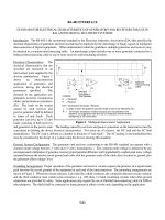
Figure 1.1. (a) Hardness of various cutting-tool materials as a function of temperature. (b)
Ranges of properties of various groups of materials.
Chap. 1: Cutting-Tool Materials
4
Tooling & Production/Chapter 1 2001
www.toolingandproduction.com
speed steel.
When applying cast alloy tools, their
brittleness should be kept in mind and
sufficient support should be provided at
all times. Cast alloys provide high abra-
sion resistance and are thus useful for
cutting scaly materials or those with
hard inclusions.
1.3 Cemented Tungsten Carbide
Tungsten carbide was discovered by
Henri Moissan in 1893 during a search
for a method of making artificial dia-
monds. Charging sugar and tungsten
oxide, he melted tungsten sub-carbide
in an arc furnace. The carbonized sugar
reduced the oxide and carburized the
tungsten. Moissan recorded that the
tungsten carbide was extremely hard,
approaching the hardness of diamond
and exceeding that of sapphire. It was
more than 16 times as heavy as water.
The material proved to be extremely
brittle and seriously limited its industri-
al use.
Commercial tungsten carbide with 6
percent cobalt binder was first produced
and marketed in Germany in 1926.
Production of the same carbide began in
the United States in 1928 and in Canada
in 1930.
At this time, hard carbides consisted
of the basic tungsten carbide system
with cobalt binders. These carbides
exhibited superior performance in the
machining of cast iron, nonferrous, and
non metallic materials, but were disap-
pointing when used for the machining
of steel.
Most of the subsequent developments
in the hard carbides have been modifi-
cations of the original patents, princi-
pally involving replacement of part or
all of the tungsten carbide with other
carbides, especially titanium carbide
and/or tantalum carbide. This led to the
development of the modern multi-car-
bide cutting tool materials permitting
the high speed machining of steel.
A new phenomenon was introduced
with the development of the cemented
carbides, again making higher speeds
possible. Previous cutting tool materi-
als, products of molten metallurgy,
depended largely upon heat treatment
for their properties and these properties
could, in turn, be destroyed by further
heat treatment. At high speeds, and
consequently high temperatures, these
products of molten metallurgy failed.
A different set of conditions exists
with the cemented carbides. The hard-
ness of the carbide is greater than that of
most other tool materials at room tem-
perature and it has the ability to retain it
hardness at elevated temperatures to a
greater degree, so that greater speeds
can be adequately supported.
1.3.1 Manufacture of Carbide
Products
The term “tungsten carbide” describes a
comprehensive family of hard carbide
compositions used for metal cutting
tools, dies of various types, and wear
parts. In general, these materials are
composed of the carbides of tungsten,
titanium, tantalum or some combination
of these, sintered or cemented in a
matrix binder, usually cobalt.
Blending: The first operation after
reduction of the tungsten compounds to
tungsten metal powder is the milling of
tungsten and carbon prior to the carbur-
izing operation. Here, 94 parts by
weight of tungsten and 6 parts by
weight of carbon, usually added in the
form of lamp black, are blended togeth-
er in a rotating mixer or ball mill. This
operation must be performed under
carefully controlled conditions in order
to insure optimum dispersion of the car-
bon in the tungsten. Carbide Blending
Equipment, better known as a Ball Mill,
is shown in Figure 1.2.
In order to provide the necessary
strength, a binding agent, usually cobalt
(Co) is added to the tungsten (WC) in
powder form and these two are ball
milled together for a period of several
days, to form a very intimate mixture.
Careful control of conditions, including
time, must be exercised to obtain a uni-
form, homogeneous product. Blended
Tungsten Carbide Powder is shown in
Figure 1.3.
Compacting: The most common
compacting method for grade powders
involves the use of a die, made to the
shape of the eventual product desired.
The size of the die must be greater than
the final product size to allow for
dimensional shrinkage which takes
place in the final sintering operation.
These dies are expensive, and usually
made with tungsten carbide liners.
Therefore sufficient number of the final
product (compacts) are required, to jus-
tify the expense involved in manufac-
turing a special die. Carbide
Figure 1.2. Carbide blending equipment,
better known as ball mill is used to ensure
optimum dispersion of the carbon within
the tungsten. (Courtesy American National
Carbide Co)
Figure 1.3. Blended tungsten carbide pow-
der is produced by mixing tungsten carbide
(WC) with a cobalt (Co) binder in a ball
milling process. (Courtesy American
National Carbide Co)
Figure 1.4. Carbide compacting equipment,
better known as a pill press, is used to pro-
duce carbide products in various shapes.
(Courtesy American National Carbide Co)
Chap. 1: Cutting-Tool Materials
www.toolingandproduction.com
Chapter 1/Tooling & Production
5
Compacting Equipment, better known
as a Pill Press, is shown in Figure 1.4.
Various pill pressed carbide parts are
shown in Figure 1.5.
If the quantities are not high, a larger
briquette, or billet may be pressed. This
billet may then be cut up (usually after
pre-sintering) into smaller units and
shaped or preformed to the required
configuration, and again, allowance
must be made to provide for shrinkage.
Ordinarily pressures used in these cold
compacting operations are in the neigh-
borhood of 30,000 PSI. Various carbide
preformed parts are shown in Figure
1.6.
A second compacting method is the
hot pressing of grade powders in
graphite dies at the sintering tempera-
ture. After cooling, the part has attained
full hardness. Because the graphite dies
are expendable, this system is generally
used only when the part to be produced
is too large for cold pressing and sinter-
ing.
A third compacting method, usually
used for large pieces, is isostatic press-
ing. Powders are placed into a closed,
flexible container which is then sus-
pended in a liquid in a closed pressure
vessel. Pressure in the liquid is built up
to the point where the powders become
properly compacted. This system is
advantageous for pressing large pieces,
because the pressure acting on the pow-
ders operates equally from all direc-
tions, resulting in a compact of uniform
pressed density.
Sintering: Sintering of tungsten -
cobalt (WC-Co) compacts is performed
with the cobalt binder in liquid phase.
The compact is heated in hydrogen
atmosphere or vacuum furnaces to tem-
peratures ranging from 2500 to 2900
degrees Fahrenheit, depending on the
composition. Both time and tempera-
ture must be carefully adjusted in com-
bination, to effect optimum control over
properties and geometry. The compact
will shrink approximately 16 percent on
linear dimensions, or 40 percent in vol-
ume. The exact amount of shrinkage
depends on several factors including
particle size of the powders and the
composition of the grade. Control of
size and shape is most important and is
least predictable during the cooling
cycle. This is particularly true with
those grades of cemented carbides with
higher cobalt contents.
With cobalt having a lesser density
than tungsten, it occupies a greater part
of the volume than would be indicated
by the rated cobalt content of the grade;
and because cobalt contents are general-
ly a much higher percentage of the mass
in liquid phase, extreme care is required
to control and predict with accuracy the
magnitude and direction of shrinkage.
Figure 1.7 shows carbide parts being
loaded into a Sintering Furnace.
Figure 1.5. Various carbide compacts,
which are produced with special dies
mounted into pill presses. (Courtesy
American National Carbide Co)
Figure 1.6. If quantities are not high, presin-
tered billets are shaped or preformed into
required shapes. (Courtesy Duramet
Corporation)
Figure 1.7. Carbide parts are loaded into a
sintering furnace, where they are heated to
temperatures ranging from 2500° to
2900°F. (Courtesy American National
Carbide Co)
Figure 1.8. Schematic diagram of the cemented tungsten carbide manufacturing process.