Tài liệu Tài liệu Diezel 1410 P13 pptx
Bạn đang xem bản rút gọn của tài liệu. Xem và tải ngay bản đầy đủ của tài liệu tại đây (202.34 KB, 14 trang )
13
REDUCTION GEARS
A. REDUCTION GEAR UNITS
13A1. Function and type. The main
diesel engines are directly connected to
the main generators which furnish
power to the main motors or battery
through the control cubicle. Two types
of main drive installations are now in
use in modern fleet type submarines.
The older type which is at present used
in about 95 percent of our submarines
consists of four main motors arranged
in pairs to drive each of the propeller
shafts through a reduction gear. This
type of installation uses a single control
cubicle. The latest type of main drive
installation consists of a split control
cubicle and two large, slow-speed,
double-armature motors which are
directly connected to the propeller
shaft. Each section of the split control
cubicle is designed primarily to control
propulsion on its particular side. It is
possible, however, to tie the two sides
of the split cubicle together and
therefore use port engines on the
starboard screw and vice versa.
This description of reduction gears is
limited to the older type installation.
Each reduction gear reduces the high
main motor speed of approximately
1300 rpm to the propeller shaft speed of
280 rpm. The ratio of reduction is
determined by the maximum efficiency
obtainable from the propellers without
loss of power at varying motor and
propeller speeds.
The gears are single reduction, double
helical type, a right- and left-hand helix
being used to balance the fore and aft
components of the tooth pressure.
The reduction gear assembly consists
essentially of two main motor pinions
forged and cut integral with the pinion
shafts, one main gear or bull gear which
is connected to the propeller shaft, and a
lubricating oil pump gear which is geared
to the inner pinion shaft. The forward
ends of the pinion shafts are connected to
their respective motors through flexible
couplings. Each pinion shaft is supported
by a cylindrical type bearing at each end.
The main gear is pressed and keyed to
the gear shaft. The aft end of the shaft is
coupled to the propeller shaft. On the
forward end of the main gear shaft is
mounted the collar of the main thrust
bearing which absorbs the propeller
thrust. The gear and shaft are carried on
two sleeve bearings.
The sleeve bearings consist of steel shells
lined with babbitt. The bearing shells are
split
These helical gears produce a smoother
action and avoid the tooth check of spur
gears.
13A2. Description and operation.
With the exception of minor differences
in design, gear units produced by
various manufacturers and installed on
fleet type submarines today are similar.
Specifications to which they are built
will be found in the manufacturer's
instruction book pertaining to the unit
in question. The two units used on each
ship are alike except that one is for port
propulsion and the other for starboard
propulsion. Facing aft, the port shaft
rotates clockwise, and the starboard
shaft rotates counterclockwise.
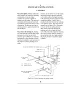
Figure 13-1. Reduction gear, top case
removed.
261
Figure 13-2. Sectional views of reduction gear.
262
and the two halves of each shell are
held in alignment by dowels set in the
lower half. Dowels in the bearing caps
prevent the shells from rotating. The
lubrication of the bearings is explained
in Section 13A4f.
13A3. Flexible couplings between
pinion and motor shafts. The
An accurate record of all repairs,
adjustments, readings, and casualties
should be kept in the machinery history.
b. Unusual sounds. A properly operating
reduction gear has a certain definite
sound which the trained operator can
easily recognize. The cause of any
unusual noises should be investigated,
couplings between the two main motor
armature shafts and the pinion shafts of
the reduction gear are of the enclosed
flexible type. Each coupling consists
essentially of two hubs with external
spur gears, and two sleeves with
internal spur gears. The hubs are
pressed on and keyed to their respective
shafts. The floating sleeves fit around
the hubs so that the spur gear teeth are
permanently meshed. The floating
sleeves are bolted together.
This type of coupling provides
longitudinal flexibility between the
driving and driven shafts and thereby
permits the pinion to trail the main
gear. Movement of the main gear is in
turn limited by the clearance in the
thrust bearing. The coupling permits a
small amount of misalignment of the
hubs to occur without causing
operational difficulties. However, it is
not advisable to operate continuously
with the hubs out of alignment because
the coupling is not intended to function
as a universal joint. Continuous
operation with the hubs out of
alignment will result in excessive
friction and gear teeth wear, and
eventually will cause a breakdown.
The couplings are lubricated by a
continuous stream of oil supplied by
the main motor and reduction gear
lubricating oil pump. Oil enters through
a nozzle and after passing between the
gear teeth is discharged through holes
in the sleeve.
13A4. Maintenance. a. Machinery
history. It is of great importance that
the machinery history contain a
complete record of the installation from
the time of commissioning. Complete
installation data as furnished by the
and the gears should be operated with
caution until the source is located and
remedied.
c. Tooth contact. It is essential, for prope
r
operation of the gears, that the total tooth
pressure be uniformly distributed over
the total area of the tooth faces. This is
accomplished by accurate alignment, and
adherence to the designed clearance
limits. Alignment should be checked at
the time the gear is installed, during each
major overhaul, and after any casualty
severe enough to threaten the alignment.
Operating gears with faulty alignment are
detrimental to the life and performance of
the teeth. Continued quiet operation and
good tooth contact are the best
indications of proper tooth alignment.
d. Backlash. Backlash is measured by
locking the main gear in its forward
position and then moving each pinion
just far enough forward and aft to make
firm contact each way. The total
lengthwise movement measured when
doing this is the axial backlash. The
backlash will increase with wear, and it
can increase considerably without
causing trouble. The actual longitudinal
movement, as measured at the time the
unit was built at the factory, should be
found stamped on all pinion shafts except
spares, and should be recorded in the
machinery history. This measurement is
the minimum allowable backlash.
e. Flexible couplings. The coupling
backlash should be checked at regular
intervals to see that it has not increased
excessively. A dial indicator is used to
measure the total backlash without
dismantling the coupling. The one shaft
is held stationary, and the dial indicator is
mounted on the opposite or moving shaft
with the indicator needle on some Dart of
contractor should be entered in the
machinery index by prospective
engineer officers at the contractor's
yard. This should include the original
bearing crown thickness or bridge gage
readings, bearing clearances, thrust
settings and clearances, and tooth
clearances (backlash and root) of the
gear wheel and pinion teeth. It is
essential that these data be on hand
when the alignment is subsequently
checked.
the coupling housing. By twisting the
movable shaft back and forth without
allowing the stationary shaft to move, the
total backlash will be indicated on the
dial indicator.
263
The backlash when found should be
checked with the recorded initial
backlash. If subsequent wear has
increased the backlash to twice the
original amount, replacement of the
coupling should be considered.
Since the condition of the bearing
surfaces depends upon the axial
alignment of the shafts, regular
inspection should include a check to
see that proper alignment is maintained.
To check the alignment, the flexible
coupling must first be dismantled. To
accomplish this, the manufacturer's
instruction book should be consulted.
f. Bearings. All of the bearing caps may
be removed for bearing inspection or
replacement without disturbing the gear
case. The pinions are light enough so
that no trouble should be experienced
when rolling out the lower halves of the
pinion bearings once the shaft has been
raised.
When assembling, all bearing shells
should be replaced in their original
positions. Old cement should be
cleaned off the mating surfaces of the
bearing caps, end caps, and case, and a
g. Bearing wear. The amount of wear of
reduction gear bearings must not be
allowed to become sufficiently great to
cause incorrect gear tooth contact. The
designed clearances, load diagrams, and
methods of measuring bearing wear are
given in the manufacturer's instruction
book pertaining to the unit in question.
13A5. Special precautions. a. In case of
churning or emulsification of the oil in
the gear case, the gear must be slowed or
stopped until the defect is remedied.
b. If for any reason, the supply of
lubricating oil to the gears fails, the gears
should be immediately stopped until the
cause can be located and remedied.
c. When bearings are known to have been
overheated, gears should not be operated,
except in cases of extreme emergency,
until bearings have been examined and
the defects remedied.
d. If excessive flaking of metal from gear
teeth occurs, the gears should not be
adjusted, except in case of emergency,
until the cause has been determined. Care
should be taken, however, to prevent the
entry of the metal flakes into the general