PLC MasterK-80S
Bạn đang xem bản rút gọn của tài liệu. Xem và tải ngay bản đầy đủ của tài liệu tại đây (4.77 MB, 246 trang )
◎ Contents ◎
◎◎
◎
Chapter 1. General∙∙∙∙∙∙∙∙∙∙∙∙∙∙∙∙∙∙∙∙∙∙∙∙∙∙∙∙∙∙∙∙∙∙∙∙∙∙∙∙∙∙∙∙∙∙∙∙∙∙∙∙∙∙∙∙∙∙∙∙∙∙∙∙∙∙∙∙∙∙∙∙∙∙∙∙∙∙∙∙∙∙∙∙∙∙∙∙∙∙∙∙∙ 1-1~1-6
1.1
Guide to Use this Manual
∙∙∙∙∙∙∙∙∙∙∙∙∙∙∙∙∙∙∙∙∙∙∙∙∙∙∙∙∙∙∙∙∙∙∙∙∙∙∙∙∙∙∙∙∙∙∙∙∙∙∙∙∙∙∙∙∙∙∙∙∙∙∙∙∙∙∙∙∙∙∙∙∙∙∙∙∙∙∙∙∙∙∙ 1-1
1.2
Features
∙∙∙∙∙∙∙∙∙∙∙∙∙∙∙∙∙∙∙∙∙∙∙∙∙∙∙∙∙∙∙∙∙∙∙∙∙∙∙∙∙∙∙∙∙∙∙∙∙∙∙∙∙∙∙∙∙∙∙∙∙∙∙∙∙∙∙∙∙∙∙∙∙∙∙∙∙∙∙∙∙∙∙∙∙∙∙∙∙∙∙∙∙∙∙∙∙∙∙∙∙∙∙∙∙∙∙∙∙ 1-2
1.3
Terminology
∙∙∙∙∙∙∙∙∙∙∙∙∙∙∙∙∙∙∙∙∙∙∙∙∙∙∙∙∙∙∙∙∙∙∙∙∙∙∙∙∙∙∙∙∙∙∙∙∙∙∙∙∙∙∙∙∙∙∙∙∙∙∙∙∙∙∙∙∙∙∙∙∙∙∙∙∙∙∙∙∙∙∙∙∙∙∙∙∙∙∙∙∙∙∙∙∙∙∙∙∙∙∙∙ 1-4
Chapter 2. System Configuration ∙∙∙∙∙∙∙∙∙∙∙∙∙∙∙∙∙∙∙∙∙∙∙∙∙∙∙∙∙∙∙∙∙∙∙∙∙∙∙∙∙∙∙∙∙∙∙∙∙∙∙∙∙∙∙∙∙∙∙∙∙∙∙∙∙∙∙∙∙∙∙∙ 2-1~2-6
2.1
Overall Configuration
∙∙∙∙∙∙∙∙∙∙∙∙∙∙∙∙∙∙∙∙∙∙∙∙∙∙∙∙∙∙∙∙∙∙∙∙∙∙∙∙∙∙∙∙∙∙∙∙∙∙∙∙∙∙∙∙∙∙∙∙∙∙∙∙∙∙∙∙∙∙∙∙∙∙∙∙∙∙∙∙∙∙∙∙∙∙∙∙∙ 2-1
2.1.1 Basic system∙∙∙∙∙∙∙∙∙∙∙∙∙∙∙∙∙∙∙∙∙∙∙∙∙∙∙∙∙∙∙∙∙∙∙∙∙∙∙∙∙∙∙∙∙∙∙∙∙∙∙∙∙∙∙∙∙∙∙∙∙∙∙∙∙∙∙∙∙∙∙∙∙∙∙∙∙∙∙∙∙∙∙∙∙∙∙∙∙∙∙∙∙∙∙∙∙∙ 2-2
2.1.2 Cnet I/F System ∙∙∙∙∙∙∙∙∙∙∙∙∙∙∙∙∙∙∙∙∙∙∙∙∙∙∙∙∙∙∙∙∙∙∙∙∙∙∙∙∙∙∙∙∙∙∙∙∙∙∙∙∙∙∙∙∙∙∙∙∙∙∙∙∙∙∙∙∙∙∙∙∙∙∙∙∙∙∙∙∙∙∙∙∙∙∙∙∙∙∙∙∙∙ 2-2
2.2
Product functional model
∙∙∙∙∙∙∙∙∙∙∙∙∙∙∙∙∙∙∙∙∙∙∙∙∙∙∙∙∙∙∙∙∙∙∙∙∙∙∙∙∙∙∙∙∙∙∙∙∙∙∙∙∙∙∙∙∙∙∙∙∙∙∙∙∙∙∙∙∙∙∙∙∙∙∙∙∙∙∙∙∙∙∙∙ 2-4
2.2.1 Product function Block∙∙∙∙∙∙∙∙∙∙∙∙∙∙∙∙∙∙∙∙∙∙∙∙∙∙∙∙∙∙∙∙∙∙∙∙∙∙∙∙∙∙∙∙∙∙∙∙∙∙∙∙∙∙∙∙∙∙∙∙∙∙∙∙∙∙∙∙∙∙∙∙∙∙∙∙∙∙∙∙∙∙∙∙∙∙ 2-4
2.2.2 GM7 Series System Equipment Product∙∙∙∙∙∙∙∙∙∙∙∙∙∙∙∙∙∙∙∙∙∙∙∙∙∙∙∙∙∙∙∙∙∙∙∙∙∙∙∙∙∙∙∙∙∙∙∙∙∙∙∙∙∙∙∙∙∙∙∙∙∙∙ 2-5
Chapter 3. GENERAL SPECIFICATION ∙∙∙∙∙∙∙∙∙∙∙∙∙∙∙∙∙∙∙∙∙∙∙∙∙∙∙∙∙∙∙∙∙∙∙∙∙∙∙∙∙∙∙∙∙∙∙∙∙∙∙∙∙∙∙∙∙∙∙∙∙∙∙∙∙∙∙∙∙∙∙ 3-1
3.1
General specifications
∙∙∙∙∙∙∙∙∙∙∙∙∙∙∙∙∙∙∙∙∙∙∙∙∙∙∙∙∙∙∙∙∙∙∙∙∙∙∙∙∙∙∙∙∙∙∙∙∙∙∙∙∙∙∙∙∙∙∙∙∙∙∙∙∙∙∙∙∙∙∙∙∙∙∙∙∙∙∙∙∙∙∙∙∙∙∙∙ 3-1
Chapter 4. Names of Parts∙∙∙∙∙∙∙∙∙∙∙∙∙∙∙∙∙∙∙∙∙∙∙∙∙∙∙∙∙∙∙∙∙∙∙∙∙∙∙∙∙∙∙∙∙∙∙∙∙∙∙∙∙∙∙∙∙∙∙∙∙∙∙∙∙∙∙∙∙∙∙∙∙∙∙∙∙∙∙∙∙∙ 4-1~4-4
4.1
Base Unit
∙∙∙∙∙∙∙∙∙∙∙∙∙∙∙∙∙∙∙∙∙∙∙∙∙∙∙∙∙∙∙∙∙∙∙∙∙∙∙∙∙∙∙∙∙∙∙∙∙∙∙∙∙∙∙∙∙∙∙∙∙∙∙∙∙∙∙∙∙∙∙∙∙∙∙∙∙∙∙∙∙∙∙∙∙∙∙∙∙∙∙∙∙∙∙∙∙∙∙∙∙∙∙∙∙∙∙ 4-1
4.1.1 10-point basic unit ∙∙∙∙∙∙∙∙∙∙∙∙∙∙∙∙∙∙∙∙∙∙∙∙∙∙∙∙∙∙∙∙∙∙∙∙∙∙∙∙∙∙∙∙∙∙∙∙∙∙∙∙∙∙∙∙∙∙∙∙∙∙∙∙∙∙∙∙∙∙∙∙∙∙∙∙∙∙∙∙∙∙∙∙∙∙∙∙∙∙∙ 4-3
4.1.2 20-point basic unit ∙∙∙∙∙∙∙∙∙∙∙∙∙∙∙∙∙∙∙∙∙∙∙∙∙∙∙∙∙∙∙∙∙∙∙∙∙∙∙∙∙∙∙∙∙∙∙∙∙∙∙∙∙∙∙∙∙∙∙∙∙∙∙∙∙∙∙∙∙∙∙∙∙∙∙∙∙∙∙∙∙∙∙∙∙∙∙∙∙∙∙ 4-3
4.1.3 30-points Basic Unit ∙∙∙∙∙∙∙∙∙∙∙∙∙∙∙∙∙∙∙∙∙∙∙∙∙∙∙∙∙∙∙∙∙∙∙∙∙∙∙∙∙∙∙∙∙∙∙∙∙∙∙∙∙∙∙∙∙∙∙∙∙∙∙∙∙∙∙∙∙∙∙∙∙∙∙∙∙∙∙∙∙∙∙∙∙∙∙∙∙ 4-4
4.1.4 40-Points Basic Unit ∙∙∙∙∙∙∙∙∙∙∙∙∙∙∙∙∙∙∙∙∙∙∙∙∙∙∙∙∙∙∙∙∙∙∙∙∙∙∙∙∙∙∙∙∙∙∙∙∙∙∙∙∙∙∙∙∙∙∙∙∙∙∙∙∙∙∙∙∙∙∙∙∙∙∙∙∙∙∙∙∙∙∙∙∙∙∙∙ 4-4
4.1.5 60-Points Basic Unit ∙∙∙∙∙∙∙∙∙∙∙∙∙∙∙∙∙∙∙∙∙∙∙∙∙∙∙∙∙∙∙∙∙∙∙∙∙∙∙∙∙∙∙∙∙∙∙∙∙∙∙∙∙∙∙∙∙∙∙∙∙∙∙∙∙∙∙∙∙∙∙∙∙∙∙∙∙∙∙∙∙∙∙∙∙∙∙∙ 4-4
4.2
Expansion / Option Module
∙∙∙∙∙∙∙∙∙∙∙∙∙∙∙∙∙∙∙∙∙∙∙∙∙∙∙∙∙∙∙∙∙∙∙∙∙∙∙∙∙∙∙∙∙∙∙∙∙∙∙∙∙∙∙∙∙∙∙∙∙∙∙∙∙∙∙∙∙∙∙∙∙∙∙∙∙∙∙∙ 4-5
4.2.1 Digital I/O Module∙∙∙∙∙∙∙∙∙∙∙∙∙∙∙∙∙∙∙∙∙∙∙∙∙∙∙∙∙∙∙∙∙∙∙∙∙∙∙∙∙∙∙∙∙∙∙∙∙∙∙∙∙∙∙∙∙∙∙∙∙∙∙∙∙∙∙∙∙∙∙∙∙∙∙∙∙∙∙∙∙∙∙∙∙∙∙∙∙∙∙∙ 4-5
4.2.2 A/D
・
D/A Combination Module ∙∙∙∙∙∙∙∙∙∙∙∙∙∙∙∙∙∙∙∙∙∙∙∙∙∙∙∙∙∙∙∙∙∙∙∙∙∙∙∙∙∙∙∙∙∙∙∙∙∙∙∙∙∙∙∙∙∙∙∙∙∙∙∙∙∙∙∙∙ 4-5
4.2.3
Analogue timer Module ∙∙∙∙∙∙∙∙∙∙∙∙∙∙∙∙∙∙∙∙∙∙∙∙∙∙∙∙∙∙∙∙∙∙∙∙∙∙∙∙∙∙∙∙∙∙∙∙∙∙∙∙∙∙∙∙∙∙∙∙∙∙∙∙∙∙∙∙∙∙∙∙∙∙∙∙∙∙∙∙∙∙∙∙4–5
4.2.4 Option Module ∙∙∙∙∙∙∙∙∙∙∙∙∙∙∙∙∙∙∙∙∙∙∙∙∙∙∙∙∙∙∙∙∙∙∙∙∙∙∙∙∙∙∙∙∙∙∙∙∙∙∙∙∙∙∙∙∙∙∙∙∙∙∙∙∙∙∙∙∙∙∙∙∙∙∙∙∙∙∙∙∙∙∙∙∙∙∙∙∙∙∙∙∙∙∙∙ 4-6
Chapter 5. CPU ∙∙∙∙∙∙∙∙∙∙∙∙∙∙∙∙∙∙∙∙∙∙∙∙∙∙∙∙∙∙∙∙∙∙∙∙∙∙∙∙∙∙∙∙∙∙∙∙∙∙∙∙∙∙∙∙∙∙∙∙∙∙∙∙∙∙∙∙∙∙∙∙∙∙∙∙∙∙∙∙∙∙∙∙∙∙∙∙∙∙∙∙∙∙∙ 5-1~5-42
5.1
Specifications
∙∙∙∙∙∙∙∙∙∙∙∙∙∙∙∙∙∙∙∙∙∙∙∙∙∙∙∙∙∙∙∙∙∙∙∙∙∙∙∙∙∙∙∙∙∙∙∙∙∙∙∙∙∙∙∙∙∙∙∙∙∙∙∙∙∙∙∙∙∙∙∙∙∙∙∙∙∙∙∙∙∙∙∙∙∙∙∙∙∙∙∙∙∙∙∙∙∙∙∙∙ 5-1
5.2
Operation Processing
∙∙∙∙∙∙∙∙∙∙∙∙∙∙∙∙∙∙∙∙∙∙∙∙∙∙∙∙∙∙∙∙∙∙∙∙∙∙∙∙∙∙∙∙∙∙∙∙∙∙∙∙∙∙∙∙∙∙∙∙∙∙∙∙∙∙∙∙∙∙∙∙∙∙∙∙∙∙∙∙∙∙∙∙∙∙∙∙∙ 5-3
5.2.1 Operation Processing Method ∙∙∙∙∙∙∙∙∙∙∙∙∙∙∙∙∙∙∙∙∙∙∙∙∙∙∙∙∙∙∙∙∙∙∙∙∙∙∙∙∙∙∙∙∙∙∙∙∙∙∙∙∙∙∙∙∙∙∙∙∙∙∙∙∙∙∙∙∙∙∙∙∙∙∙∙ 5-3
5.2.2 Operation Processing at momentary power failure occurrence ∙∙∙∙∙∙∙∙∙∙∙∙∙∙∙∙∙∙∙∙∙∙∙∙∙∙∙∙∙∙∙∙∙∙ 5-4
5.2.3 Scan time ∙∙∙∙∙∙∙∙∙∙∙∙∙∙∙∙∙∙∙∙∙∙∙∙∙∙∙∙∙∙∙∙∙∙∙∙∙∙∙∙∙∙∙∙∙∙∙∙∙∙∙∙∙∙∙∙∙∙∙∙∙∙∙∙∙∙∙∙∙∙∙∙∙∙∙∙∙∙∙∙∙∙∙∙∙∙∙∙∙∙∙∙∙∙∙∙∙∙∙∙∙∙ 5-5
5.2.4 Scan-watchdog timer ∙∙∙∙∙∙∙∙∙∙∙∙∙∙∙∙∙∙∙∙∙∙∙∙∙∙∙∙∙∙∙∙∙∙∙∙∙∙∙∙∙∙∙∙∙∙∙∙∙∙∙∙∙∙∙∙∙∙∙∙∙∙∙∙∙∙∙∙∙∙∙∙∙∙∙∙∙∙∙∙∙∙∙∙∙∙∙ 5-5
5.2.5 Timer processing ∙∙∙∙∙∙∙∙∙∙∙∙∙∙∙∙∙∙∙∙∙∙∙∙∙∙∙∙∙∙∙∙∙∙∙∙∙∙∙∙∙∙∙∙∙∙∙∙∙∙∙∙∙∙∙∙∙∙∙∙∙∙∙∙∙∙∙∙∙∙∙∙∙∙∙∙∙∙∙∙∙∙∙∙∙∙∙∙∙∙∙∙ 5-6
5.2.6 Counter processing ∙∙∙∙∙∙∙∙∙∙∙∙∙∙∙∙∙∙∙∙∙∙∙∙∙∙∙∙∙∙∙∙∙∙∙∙∙∙∙∙∙∙∙∙∙∙∙∙∙∙∙∙∙∙∙∙∙∙∙∙∙∙∙∙∙∙∙∙∙∙∙∙∙∙∙∙∙∙∙∙∙∙∙∙∙∙∙∙∙ 5-8
5.3
Program
∙∙∙∙∙∙∙∙∙∙∙∙∙∙∙∙∙∙∙∙∙∙∙∙∙∙∙∙∙∙∙∙∙∙∙∙∙∙∙∙∙∙∙∙∙∙∙∙∙∙∙∙∙∙∙∙∙∙∙∙∙∙∙∙∙∙∙∙∙∙∙∙∙∙∙∙∙∙∙∙∙∙∙∙∙∙∙∙∙∙∙∙∙∙∙∙∙∙∙∙∙∙∙∙∙∙∙∙5-10
5.3.1 Program configuration ∙∙∙∙∙∙∙∙∙∙∙∙∙∙∙∙∙∙∙∙∙∙∙∙∙∙∙∙∙∙∙∙∙∙∙∙∙∙∙∙∙∙∙∙∙∙∙∙∙∙∙∙∙∙∙∙∙∙∙∙∙∙∙∙∙∙∙∙∙∙∙∙∙∙∙∙∙∙∙∙∙∙∙∙∙5-10
5.3.2 Program execution procedure ∙∙∙∙∙∙∙∙∙∙∙∙∙∙∙∙∙∙∙∙∙∙∙∙∙∙∙∙∙∙∙∙∙∙∙∙∙∙∙∙∙∙∙∙∙∙∙∙∙∙∙∙∙∙∙∙∙∙∙∙∙∙∙∙∙∙∙∙∙∙∙∙∙∙∙ 5-11
5.3.3 Task ∙∙∙∙∙∙∙∙∙∙∙∙∙∙∙∙∙∙∙∙∙∙∙∙∙∙∙∙∙∙∙∙∙∙∙∙∙∙∙∙∙∙∙∙∙∙∙∙∙∙∙∙∙∙∙∙∙∙∙∙∙∙∙∙∙∙∙∙∙∙∙∙∙∙∙∙∙∙∙∙∙∙∙∙∙∙∙∙∙∙∙∙∙∙∙∙∙∙∙∙∙∙∙∙∙∙∙∙5-14
5.3.4 Error handling∙∙∙∙∙∙∙∙∙∙∙∙∙∙∙∙∙∙∙∙∙∙∙∙∙∙∙∙∙∙∙∙∙∙∙∙∙∙∙∙∙∙∙∙∙∙∙∙∙∙∙∙∙∙∙∙∙∙∙∙∙∙∙∙∙∙∙∙∙∙∙∙∙∙∙∙∙∙∙∙∙∙∙∙∙∙∙∙∙∙∙∙∙∙∙ 5–21
5.3.5 Precautions when using special modules ∙∙∙∙∙∙∙∙∙∙∙∙∙∙∙∙∙∙∙∙∙∙∙∙∙∙∙∙∙∙∙∙∙∙∙∙∙∙∙∙∙∙∙∙∙∙∙∙∙∙∙∙∙∙∙∙∙∙∙ 5–22
5.4
Operation modes
∙∙∙∙∙∙∙∙∙∙∙∙∙∙∙∙∙∙∙∙∙∙∙∙∙∙∙∙∙∙∙∙∙∙∙∙∙∙∙∙∙∙∙∙∙∙∙∙∙∙∙∙∙∙∙∙∙∙∙∙∙∙∙∙∙∙∙∙∙∙∙∙∙∙∙∙∙∙∙∙∙∙∙∙∙∙∙∙∙∙∙∙∙∙5-23
5.4.1 RUN mode ∙∙∙∙∙∙∙∙∙∙∙∙∙∙∙∙∙∙∙∙∙∙∙∙∙∙∙∙∙∙∙∙∙∙∙∙∙∙∙∙∙∙∙∙∙∙∙∙∙∙∙∙∙∙∙∙∙∙∙∙∙∙∙∙∙∙∙∙∙∙∙∙∙∙∙∙∙∙∙∙∙∙∙∙∙∙∙∙∙∙∙∙∙∙∙∙∙∙∙5-23
5.4.2 STOP mode ∙∙∙∙∙∙∙∙∙∙∙∙∙∙∙∙∙∙∙∙∙∙∙∙∙∙∙∙∙∙∙∙∙∙∙∙∙∙∙∙∙∙∙∙∙∙∙∙∙∙∙∙∙∙∙∙∙∙∙∙∙∙∙∙∙∙∙∙∙∙∙∙∙∙∙∙∙∙∙∙∙∙∙∙∙∙∙∙∙∙∙∙∙∙∙∙∙∙5-24
5.4.3 PAUSE mode ∙∙∙∙∙∙∙∙∙∙∙∙∙∙∙∙∙∙∙∙∙∙∙∙∙∙∙∙∙∙∙∙∙∙∙∙∙∙∙∙∙∙∙∙∙∙∙∙∙∙∙∙∙∙∙∙∙∙∙∙∙∙∙∙∙∙∙∙∙∙∙∙∙∙∙∙∙∙∙∙∙∙∙∙∙∙∙∙∙∙∙∙∙∙∙∙5-24
5.4.4 DEBUG mode ∙∙∙∙∙∙∙∙∙∙∙∙∙∙∙∙∙∙∙∙∙∙∙∙∙∙∙∙∙∙∙∙∙∙∙∙∙∙∙∙∙∙∙∙∙∙∙∙∙∙∙∙∙∙∙∙∙∙∙∙∙∙∙∙∙∙∙∙∙∙∙∙∙∙∙∙∙∙∙∙∙∙∙∙∙∙∙∙∙∙∙∙∙∙∙5-24
5.4.5 Operation mode Change∙∙∙∙∙∙∙∙∙∙∙∙∙∙∙∙∙∙∙∙∙∙∙∙∙∙∙∙∙∙∙∙∙∙∙∙∙∙∙∙∙∙∙∙∙∙∙∙∙∙∙∙∙∙∙∙∙∙∙∙∙∙∙∙∙∙∙∙∙∙∙∙∙∙∙∙∙∙∙∙∙∙5-25
5.5
Functions
∙∙∙∙∙∙∙∙∙∙∙∙∙∙∙∙∙∙∙∙∙∙∙∙∙∙∙∙∙∙∙∙∙∙∙∙∙∙∙∙∙∙∙∙∙∙∙∙∙∙∙∙∙∙∙∙∙∙∙∙∙∙∙∙∙∙∙∙∙∙∙∙∙∙∙∙∙∙∙∙∙∙∙∙∙∙∙∙∙∙∙∙∙∙∙∙∙∙∙∙∙∙∙∙∙∙5-27
5.5.1 Restart mode ∙∙∙∙∙∙∙∙∙∙∙∙∙∙∙∙∙∙∙∙∙∙∙∙∙∙∙∙∙∙∙∙∙∙∙∙∙∙∙∙∙∙∙∙∙∙∙∙∙∙∙∙∙∙∙∙∙∙∙∙∙∙∙∙∙∙∙∙∙∙∙∙∙∙∙∙∙∙∙∙∙∙∙∙∙∙∙∙∙∙∙∙∙∙∙∙5-27
5.5.2 Self-diagnosis∙∙∙∙∙∙∙∙∙∙∙∙∙∙∙∙∙∙∙∙∙∙∙∙∙∙∙∙∙∙∙∙∙∙∙∙∙∙∙∙∙∙∙∙∙∙∙∙∙∙∙∙∙∙∙∙∙∙∙∙∙∙∙∙∙∙∙∙∙∙∙∙∙∙∙∙∙∙∙∙∙∙∙∙∙∙∙∙∙∙∙∙∙∙∙∙5-29
5.5.3 Remote function∙∙∙∙∙∙∙∙∙∙∙∙∙∙∙∙∙∙∙∙∙∙∙∙∙∙∙∙∙∙∙∙∙∙∙∙∙∙∙∙∙∙∙∙∙∙∙∙∙∙∙∙∙∙∙∙∙∙∙∙∙∙∙∙∙∙∙∙∙∙∙∙∙∙∙∙∙∙∙∙∙∙∙∙∙∙∙∙∙∙∙∙∙5-29
5.5.4 I/O Force On/Off function ∙∙∙∙∙∙∙∙∙∙∙∙∙∙∙∙∙∙∙∙∙∙∙∙∙∙∙∙∙∙∙∙∙∙∙∙∙∙∙∙∙∙∙∙∙∙∙∙∙∙∙∙∙∙∙∙∙∙∙∙∙∙∙∙∙∙∙∙∙∙∙∙∙∙∙∙∙∙∙∙∙5-30
5.5.5 Direct I/O operation function ∙∙∙∙∙∙∙∙∙∙∙∙∙∙∙∙∙∙∙∙∙∙∙∙∙∙∙∙∙∙∙∙∙∙∙∙∙∙∙∙∙∙∙∙∙∙∙∙∙∙∙∙∙∙∙∙∙∙∙∙∙∙∙∙∙∙∙∙∙∙∙∙∙∙∙∙∙5-31
5.5.6 External device error diagnosis function ∙∙∙∙∙∙∙∙∙∙∙∙∙∙∙∙∙∙∙∙∙∙∙∙∙∙∙∙∙∙∙∙∙∙∙∙∙∙∙∙∙∙∙∙∙∙∙∙∙∙∙∙∙∙∙∙∙∙∙∙∙∙5-32
5.6
Memory Configuration
∙∙∙∙∙∙∙∙∙∙∙∙∙∙∙∙∙∙∙∙∙∙∙∙∙∙∙∙∙∙∙∙∙∙∙∙∙∙∙∙∙∙∙∙∙∙∙∙∙∙∙∙∙∙∙∙∙∙∙∙∙∙∙∙∙∙∙∙∙∙∙∙∙∙∙∙∙∙∙∙∙∙∙∙∙∙ 5–34
5.7
I/O No. Allocation Method
∙∙∙∙∙∙∙∙∙∙∙∙∙∙∙∙∙∙∙∙∙∙∙∙∙∙∙∙∙∙∙∙∙∙∙∙∙∙∙∙∙∙∙∙∙∙∙∙∙∙∙∙∙∙∙∙∙∙∙∙∙∙∙∙∙∙∙∙∙∙∙∙∙∙∙∙∙∙∙∙ 5–36
5.8
Built-in Flash Memory
∙∙∙∙∙∙∙∙∙∙∙∙∙∙∙∙∙∙∙∙∙∙∙∙∙∙∙∙∙∙∙∙∙∙∙∙∙∙∙∙∙∙∙∙∙∙∙∙∙∙∙∙∙∙∙∙∙∙∙∙∙∙∙∙∙∙∙∙∙∙∙∙∙∙∙∙∙∙∙∙∙∙∙∙∙∙ 5–35
5.8.1 Structure ∙∙∙∙∙∙∙∙∙∙∙∙∙∙∙∙∙∙∙∙∙∙∙∙∙∙∙∙∙∙∙∙∙∙∙∙∙∙∙∙∙∙∙∙∙∙∙∙∙∙∙∙∙∙∙∙∙∙∙∙∙∙∙∙∙∙∙∙∙∙∙∙∙∙∙∙∙∙∙∙∙∙∙∙∙∙∙∙∙∙∙∙∙∙∙∙∙∙∙∙∙∙5-36
5.8.2 Usage∙∙∙∙∙∙∙∙∙∙∙∙∙∙∙∙∙∙∙∙∙∙∙∙∙∙∙∙∙∙∙∙∙∙∙∙∙∙∙∙∙∙∙∙∙∙∙∙∙∙∙∙∙∙∙∙∙∙∙∙∙∙∙∙∙∙∙∙∙∙∙∙∙∙∙∙∙∙∙∙∙∙∙∙∙∙∙∙∙∙∙∙∙∙∙∙∙∙∙∙∙∙∙∙∙∙5-37
5.9
External Memory Module
∙∙∙∙∙∙∙∙∙∙∙∙∙∙∙∙∙∙∙∙∙∙∙∙∙∙∙∙∙∙∙∙∙∙∙∙∙∙∙∙∙∙∙∙∙∙∙∙∙∙∙∙∙∙∙∙∙∙∙∙∙∙∙∙∙∙∙∙∙∙∙∙∙∙∙∙∙∙∙∙∙ 5–39
5.9.1 Structure ∙∙∙∙∙∙∙∙∙∙∙∙∙∙∙∙∙∙∙∙∙∙∙∙∙∙∙∙∙∙∙∙∙∙∙∙∙∙∙∙∙∙∙∙∙∙∙∙∙∙∙∙∙∙∙∙∙∙∙∙∙∙∙∙∙∙∙∙∙∙∙∙∙∙∙∙∙∙∙∙∙∙∙∙∙∙∙∙∙∙∙∙∙∙∙∙∙∙∙∙∙∙5-39
5.9.2 Usage∙∙∙∙∙∙∙∙∙∙∙∙∙∙∙∙∙∙∙∙∙∙∙∙∙∙∙∙∙∙∙∙∙∙∙∙∙∙∙∙∙∙∙∙∙∙∙∙∙∙∙∙∙∙∙∙∙∙∙∙∙∙∙∙∙∙∙∙∙∙∙∙∙∙∙∙∙∙∙∙∙∙∙∙∙∙∙∙∙∙∙∙∙∙∙∙∙∙∙∙∙∙∙∙∙∙5-39
5.10 RTC Module ∙∙∙∙∙∙∙∙∙∙∙∙∙∙∙∙∙∙∙∙∙∙∙∙∙∙∙∙∙∙∙∙∙∙∙∙∙∙∙∙∙∙∙∙∙∙∙∙∙∙∙∙∙∙∙∙∙∙∙∙∙∙∙∙∙∙∙∙∙∙∙∙∙∙∙∙∙∙∙∙∙∙ 5–42
5.10.1 Structure ∙∙∙∙∙∙∙∙∙∙∙∙∙∙∙∙∙∙∙∙∙∙∙∙∙∙∙∙∙∙∙∙∙∙∙∙∙∙∙∙∙∙∙∙∙∙∙∙∙∙∙∙∙∙∙∙∙∙∙∙∙∙∙∙∙∙∙∙∙∙∙∙∙∙∙∙∙∙∙∙∙∙∙∙∙∙∙∙∙∙∙∙∙∙∙∙∙∙∙∙5-42
5.10.2 Usage ∙∙∙∙∙∙∙∙∙∙∙∙∙∙∙∙∙∙∙∙∙∙∙∙∙∙∙∙∙∙∙∙∙∙∙∙∙∙∙∙∙∙∙∙∙∙∙∙∙∙∙∙∙∙∙∙∙∙∙∙∙∙∙∙∙∙∙∙∙∙∙∙∙∙∙∙∙∙∙∙∙∙∙∙∙∙∙∙∙∙∙∙∙∙∙∙∙∙∙∙∙∙∙∙5-42
5.11 Battery∙∙∙∙∙∙∙∙∙∙∙∙∙∙∙∙∙∙∙∙∙∙∙∙∙∙∙∙∙∙∙∙∙∙∙∙∙∙∙∙∙∙∙∙∙∙∙∙∙∙∙∙∙∙∙∙∙∙∙∙∙∙∙∙∙∙∙∙∙∙∙∙∙∙∙∙∙∙∙∙∙∙∙∙∙∙∙∙∙∙ 5–44
Chapter 6. Input and Output Modules ∙∙∙∙∙∙∙∙∙∙∙∙∙∙∙∙∙∙∙∙∙∙∙∙∙∙∙∙∙∙∙∙∙∙∙∙∙∙∙∙∙∙∙∙∙∙∙∙∙∙∙∙∙∙∙∙∙∙∙∙∙∙∙∙ 6-1~6-10
6.1
Input and Output Specifications
∙∙∙∙∙∙∙∙∙∙∙∙∙∙∙∙∙∙∙∙∙∙∙∙∙∙∙∙∙∙∙∙∙∙∙∙∙∙∙∙∙∙∙∙∙∙∙∙∙∙∙∙∙∙∙∙∙∙∙∙∙∙∙∙∙∙∙∙∙∙∙∙∙ 6-1
6.2
Digital Input Specifications
∙∙∙∙∙∙∙∙∙∙∙∙∙∙∙∙∙∙∙∙∙∙∙∙∙∙∙∙∙∙∙∙∙∙∙∙∙∙∙∙∙∙∙∙∙∙∙∙∙∙∙∙∙∙∙∙∙∙∙∙∙∙∙∙∙∙∙∙∙∙∙∙∙∙∙∙∙∙∙6–2
6.2.1 Base Unit ∙∙∙∙∙∙∙∙∙∙∙∙∙∙∙∙∙∙∙∙∙∙∙∙∙∙∙∙∙∙∙∙∙∙∙∙∙∙∙∙∙∙∙∙∙∙∙∙∙∙∙∙∙∙∙∙∙∙∙∙∙∙∙∙∙∙∙∙∙∙∙∙∙∙∙∙∙∙∙∙∙∙∙∙∙∙∙∙∙∙∙∙∙∙∙∙∙∙∙∙∙∙ 6-2
6.2.2 Extended Module ∙∙∙∙∙∙∙∙∙∙∙∙∙∙∙∙∙∙∙∙∙∙∙∙∙∙∙∙∙∙∙∙∙∙∙∙∙∙∙∙∙∙∙∙∙∙∙∙∙∙∙∙∙∙∙∙∙∙∙∙∙∙∙∙∙∙∙∙∙∙∙∙∙∙∙∙∙∙∙∙∙∙∙∙∙∙∙∙∙∙∙∙ 6-7
6.3
Digital output Specifications
∙∙∙∙∙∙∙∙∙∙∙∙∙∙∙∙∙∙∙∙∙∙∙∙∙∙∙∙∙∙∙∙∙∙∙∙∙∙∙∙∙∙∙∙∙∙∙∙∙∙∙∙∙∙∙∙∙∙∙∙∙∙∙∙∙∙∙∙∙∙∙∙∙∙∙∙∙∙∙6–8
6.3.1 Base unit (Relay Output)∙∙∙∙∙∙∙∙∙∙∙∙∙∙∙∙∙∙∙∙∙∙∙∙∙∙∙∙∙∙∙∙∙∙∙∙∙∙∙∙∙∙∙∙∙∙∙∙∙∙∙∙∙∙∙∙∙∙∙∙∙∙∙∙∙∙∙∙∙∙∙∙∙∙∙∙∙∙∙∙∙∙∙ 6-8
6.3.2 Base unit (Transistor Output) ∙∙∙∙∙∙∙∙∙∙∙∙∙∙∙∙∙∙∙∙∙∙∙∙∙∙∙∙∙∙∙∙∙∙∙∙∙∙∙∙∙∙∙∙∙∙∙∙∙∙∙∙∙∙∙∙∙∙∙∙∙∙∙∙∙∙∙∙∙∙∙∙∙∙∙∙6-12
6.3.3 Expansion Module∙∙∙∙∙∙∙∙∙∙∙∙∙∙∙∙∙∙∙∙∙∙∙∙∙∙∙∙∙∙∙∙∙∙∙∙∙∙∙∙∙∙∙∙∙∙∙∙∙∙∙∙∙∙∙∙∙∙∙∙∙∙∙∙∙∙∙∙∙∙∙∙∙∙∙∙∙∙∙∙∙∙∙∙∙∙∙∙∙∙6-15
Chapter 7. Usage of Various Functions ∙∙∙∙∙∙∙∙∙∙∙∙∙∙∙∙∙∙∙∙∙∙∙∙∙∙∙∙∙∙∙∙∙∙∙∙∙∙∙∙∙∙∙∙∙∙∙∙∙∙∙∙∙∙∙∙∙∙∙∙∙∙ 7-1~7-60
7.1
Built-in function
∙∙∙∙∙∙∙∙∙∙∙∙∙∙∙∙∙∙∙∙∙∙∙∙∙∙∙∙∙∙∙∙∙∙∙∙∙∙∙∙∙∙∙∙∙∙∙∙∙∙∙∙∙∙∙∙∙∙∙∙∙∙∙∙∙∙∙∙∙∙∙∙∙∙∙∙∙∙∙∙∙∙∙∙∙∙∙∙∙∙∙∙∙∙∙∙∙∙7–1
7.1.1 High-speed counter function ∙∙∙∙∙∙∙∙∙∙∙∙∙∙∙∙∙∙∙∙∙∙∙∙∙∙∙∙∙∙∙∙∙∙∙∙∙∙∙∙∙∙∙∙∙∙∙∙∙∙∙∙∙∙∙∙∙∙∙∙∙∙∙∙∙∙∙∙∙∙∙∙∙∙∙∙∙∙ 7-1
7.1.2 Pulse Output Function∙∙∙∙∙∙∙∙∙∙∙∙∙∙∙∙∙∙∙∙∙∙∙∙∙∙∙∙∙∙∙∙∙∙∙∙∙∙∙∙∙∙∙∙∙∙∙∙∙∙∙∙∙∙∙∙∙∙∙∙∙∙∙∙∙∙∙∙∙∙∙∙∙∙∙∙∙∙∙∙∙∙∙∙∙ 7-11
7.1.3 Pulse Catch function ∙∙∙∙∙∙∙∙∙∙∙∙∙∙∙∙∙∙∙∙∙∙∙∙∙∙∙∙∙∙∙∙∙∙∙∙∙∙∙∙∙∙∙∙∙∙∙∙∙∙∙∙∙∙∙∙∙∙∙∙∙∙∙∙∙∙∙∙∙∙∙∙∙∙∙∙∙∙∙∙∙∙∙∙∙∙∙7-23
7.1.4 Input Filter function ∙∙∙∙∙∙∙∙∙∙∙∙∙∙∙∙∙∙∙∙∙∙∙∙∙∙∙∙∙∙∙∙∙∙∙∙∙∙∙∙∙∙∙∙∙∙∙∙∙∙∙∙∙∙∙∙∙∙∙∙∙∙∙∙∙∙∙∙∙∙∙∙∙∙∙∙∙∙∙∙∙∙∙∙∙∙∙∙∙7-25
7.1.5 PID Control function∙∙∙∙∙∙∙∙∙∙∙∙∙∙∙∙∙∙∙∙∙∙∙∙∙∙∙∙∙∙∙∙∙∙∙∙∙∙∙∙∙∙∙∙∙∙∙∙∙∙∙∙∙∙∙∙∙∙∙∙∙∙∙∙∙∙∙∙∙∙∙∙∙∙∙∙∙∙∙∙∙∙∙∙∙∙∙∙7-26
7.1.6 External Interrupt function ∙∙∙∙∙∙∙∙∙∙∙∙∙∙∙∙∙∙∙∙∙∙∙∙∙∙∙∙∙∙∙∙∙∙∙∙∙∙∙∙∙∙∙∙∙∙∙∙∙∙∙∙∙∙∙∙∙∙∙∙∙∙∙∙∙∙∙∙∙∙∙∙∙∙∙∙∙∙∙∙7-48
7.2
Special Module
∙∙∙∙∙∙∙∙∙∙∙∙∙∙∙∙∙∙∙∙∙∙∙∙∙∙∙∙∙∙∙∙∙∙∙∙∙∙∙∙∙∙∙∙∙∙∙∙∙∙∙∙∙∙∙∙∙∙∙∙∙∙∙∙∙∙∙∙∙∙∙∙∙∙∙∙∙∙∙∙∙∙∙∙∙∙∙∙∙∙∙∙∙∙∙∙ 7–50
7.2.1 A/D
・
D/A Combination ∙∙∙∙∙∙∙∙∙∙∙∙∙∙∙∙∙∙∙∙∙∙∙∙∙∙∙∙∙∙∙∙∙∙∙∙∙∙∙∙∙∙∙∙∙∙∙∙∙∙∙∙∙∙∙∙∙∙∙∙∙∙∙∙∙∙∙∙∙∙∙∙∙∙∙∙∙∙ 7–50
7.2. 2 Analogue Timer ∙∙∙∙∙∙∙∙∙∙∙∙∙∙∙∙∙∙∙∙∙∙∙∙∙∙∙∙∙∙∙∙∙∙∙∙∙∙∙∙∙∙∙∙∙∙∙∙∙∙∙∙∙∙∙∙∙∙∙∙∙∙∙∙∙∙∙∙∙∙∙∙∙∙∙∙∙∙∙∙∙∙∙∙∙∙∙∙∙∙∙ 7–59
Chapter 8. Communication Function ∙∙∙∙∙∙∙∙∙∙∙∙∙∙∙∙∙∙∙∙∙∙∙∙∙∙∙∙∙∙∙∙∙∙∙∙∙∙∙∙∙∙∙∙∙∙∙∙∙∙∙∙∙∙∙∙∙∙∙∙∙∙∙∙ 8-1~8-115
8.1
Direct Protocol Communication
∙∙∙∙∙∙∙∙∙∙∙∙∙∙∙∙∙∙∙∙∙∙∙∙∙∙∙∙∙∙∙∙∙∙∙∙∙∙∙∙∙∙∙∙∙∙∙∙∙∙∙∙∙∙∙∙∙∙∙∙∙∙∙∙∙∙∙∙∙∙∙∙∙∙8–1
8.1.1 Introduction∙∙∙∙∙∙∙∙∙∙∙∙∙∙∙∙∙∙∙∙∙∙∙∙∙∙∙∙∙∙∙∙∙∙∙∙∙∙∙∙∙∙∙∙∙∙∙∙∙∙∙∙∙∙∙∙∙∙∙∙∙∙∙∙∙∙∙∙∙∙∙∙∙∙∙∙∙∙∙∙∙∙∙∙∙∙∙∙∙∙∙∙∙∙∙∙∙∙∙∙ 8-1
8.1.2 System Configuration method ∙∙∙∙∙∙∙∙∙∙∙∙∙∙∙∙∙∙∙∙∙∙∙∙∙∙∙∙∙∙∙∙∙∙∙∙∙∙∙∙∙∙∙∙∙∙∙∙∙∙∙∙∙∙∙∙∙∙∙∙∙∙∙∙∙∙∙∙∙∙∙∙∙∙∙∙ 8-2
8.1.3 Frame Structure∙∙∙∙∙∙∙∙∙∙∙∙∙∙∙∙∙∙∙∙∙∙∙∙∙∙∙∙∙∙∙∙∙∙∙∙∙∙∙∙∙∙∙∙∙∙∙∙∙∙∙∙∙∙∙∙∙∙∙∙∙∙∙∙∙∙∙∙∙∙∙∙∙∙∙∙∙∙∙∙∙∙∙∙∙∙∙∙∙∙∙∙∙∙ 8-5
8.1.4 List of Commands ∙∙∙∙∙∙∙∙∙∙∙∙∙∙∙∙∙∙∙∙∙∙∙∙∙∙∙∙∙∙∙∙∙∙∙∙∙∙∙∙∙∙∙∙∙∙∙∙∙∙∙∙∙∙∙∙∙∙∙∙∙∙∙∙∙∙∙∙∙∙∙∙∙∙∙∙∙∙∙∙∙∙∙∙∙∙∙∙∙∙∙ 8-7
8.1.5 Data Type∙∙∙∙∙∙∙∙∙∙∙∙∙∙∙∙∙∙∙∙∙∙∙∙∙∙∙∙∙∙∙∙∙∙∙∙∙∙∙∙∙∙∙∙∙∙∙∙∙∙∙∙∙∙∙∙∙∙∙∙∙∙∙∙∙∙∙∙∙∙∙∙∙∙∙∙∙∙∙∙∙∙∙∙∙∙∙∙∙∙∙∙∙∙∙∙∙∙∙∙∙∙ 8-8
8.1.6 Execution of Commands ∙∙∙∙∙∙∙∙∙∙∙∙∙∙∙∙∙∙∙∙∙∙∙∙∙∙∙∙∙∙∙∙∙∙∙∙∙∙∙∙∙∙∙∙∙∙∙∙∙∙∙∙∙∙∙∙∙∙∙∙∙∙∙∙∙∙∙∙∙∙∙∙∙∙∙∙∙∙∙∙∙∙∙ 8-9
8.1.7 1:1 Built-in
Communication between GM7’s ∙∙∙∙∙∙∙∙∙∙∙∙∙∙∙∙∙∙∙∙∙∙∙∙∙∙∙∙∙∙∙∙∙∙∙∙∙∙∙∙∙∙∙∙∙∙∙∙∙∙∙∙∙∙∙∙∙8-31
8.1.8 Error Codes ∙∙∙∙∙∙∙∙∙∙∙∙∙∙∙∙∙∙∙∙∙∙∙∙∙∙∙∙∙∙∙∙∙∙∙∙∙∙∙∙∙∙∙∙∙∙∙∙∙∙∙∙∙∙∙∙∙∙∙∙∙∙∙∙∙∙∙∙∙∙∙∙∙∙∙∙∙∙∙∙∙∙∙∙∙∙∙∙∙∙∙∙∙∙∙∙∙∙8-45
8.2
User Defined Protocol Communication
∙∙∙∙∙∙∙∙∙∙∙∙∙∙∙∙∙∙∙∙∙∙∙∙∙∙∙∙∙∙∙∙∙∙∙∙∙∙∙∙∙∙∙∙∙∙∙∙∙∙∙∙∙∙∙∙∙∙∙∙ 8–47
8.2.1 Introduction∙∙∙∙∙∙∙∙∙∙∙∙∙∙∙∙∙∙∙∙∙∙∙∙∙∙∙∙∙∙∙∙∙∙∙∙∙∙∙∙∙∙∙∙∙∙∙∙∙∙∙∙∙∙∙∙∙∙∙∙∙∙∙∙∙∙∙∙∙∙∙∙∙∙∙∙∙∙∙∙∙∙∙∙∙∙∙∙∙∙∙∙∙∙∙∙∙∙∙8-47
8.2.2 Parameter Setting ∙∙∙∙∙∙∙∙∙∙∙∙∙∙∙∙∙∙∙∙∙∙∙∙∙∙∙∙∙∙∙∙∙∙∙∙∙∙∙∙∙∙∙∙∙∙∙∙∙∙∙∙∙∙∙∙∙∙∙∙∙∙∙∙∙∙∙∙∙∙∙∙∙∙∙∙∙∙∙∙∙∙∙∙∙∙∙∙∙∙8-48
8.2.3 Function Block∙∙∙∙∙∙∙∙∙∙∙∙∙∙∙∙∙∙∙∙∙∙∙∙∙∙∙∙∙∙∙∙∙∙∙∙∙∙∙∙∙∙∙∙∙∙∙∙∙∙∙∙∙∙∙∙∙∙∙∙∙∙∙∙∙∙∙∙∙∙∙∙∙∙∙∙∙∙∙∙∙∙∙∙∙∙∙∙∙∙∙∙∙∙∙8-57
8.2.4 Example of Use 1)∙∙∙∙∙∙∙∙∙∙∙∙∙∙∙∙∙∙∙∙∙∙∙∙∙∙∙∙∙∙∙∙∙∙∙∙∙∙∙∙∙∙∙∙∙∙∙∙∙∙∙∙∙∙∙∙∙∙∙∙∙∙∙∙∙∙∙∙∙∙∙∙∙∙∙∙∙∙∙∙∙∙∙∙∙∙∙∙∙∙8-58
8.3
Modbus Protocol Communication
∙∙∙∙∙∙∙∙∙∙∙∙∙∙∙∙∙∙∙∙∙∙∙∙∙∙∙∙∙∙∙∙∙∙∙∙∙∙∙∙∙∙∙∙∙∙∙∙∙∙∙∙∙∙∙∙∙∙∙∙∙∙∙∙∙∙∙∙ 8–68
8.3.1 Introduction ∙∙∙∙∙∙∙∙∙∙∙∙∙∙∙∙∙∙∙∙∙∙∙∙∙∙∙∙∙∙∙∙∙∙∙∙∙∙∙∙∙∙∙∙∙∙∙∙∙∙∙∙∙∙∙∙∙∙∙∙∙∙∙∙∙∙∙∙∙∙∙∙∙∙∙∙∙∙∙∙∙∙∙∙∙∙∙∙∙∙∙∙∙∙∙∙∙8-68
8.3.2 Basic Size ∙∙∙∙∙∙∙∙∙∙∙∙∙∙∙∙∙∙∙∙∙∙∙∙∙∙∙∙∙∙∙∙∙∙∙∙∙∙∙∙∙∙∙∙∙∙∙∙∙∙∙∙∙∙∙∙∙∙∙∙∙∙∙∙∙∙∙∙∙∙∙∙∙∙∙∙∙∙∙∙∙∙∙∙∙∙∙∙∙∙∙∙∙∙∙∙∙∙∙∙8-68
8.3.3 Parameter Setting ∙∙∙∙∙∙∙∙∙∙∙∙∙∙∙∙∙∙∙∙∙∙∙∙∙∙∙∙∙∙∙∙∙∙∙∙∙∙∙∙∙∙∙∙∙∙∙∙∙∙∙∙∙∙∙∙∙∙∙∙∙∙∙∙∙∙∙∙∙∙∙∙∙∙∙∙∙∙∙∙∙∙∙∙∙∙∙∙∙∙8-72
8.3.4 Function Block∙∙∙∙∙∙∙∙∙∙∙∙∙∙∙∙∙∙∙∙∙∙∙∙∙∙∙∙∙∙∙∙∙∙∙∙∙∙∙∙∙∙∙∙∙∙∙∙∙∙∙∙∙∙∙∙∙∙∙∙∙∙∙∙∙∙∙∙∙∙∙∙∙∙∙∙∙∙∙∙∙∙∙∙∙∙∙∙∙∙∙∙∙∙∙8-74
Chapter 8. Installation and Wiring ∙∙∙∙∙∙∙∙∙∙∙∙∙∙∙∙∙∙∙∙∙∙∙∙∙∙∙∙∙∙∙∙∙∙∙∙∙∙∙∙∙∙∙∙∙∙∙∙∙∙∙∙∙∙∙∙∙∙∙∙∙∙∙∙∙∙∙∙∙∙9-1~9-11
9.1
Installation
∙∙∙∙∙∙∙∙∙∙∙∙∙∙∙∙∙∙∙∙∙∙∙∙∙∙∙∙∙∙∙∙∙∙∙∙∙∙∙∙∙∙∙∙∙∙∙∙∙∙∙∙∙∙∙∙∙∙∙∙∙∙∙∙∙∙∙∙∙∙∙∙∙∙∙∙∙∙∙∙∙∙∙∙∙∙∙∙∙∙∙∙∙∙∙∙∙∙∙∙∙∙∙∙∙∙ 9-1
9.1.1 Installation Environment ∙∙∙∙∙∙∙∙∙∙∙∙∙∙∙∙∙∙∙∙∙∙∙∙∙∙∙∙∙∙∙∙∙∙∙∙∙∙∙∙∙∙∙∙∙∙∙∙∙∙∙∙∙∙∙∙∙∙∙∙∙∙∙∙∙∙∙∙∙∙∙∙∙∙∙∙∙∙∙∙∙∙∙ 9-1
9.1.2 Handling Instructions ∙∙∙∙∙∙∙∙∙∙∙∙∙∙∙∙∙∙∙∙∙∙∙∙∙∙∙∙∙∙∙∙∙∙∙∙∙∙∙∙∙∙∙∙∙∙∙∙∙∙∙∙∙∙∙∙∙∙∙∙∙∙∙∙∙∙∙∙∙∙∙∙∙∙∙∙∙∙∙∙∙∙∙∙∙∙∙ 9-4
9.1.3 Connection of expansion module ∙∙∙∙∙∙∙∙∙∙∙∙∙∙∙∙∙∙∙∙∙∙∙∙∙∙∙∙∙∙∙∙∙∙∙∙∙∙∙∙∙∙∙∙∙∙∙∙∙∙∙∙∙∙∙∙∙∙∙∙∙∙∙∙∙∙∙∙∙∙∙∙ 9-7
9.2
Wiring
∙∙∙∙∙∙∙∙∙∙∙∙∙∙∙∙∙∙∙∙∙∙∙∙∙∙∙∙∙∙∙∙∙∙∙∙∙∙∙∙∙∙∙∙∙∙∙∙∙∙∙∙∙∙∙∙∙∙∙∙∙∙∙∙∙∙∙∙∙∙∙∙∙∙∙∙∙∙∙∙∙∙∙∙∙∙∙∙∙∙∙∙∙∙∙∙∙∙∙∙∙∙∙∙∙∙∙∙∙∙∙∙∙ 9-8
9.2.1 Power supply Wiring ∙∙∙∙∙∙∙∙∙∙∙∙∙∙∙∙∙∙∙∙∙∙∙∙∙∙∙∙∙∙∙∙∙∙∙∙∙∙∙∙∙∙∙∙∙∙∙∙∙∙∙∙∙∙∙∙∙∙∙∙∙∙∙∙∙∙∙∙∙∙∙∙∙∙∙∙∙∙∙∙∙∙∙∙∙∙∙∙ 9-8
9.2.2 I/O devices Wiring ∙∙∙∙∙∙∙∙∙∙∙∙∙∙∙∙∙∙∙∙∙∙∙∙∙∙∙∙∙∙∙∙∙∙∙∙∙∙∙∙∙∙∙∙∙∙∙∙∙∙∙∙∙∙∙∙∙∙∙∙∙∙∙∙∙∙∙∙∙∙∙∙∙∙∙∙∙∙∙∙∙∙∙∙∙∙∙∙∙∙9-10
9.2.3 Grounding ∙∙∙∙∙∙∙∙∙∙∙∙∙∙∙∙∙∙∙∙∙∙∙∙∙∙∙∙∙∙∙∙∙∙∙∙∙∙∙∙∙∙∙∙∙∙∙∙∙∙∙∙∙∙∙∙∙∙∙∙∙∙∙∙∙∙∙∙∙∙∙∙∙∙∙∙∙∙∙∙∙∙∙∙∙∙∙∙∙∙∙∙∙∙∙∙∙∙∙∙9-10
9.2.4 Cable Specifications for Wiring∙∙∙∙∙∙∙∙∙∙∙∙∙∙∙∙∙∙∙∙∙∙∙∙∙∙∙∙∙∙∙∙∙∙∙∙∙∙∙∙∙∙∙∙∙∙∙∙∙∙∙∙∙∙∙∙∙∙∙∙∙∙∙∙∙∙∙∙∙∙∙∙∙∙ 9-11
Chapter 10 Maintenance∙∙∙∙∙∙∙∙∙∙∙∙∙∙∙∙∙∙∙∙∙∙∙∙∙∙∙∙∙∙∙∙∙∙∙∙∙∙∙∙∙∙∙∙∙∙∙∙∙∙∙∙∙∙∙∙∙∙∙∙∙∙∙∙∙∙∙∙∙∙∙∙∙∙∙∙∙10-1~10-2
10.1
Maintenance and Inspection
∙∙∙∙∙∙∙∙∙∙∙∙∙∙∙∙∙∙∙∙∙∙∙∙∙∙∙∙∙∙∙∙∙∙∙∙∙∙∙∙∙∙∙∙∙∙∙∙∙∙∙∙∙∙∙∙∙∙∙∙∙∙∙∙∙∙∙∙∙∙∙∙∙∙∙∙10-1
10.2
Daily Inspection
∙∙∙∙∙∙∙∙∙∙∙∙∙∙∙∙∙∙∙∙∙∙∙∙∙∙∙∙∙∙∙∙∙∙∙∙∙∙∙∙∙∙∙∙∙∙∙∙∙∙∙∙∙∙∙∙∙∙∙∙∙∙∙∙∙∙∙∙∙∙∙∙∙∙∙∙∙∙∙∙∙∙∙∙∙∙∙∙∙∙∙∙∙∙∙10-1
10.3
Periodic Inspection
∙∙∙∙∙∙∙∙∙∙∙∙∙∙∙∙∙∙∙∙∙∙∙∙∙∙∙∙∙∙∙∙∙∙∙∙∙∙∙∙∙∙∙∙∙∙∙∙∙∙∙∙∙∙∙∙∙∙∙∙∙∙∙∙∙∙∙∙∙∙∙∙∙∙∙∙∙∙∙∙∙∙∙∙∙∙∙∙∙∙10-2
Chapter 11 Trouble Shooting ∙∙∙∙∙∙∙∙∙∙∙∙∙∙∙∙∙∙∙∙∙∙∙∙∙∙∙∙∙∙∙∙∙∙∙∙∙∙∙∙∙∙∙∙∙∙∙∙∙∙∙∙∙∙∙∙∙∙∙∙∙∙∙∙∙∙∙∙ 11-1~11-13
11.1
Basic Procedures of Troubleshooting
∙∙∙∙∙∙∙∙∙∙∙∙∙∙∙∙∙∙∙∙∙∙∙∙∙∙∙∙∙∙∙∙∙∙∙∙∙∙∙∙∙∙∙∙∙∙∙∙∙∙∙∙∙∙∙∙∙∙∙∙ 11-1
11.2
Troubleshooting
∙∙∙∙∙∙∙∙∙∙∙∙∙∙∙∙∙∙∙∙∙∙∙∙∙∙∙∙∙∙∙∙∙∙∙∙∙∙∙∙∙∙∙∙∙∙∙∙∙∙∙∙∙∙∙∙∙∙∙∙∙∙∙∙∙∙∙∙∙∙∙∙∙∙∙∙∙∙∙∙∙∙∙∙∙∙∙∙∙∙∙∙∙∙∙ 11-1
11.2.1
Troubleshooting flowchart used when the power LED turns of
f ∙∙∙∙∙∙∙∙∙∙∙∙∙∙∙∙∙∙∙∙∙∙∙∙∙∙∙∙∙∙∙∙∙∙∙∙∙∙ 11-2
11.2.2
Troubleshooting flowchart used when the error LED is flickering ∙∙∙∙∙∙∙∙∙∙∙∙∙∙∙∙∙∙∙∙∙∙∙∙∙∙∙∙∙∙∙∙∙∙∙∙∙∙∙∙∙∙∙
11-3
11.2.3
Troubleshooting flowchart used when the RUN LED turns off
∙∙∙∙∙∙∙∙∙∙∙∙∙∙∙∙∙∙∙∙∙∙∙∙∙∙∙∙∙∙∙∙∙∙∙∙∙∙∙∙∙ 11-4
11.2.4
Troubleshooting flowchart used when the I/O devices doesn’t operate normally
∙∙∙∙∙∙∙∙∙∙∙∙∙∙∙∙∙∙∙∙ 11-5
11.2.5 Troubleshooting flowchart used when a program can’t
be written to the CPU∙∙∙∙∙∙∙∙∙∙∙∙∙∙∙∙∙∙∙∙∙∙∙∙∙∙∙∙∙∙∙∙∙∙∙∙∙∙∙∙∙∙∙∙∙∙∙∙∙∙∙∙∙∙∙∙∙∙∙∙∙∙∙∙∙∙∙∙∙∙∙∙ 11-7
11.3
Troubleshooting Questionnaire
∙∙∙∙∙∙∙∙∙∙∙∙∙∙∙∙∙∙∙∙∙∙∙∙∙∙∙∙∙∙∙∙∙∙∙∙∙∙∙∙∙∙∙∙∙∙∙∙∙∙∙∙∙∙∙∙∙∙∙∙∙∙∙∙∙∙∙∙∙∙∙∙ 11-8
11.4
Troubleshooting Examples
∙∙∙∙∙∙∙∙∙∙∙∙∙∙∙∙∙∙∙∙∙∙∙∙∙∙∙∙∙∙∙∙∙∙∙∙∙∙∙∙∙∙∙∙∙∙∙∙∙∙∙∙∙∙∙∙∙∙∙∙∙∙∙∙∙∙∙∙∙∙∙∙∙∙∙∙∙∙ 11-9
11.4.1 Input circuit troubles and corrective actions ∙∙∙∙∙∙∙∙∙∙∙∙∙∙∙∙∙∙∙∙∙∙∙∙∙∙∙∙∙∙∙∙∙∙∙∙∙∙∙∙∙∙∙∙∙∙∙∙∙∙∙∙∙∙∙∙ 11-9
11.4.2 Output circuit troubles and corrective actions ∙∙∙∙∙∙∙∙∙∙∙∙∙∙∙∙∙∙∙∙∙∙∙∙∙∙∙∙∙∙∙∙∙∙∙∙∙∙∙∙∙∙∙∙∙∙∙∙∙∙∙∙ 11-10
11.5
Error code list
∙∙∙∙∙∙∙∙∙∙∙∙∙∙∙∙∙∙∙∙∙∙∙∙∙∙∙∙∙∙∙∙∙∙∙∙∙∙∙∙∙∙∙∙∙∙∙∙∙∙∙∙∙∙∙∙∙∙∙∙∙∙∙∙∙∙∙∙∙∙∙∙∙∙∙∙∙∙∙∙∙∙∙∙∙∙∙∙∙∙∙∙∙∙∙∙ 11-12
Appendix∙∙∙∙∙∙∙∙∙∙∙∙∙∙∙∙∙∙∙∙∙∙∙∙∙∙∙∙∙∙∙∙∙∙∙∙∙∙∙∙∙∙∙∙∙∙∙∙∙∙∙∙∙∙∙∙∙∙∙∙∙∙∙∙∙∙∙∙∙∙∙∙∙∙∙∙∙∙∙∙∙∙∙∙∙∙∙∙∙∙∙∙∙∙ App1-1~App4-1
Appendix 1 System definitions
∙∙∙∙∙∙∙∙∙∙∙∙∙∙∙∙∙∙∙∙∙∙∙∙∙∙∙∙∙∙∙∙∙∙∙∙∙∙∙∙∙∙∙∙∙∙∙∙∙∙∙∙∙∙∙∙∙∙∙∙∙∙∙∙∙∙∙∙∙∙∙∙∙∙∙ App1-1
Appendix 2 Flag list
∙∙∙∙∙∙∙∙∙∙∙∙∙∙∙∙∙∙∙∙∙∙∙∙∙∙∙∙∙∙∙∙∙∙∙∙∙∙∙∙∙∙∙∙∙∙∙∙∙∙∙∙∙∙∙∙∙∙∙∙∙∙∙∙∙∙∙∙∙∙∙∙∙∙∙∙∙∙∙∙∙∙∙∙∙∙∙∙∙∙∙∙ App2-1
Appendix 3 Function / Function block list
∙∙∙∙∙∙∙∙∙∙∙∙∙∙∙∙∙∙∙∙∙∙∙∙∙∙∙∙∙∙∙∙∙∙∙∙∙∙∙∙∙∙∙∙∙∙∙∙∙∙∙∙∙∙∙∙∙∙∙ App3-1
Appendix 4 Dimensions
∙∙∙∙∙∙∙∙∙∙∙∙∙∙∙∙∙∙∙∙∙∙∙∙∙∙∙∙∙∙∙∙∙∙∙∙∙∙∙∙∙∙∙∙∙∙∙∙∙∙∙∙∙∙∙∙∙∙∙∙∙∙∙∙∙∙∙∙∙∙∙∙∙∙∙∙∙∙∙∙∙∙∙∙App4-
Chapter 1. General
1-1
Chapter 1. General
1.1 How to Use This Manual
This manual includes specifications, functions and handling instructions for the MASTER-K80Sseries PLC.
This manual is divided up into chapters as follows:
Chapters Title Contents
Chapter 1 General Describes configuration of this manual, unit's features and terminology.
Chapter 2 System configuration Describes available units and system configurations in the MASTER-K80Sseries.
Chapter 3 General Specification Describes general specifications of units used in the MASTER-K80Sseries.
Chapter 4 Names and functions Describes each kind of manufacturing goods, titles, and main functions
Chapter 5 CPU Part
Chapter 6
Digital Input and
Output Parts
Chapter 7
Guides on Each
Function
Describes each kind of manufactured goods' usage
Chapter 8
Communications
Function
Describes built-in communication functions
Chapter 9
Installation and
Wiring
Describes installation, wiring and handling instructions for reliability of the PLC system
Chapter 10
Maintenance
and Inspection
Describes the check items and method for long-term normal operation of the PLC system.
Chapter 11 Troubleshooting Describes various operation errors and corrective actions.
Appendix1 System Definition Describes parameter setting for basic I/O and communications module
Appendix 2 Flag List Describes the types and contents of various flags.
Appendix 3 Dimensions Shows dimensions of the main uints and expansion modules
REMARK
1) This manual does not describe the programming method. For their own functions, refer to the related user's
manuals.
Chapter 1. General
1-2
1.2. Features
1) MASTRER-K80S series features
(1) Open network by us of communications protocol in compliance with international standard specifications.
(2) High speed processing with an operation-dedicated processor included.
(3) Various special modules that enlarge the range of application of the PLC
2) MK80S series is extremely compact, to fit a wide range of applications.
(1) High speed processing
High speed processing of 0.5
µ
s/step with an operation-dedicated processor included.
(2) Various built-in functions
The main unit can perform many functions without using separate modules.
It is possible to construct various systems just using the main unit.
•
Fast Processing Applications
-Pulse catch: Allows the main unit to read 4 inputs, each having a pulse width as small as 0.2ms
-High speed counter: Support high-speed counting up to 1 phase 16kHz, 2 phase 8kHz.
-External interrupts : Using in applications that have a high-priority event which requires immediate responses.
•
The input filter function help reduce the possibility of false input conditions from external noise, such as signal
chattering. The filter time can be programmed from 0 to 15 ms.
•
Using built-in pulse output without separate positioning module, it can control stepping motor or servo motor.
•
Using RS-232C built-in port, it can connect with external devices, such as computers or monitoring devices and
communicate 1:1 with MK80S or MK200S system.
•
10 points modules (K7M-DR10S, K7M-DR10S/DC, K7M-DT10S) have both of RS-232C and RS-485 port.
•
It has PID control function with which it can easily constitute a system without separate module.
(3) It can easily do On/Off of the system, using RUN/STOP switch.
(4) It can constitute various system, using separate Cnet I/F module. (Except 10 points modules)
(5) It can easily save the user program by simple manipulation in KGLWIN.
(6) Strong self-diagnostic functions
It can detect the cause of errors with more detailed error codes.
(7) It can prevent unintentional reading and writing, using password.
Chapter 1. General
1-3
(8)
Debugging function
On-line debugging is available if the PLC Operation mode is set to debug mode.
y
executed by one command.
y
executed by break-point settings.
y
executed by the condition of the device
y
executed by the specified scan time.
(9) Various program execution function
External and internal interrupt program as well as scan program can be executed by setting the execution condition.
The user can set variously the program execution mode.
Chapter 1. General
1-6
1.3 Terminology
The following table gives definition of terms used in this manual.
Terms Definition Remarks
Module
A standard element that has a specified function which configures the
system. Devices such as I/O board, which inserted onto the mother board
or base unit.
Example)
CPU module
Power Supply module
I/O module
Unit
A single module or group of modules that perform an independent
Operation as a part of PLC system.
PLC system
A system which consists of the PLC and peripheral devices. A user program
can control the system.
KGLWIN
A peripheral device for the MASTER-K series. It executes program creation,
edit, compile and debugging(A computer software for Windows 95/98).
KLD-150S
A hand-held loader used for program creation, edit, compile and debugging
for MASTER-K series.
I/O Image Area Internal memory area of the CPU module which used to hold I/O statuses.
Watch Dog Timer
Supervisors the pre-set execution times of programs and warns if a
program is not completed within the pre-set time.
FAM
Abbreviation of the word ‘Factory Automation Monitoring S/W’. It is used to
call S/W packages for process supervision.
Fnet Fieldbus network
Cnet Computer network(RS232C.RS422/485)
RTC
Abbreviation of Real Time Clock. It is used to call general IC that
contains clock function.
Chapter 1. General
1-6
Terms Definition Remarks
Sink Input
Current flows from the switch to the PLC input terminal if a input signal turns on.
Source
Input
Current flows from the PLC input terminal to the switch after a input signal turns
on.
Sink Output
Current flows from the load to the output terminal and the PLC output turn on.
Source
Output
Current flows from the output terminal to the load and the PLC output turn on.
Output
contact
Output
contact
Chapter 2. System Configuration
2-2
Chapter 2. System Configuration
The MASTER-K80Sseries has suitable to configuration of the basic, computer link and network systems.
This chapter describes the configuration and features of each system.
2.1. Overall Configuration
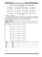
2.1.1 Basic system
Total I/O points
• 10-80 points
Digital I/O module
• 2 modules
A/D-D/A module
• 2 modules
Analog timer
• 3 modules
Maximum
numbers
of expansion
modules
Cnet I/F module
• 1 module
1
Main unit
• K7M-DR10S, K7M-DR20S, K7M-DR30S, K7M-DR40S, K7M-DR60S
K7M-DR10S/DC, K7M-DR20S/DC, K7M-DR30S/DC, K7M-DR40S/DC,
K7M-DR60S/DC, K7M-DT10S, K7M-DT20S, K7M-DT30S, K7M-DT40S,
K7M-DT60S
Digital I/O module
• G7E-DR10A
Analog I/O module
• G7F-ADHA, G7F-AD2A
Expansion
module
Analog timer
• G7F-AT2A
Cnet I/F modules
• G7L-CUEB, G7L-CUEC
DeviceNet I/F module
• G7L-DBEA
FieldBus I/F module
• G7L-FUEA
Items
Communic
ation I/F
module
Profibus I/F Module
• G7L-PBEA
1
Communication modules are not available for 10 points modules (K7M-DR10S, K7M-DR10S/DC, K7M-
DT10S)
main unit
expansion
module
expansion
cable
Total 3 modules
Chapter 2. System Configuration
2-2
2.1.2 Cnet I/F system
Cnet I/F System is used for communication between the main unit and external devices using RS-232C/RS-422 Interface.
The K80S has a built-in RS-232C port and has also G7L-CUEB for RS-232C, G7L-CUEC for RS-422. It is possible to
construct communications systems on demand. (10 points modules include RS-232C and RS-485 ports on the main module,
and no external communication module is available)
1) 1:1 Communications system
(1) 1:1 ratio of an external device (computer) to main unit using a built-in port
(2) 1:1 ratio of an external device (monitoring unit) to main unit using a built-in port
Chapter 2. System Configuration
2-3
(3) RS-232C Communication over a long distance via modem by Cnet I/F modules
2) 1:n Communications system
This method can connect between one computer and multiple main units for up to 32 stations
Modem
Modem
Modem
Modem
G7L-CUEB
G7L-CUEB
G7L-CUEB
RS-232C ⇔ RS-422 Converter
Can be connected Max. 32 stations
G7L-CUEC
G7L-CUEC
K7M-DR10S K7M-DR10S/DC K7M-DT10S
RS-232C ⇔ RS-422
Converter
Chapter 2. System Configuration
2-4
2.2 Product functional model
The following describes functional model of the MASTER-K80Sseries.
2.2.1 Product Function Block
Product function block for the K80Sseries is as follows.
Base Unit
Expansion Modules
Input power Input signal Input signal
Built-in RS-232C I/F Output signal Output signal
Sub-system Description
CPU
• Signal processing function
·Operating system function
·Application program storage / memory function
·Data storage / memory function
·Application program execution function
Input
• The input signals obtained from the machine/process to appropriate signal levels for
processing
Output
• The output signals obtained from the signal processing function to appropriate signal
levels to drive actuators and/or displays
Power Supply
• Provides for conversion and isolation of the PLC system power from the main supply
Communications
Interface
• Provides the data exchange with other systems, such as KGLWIN, computers
Special
/communications
modules
Power
supply
Comm. I/F
Input
Output
Input
Output
CPU
•
DC24V
Power
supply
Chapter 2. System Configuration
2-6
2.2.2 K80S Series System Equipment
Section Items Models Description Remark
K7M-DR10S
K7M-DR10S/DC
K7M-DT10S
• I/O Points
- 6 DC inputs / 4 relay outputs (K7M-DR10S, K7M-DR10S/DC)
- 6 DC inputs / 4 TR outputs (K7M-DT10S)
• Program capacity : 48 kbytes
• Built-in function
-High-speed counter : Phase1 16 kHz, phase2 8 kHz 1channel
-pulse output : 1 × 2 kHz
-pulse catch : pulse width 0.2ms, 4 points
-external contact point interrupt: 0.4ms, 8points
-input filter: 0 ~ 15ms (all input )
-PID control function
-RS-232C communication, RS-485 communication
K7M-DR20S
K7M-DR20S/DC
K7M-DT20S
• I/O Points
- 12 DC inputs / 8 relay outputs (K7M-DR20S, K7M-DR20S/DC)
- 12 DC inputs / 8 TR outputs (K7M-DT20S)
• Program capacity : 48 kbytes
• Built-in function
-High-speed counter : Phase1 16 kHz, phase2 8 kHz 1channel
-pulse output : 1 × 2 kHz
-pulse catch : pulse width 0.2ms, 4 points
-external contact point interrupt: 0.4ms, 8points
-input filter: 0 ~ 15ms (all input )
-PID control function
-RS-232C communication
Basic Base Unit
K7M-DR30S
K7M-DR30S/DC
K7M-DT30S
• I/O Points
- 18 DC inputs / 12 relay outputs (K7M-DR30S, K7M-DR30S/DC)
- 18 DC inputs / 12 TR outputs (K7M-DT30S)
• Program capacity : 48 kbytes
• Built-in function
-High-speed counter : Phase1 16 kHz, phase2 8 kHz 1channel
-pulse output : 1 × 2 kHz
-pulse catch : pulse width 0.2ms, 4 points
-external contact point interrupt: 0.4ms, 8points
-input filter: 0 ~ 15ms (all input )
-PID control function
-RS-232C communication
Chapter 2. System Configuration
2-6
Section Items Models Description Remark
K7M-DR40S
K7M-DR40S/DC
K7M-DT40S
• I/O Points
- 24 DC inputs / 16 relay outputs (K7M-DR40S, K7M-DR40S/DC)
- 24 DC inputs / 16 TR outputs (K7M-DT40S)
• Program capacity : 48 kbytes
• Built-in function
-High-speed counter : Phase1 16 kHz, phase2 8 kHz 1channel
-pulse output : 1 × 2 kHz
-pulse catch : pulse width 0.2ms, 4 points
-external contact point interrupt: 0.4ms, 8points
-input filter: 0 ~ 15ms (all input )
-PID control function
-RS-232C communication
Basic Base Unit
K7M-DR60S
K7M-DR60S/DC
K7M-DT60S
• I/O Points
- 36 DC inputs / 24 relay outputs (K7M-DR60S, K7M-DR60S/DC)
- 36 DC inputs / 24 TR outputs (K7M-DT60S)
• Program capacity : 48 kbytes
• Built-in function
-High-speed counter : Phase1 16 kHz, phase2 8 kHz 1channel
-pulse output : 1 × 2 kHz
-pulse catch : pulse width 0.2ms, 4 points
-external contact point interrupt: 0.4ms, 8points
-input filter: 0 ~ 15ms (all input )
-PID control function
-RS-232C communication
Digital I/O module G7E-DR10A
• I/O points
-6 DC inputs / 4 relay outputs
A/D-D/A
Composite module
G7F-ADHA
• A/D : 2 channel , D/A : 1 channel
A/D conversion
module
G7F-AD2A
• A/D : 4 channel
Analog timer
module
G7F-AT2A
• Points : 4points
• Digital output range : 0~200
G7L-CUEB
• RS-232C : 1 channel
G7L-CUEC
• RS-422 : 1 channel
G7L-DBEA
• DeviceNet I/F module
G7L-FUEA
• FieldBus I/F module
Expansion
module
Communication I/F
module
G7L-PBEA
• Profibus I/F module
Chapter 3. General Specifications
3 -1
Chapter 3. General Specifications
3.1 General specifications
The following shows the general specifications of the MASTER-K series.
No. Item Specifications References
1
Operating ambient
Temperature
0 ~ 55 °C
2
Storage ambient
Temperature
−25 ~ +70 °C
3
Operating ambient
Humidity
5 ~ 95%RH, non-condensing
4
Storage ambient
Humidity
5 ~ 95%RH, non-condensing
Occasional vibration -
Frequency Acceleration Amplitude Sweep count
10 ≤ f < 57Hz
−
0.075mm
57 ≤ f ≤ 150Hz
9.8m/s
2
{1G}
−
Continuous vibration
Frequency Acceleration Amplitude
10 ≤ f < 57Hz
−
0.035mm
5 Vibrations
57 ≤ f ≤ 150Hz
4.9m/s
2
{0.5G}
−
10 times for each X,
Y, Z axis
IEC 61131-2
6 Shocks
• Maximum shock acceleration: 147 m/s
2
{15G}
• Duration time: 11ms
• Pulse wave: half sine pulse ( 3 shocks per axis, on X, Y, Z axis )
IEC 61131-2
Square wave
Impulse noise
± 1,500 V
LGIS’ Internal
Standard
Electronic
discharge
Voltage: 4 kV ( Discharge by contact )
IEC 61131-2,
IEC 1000-4-2
Radiated
electromagnetic
field noise
27 ~ 500 MHz, 10 V/m
IEC 61131-2,
IEC 1000-4-3
Item Power supply
Digital I/O
(>24V)
Digital I/O
(<24V)
Analog I/O
Interface
7 Noise Immunity
Fast transient &
burst noise
Voltage
2kV 1kV 0.25kV
IEC 61131-2
IEC 1000-4-4
8
Atmosphere Free of corrosive gases and excessive dust IEC61131-2
9
Altitude
Up to 2,000m
10
Pollution degree
2
11
Cooling method
Air-cooling
1)
IEC (International Electrotechnical Commission): An international civilian institute who establishes international standards in area of electric
and electronics.
2) Pollution degree: An indicator, which indicates pollution degree, which determine insulation performance of equipment.
Pollution degree 2 : Normally, only non-conductive pollution occurs. Occasionally, however, a temporary conductivity caused by
condensation shall be ex
pected.
REMARK
Chapter 4. Names of Parts
4 -1
Chapter 4. Names of Parts
4.1 Base Unit
No Name
PWR LED
Indicates power supply to the system
y On: When the supply is normal
y Off: When the supply is abnormal
RUN LED
Indicates base unit operation
y On: Indicates local key switch or remote running mode
y Off: with the following led gets off
▶ Without normal power supply to the base unit
▶ While key switch is stopped
▶ Detecting an error makes operation stop
1
CPU
Condition
LED
Indication
ERR LED
Indicates Base Units operation
y On/Off of led: self-inspected error
y Off: CPU is normally working.
2
I/O LED
Indicates I/O operating status
3
Folder for battery
installation
Folder for back-up battery installation
PAU/REM
STOP
RUN
ON
BUILT_INCNET
ROMMODE
OFF
485+
485-
24G
24V
RS-485 (+)
RS-485 (-)
⑩
Chapter 4. Names of Parts
4 -2
No Name
4 Key switch mode creation
Indicates base units drive mode
y RUN: Indicates program operation
y STOP: Stopped program operation
y PAU / REM: usage of each modules are as follows:
▶ PAUSE : temporary stopping program operation
▶ REMOTE : Indicates remote drive
5
Dip-switch memory operation
See Chapter 5
6
RS-232C connector
9-pin DIN connector to connect with external devices like KGLWIN
7
Expansion connector cover
Connector cover to connect with expansion unit
8
Terminal block cover
Protection cover for wiring of terminal block
9
Private hook DIN rail
Private part hook for DIN rail
10 RS-485 communication terminal
Only available with 10 points modules
(K7M-DR10S, K7M-DR10S/DC, K7M-DT10S)
Chapter 4. Names of Parts
4 -3
4.1.1 10-point base unit
4.1.2 20-point base unit
No. Name Usage
1 Terminal block for power supply Terminal blocks for power supply (AC 100V ~ 240V)
2 FG circuit Frame ground
3 Output terminal Output connecting terminal
4 Input terminal Output connecting terminal
5 DC24V, 24G output terminal Service power supply for DC 24V needed place
①
②
③
④
⑤
Chapter 4. Names of Parts
4 -4
4.1.3 30-points base unit
4.1.4 40-points base unit
4.1.5 60-points base unit
Chapter 4. Names of Parts
4 -5
4.2 Expansion Module
4.2.1 Digital I/O Module
4.2.2 A/D・
・・
・D/A Combination Module
No.
Names
①
RUN LED
②
Analog Input Terminal
③
Analog Input (Voltage/current) selecting jumper pin
④
Analog Output Terminal
⑤
External Power Supply Terminal (DC24V)
⑥
Expansion Cable
⑦
Expansion Cable Connecting Terminal
4.2.3 Analog Timer Module
No.
Names
①
RUN LED
②
Analog Timer Volume Control Resistance
③
Expansion Cable
④
Expansion Cable Connecting Terminal
①
②
③
④
⑦
①
②
③
④
⑤
⑥
Chapter 4. Names of Parts
4 -6
4.2.4 Option Modules
Option modules are attached the expansion slot of main unit or expansion unit, and supplies optional functions
such as memory expansion or real time clock. K80S series have two option modules – external memory
module and RTC module.
No. Names
① Optionmodule
② Connector
①
②
Chapter 5 CPU Module
5-1
Chapter 5. CPU
5.1 Specifications
The following table shows the general specifications of the MASTER-K80S series
Specifications
K7M-DR10S K7M-DR20S K7M-DR30S K7M-DR40S K7M-DR60S
K7M-DR10S/DC K7M-DR20S/DC K7M-DR30S/DC K7M-DR40S/DC K7M-DR60S/DC
Item
K7M-DT10S K7M-DT20S K7M-DT30S K7M-DT40S K7M-DT60S
Remarks
Program control method Cycle execution of stored program, Time-driven interrupt, Process-driven interrupt
I/O control method Indirect mode (Refresh method), Direct by program command
Program language Mnemonic, Ladder diagram
Numbers of instructions Basic : 30, Application : 218
Processing speed 0.5µsec/step
Program capacity 7ksteps
I/O points 10 20 30 40 60
P P000 ~ P13F I/O relay
M M000 ~ M191F (3,072points) Auxiliary relay
K K000 ~ K31F (512 points) Keep relay
L L000 ~ L63F (1,024 points) Link relay
F F000 ~ F63F (1,024 points) Special relay
T
100msec : T000 ~ T191 (192 points)
10msec : T192 ~ T255 (64 points)
Timer
C C000 ~ C255 (256 points) Counter
S S00.00 ~ S99.99 (100×100 steps) Step controller
Memory
device
D D0000 ~ D4999 (5,000 words) Data register
Operation modes RUN, STOP, PAUSE, DEBUG
Self-diagnosis functions Detect errors of scan time, memory, I/O, battery, and power supply
Data back-up method Battery-back-up
Max. expansion level Up to 3 level
Chapter 5 CPU Module
5-2
Item Specifications Remarks
PID control function Function block control, auto tuning, forced output, adjustable operation
scan time, forward/reverse operation control
Cnet I/F Function Master-K exclusive protocol support
MODBUS protocol support
User’s protocol support
Common use with
KGLWIN port
Capacity 1 phase : 16 kHz, 1 channel
2 phase : 8 kHz,1 channel
Counter function It has 3diffferant counter function as following;
1 phase, up/down by program
1 phase, up/down by B phase input
2 phase, up/down by phase difference
Multiplication
function
Multiplication : 1, 2, or 4 (adjustable)
High-
speed
counter
Data comparison
function
Execute a task program when the elapsed counter value reaches to the
preset value
Pulse catch Minimum pulse width : 0.2msec, 8 points
Pulse output 2khz, 1point Transistor output only
Internal
Function
External interrupt 8points, 0.4ms
Input filter 0~15ms
K7M-DR10S 370
K7M-DR20S 530
K7M-DR30S 550
K7M-DR40S 670
K7M-DR60S 845
K7M-DR10S/DC 370
K7M-DR20S/DC 530
K7M-DR30S/DC 550
K7M-DR40S/DC 670
K7M-DR60S/DC 845
K7M-DT10S 370
K7M-DT20S 540
K7M-DT30S 550
K7M-DT40S 670
K7M-DT60S 845
Weight (g)
G7E-DR10A 230