Controlled-Potential Techniques
Bạn đang xem bản rút gọn của tài liệu. Xem và tải ngay bản đầy đủ của tài liệu tại đây (357.18 KB, 48 trang )
3
CONTROLLED-POTENTIAL
TECHNIQUES
The basis of all controlled-potential techniques is the measurement of the
current response to an applied potential. A multitude of potential excitations
(including a ramp, potential steps, pulse trains, a sine wave, and various combinations thereof) exists. The present chapter reviews those techniques that
are widely used.
3.1
CHRONOAMPEROMETRY
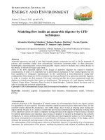
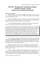
Chronoamperometry involves stepping the potential of the working electrode
from a value at which no faradaic reaction occurs to a potential at which the
surface concentration of the electroactive species is effectively zero (Fig. 3.1a).
A stationary working electrode and unstirred (quiescent) solution are used.
The resulting current–time dependence is monitored. As mass transport under
these conditions is solely by diffusion, the current–time curve reflects the
change in the concentration gradient in the vicinity of the surface (recall
Section 1.2). This involves a gradual expansion of the diffusion layer associated with the depletion of the reactant, and hence decreased slope of the concentration profile as time progresses (see Fig. 3.1b). Accordingly, the current
(at a planar electrode) decays with time (Fig. 3.1c), as given by the Cottrell
equation
Analytical Electrochemistry, Third Edition, by Joseph Wang
Copyright © 2006 John Wiley & Sons, Inc.
67
68
CONTROLLED-POTENTIAL TECHNIQUES
E
E2
E1
(a)
0
Time
Concentration
C0
Increasing
time
(b)
0
Distance (x)
icat
(c)
0
Time
Figure 3.1 Chronoamperometric experiment: (a) potential–time waveform; (b)
change in concentration profiles as time progresses; (c) the resulting current–time
response.
i(t ) =
nFACD1 2
= kt −1 2
π1 2t 1 2
(3.1)
where n, F, A, C, D, and t are the number of electrons, Faraday’s constant, the
surface area, the concentration, the diffusion coefficient, and time, respectively.
Such an it1/2 constancy is often termed a “Cottrell behavior.” Deviations from
such behavior occur at long times (usually over 100 s) as a result of natural
69
POLAROGRAPHY
convection effects, due to coupled chemical reactions, and when using nonplanar electrodes or microelectrodes with high perimeter : area ratio (see
Section 4.5.4). In the latter case, a time-independent current (proportional to
the concentration) is obtained for t > 0.1 s, due to a large radial diffusion contribution. Similar considerations apply to spherical electrodes whose current
response following potential step contains time-dependent and timeindependent terms [Eq. (1.12)]. Recall also that for short values of t (t < 50 ms),
the chronoamperometric signal contains an additional background contribution of the charging current [Eq. (1.49)]. This exponentially decaying charging
current represents the main contribution to the response in the absence of an
electroactive species.
Chronoamperometry is often used for measuring the diffusion coefficient
of electroactive species or the surface area of the working electrode. Some
analytical applications of chronoamperometry (e.g., in vivo bioanalysis) rely
on pulsing of the potential of the working electrode repetitively at fixed time
intervals. Some popular test strips for blood glucose (discussed in Chapter 6)
involve potential-step measurements of an enzymatically liberated product (in
connection with a preceding incubation reaction). Chronoamperometry can
also be applied to the study of mechanisms of electrode processes. Particularly
attractive for this task are reversal double-step chronoamperometric experiments (where the second step is used to probe the fate of a species generated
in the first one).
The potential-step experiment can also be used to record the charge–time
dependence. This is accomplished by integrating the current resulting from the
potential step and adding corrections for the charge due to the double-layer
charging (Qdl) and reaction of the adsorbed species (Qi):
Q=
2 nFACD1 2t 1 2
+ Qdl + Qi
π1 2
(3.2)
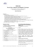
Such a charge measurement procedure, known as chronocoulometry, is particularly useful for measuring the quantity of adsorbed reactants (because of
the ability to separate the charges produced by the adsorbed and solution
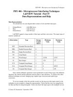
species). A plot of the charge (Q) versus t1/2, known as an Anson plot, yields
an intercept at t = 0 that corresponds to the sum of Qdl and Qi (Fig. 3.2). The
former can be estimated by subtracting the intercept obtained in an identical
experiment carried out in the blank solution.
3.2
POLAROGRAPHY
Polarography is a subclass of voltammetry in which the working electrode is
dropping mercury. Because of the special properties of this electrode, particularly its renewable surface and wide cathodic potential range (see Chapters
3–5 for details), polarography has been widely used for the determination of
70
CONTROLLED-POTENTIAL TECHNIQUES
Q (mC)
2.0
Qtotal
1.0
Qi
Qdl
0
0
1
2
3
4
5
6
7
8
9
t1/2 (ms1/2)
Figure 3.2
Chronocoulometric experiment: Anson plot of Q versus t1/2.
many important reducible species. This classical technique was invented by J.
Heyrovsky in Czechoslovakia in 1922, and had an enormous impact on the
progress of electroanalysis (through many subsequent developments).
Accordingly, Heyrovsky was awarded the 1959 Noble Prize in Chemistry.
The excitation signal used in conventional (DC) polarography is a linearly
increasing potential ramp. For a reduction, the initial potential is selected to
ensure that the reaction of interest does not take place. The potential is then
scanned cathodically while the current is measured. Such current is proportional to the slope of the concentration–distance profile (see Section 1.2.1.2).
At a sufficiently negative potential, reduction of the analyte commences, the
concentration gradient increases, and the current rises rapidly to its limiting
(diffusion-controlled) value. At this plateau, any analyte particle that arrives
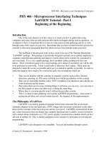
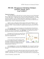
at the electrode surface instantaneously undergoes an electron transfer reaction, and the maximum rate of diffusion is achieved. The resulting polarographic wave is shown in Figure 3.3. The current oscillations reflect the growth
and fall of the individual drops.
71
POLAROGRAPHY
20
Current (mA)
B
10
id
A
0
E1/2
0
–0.6
–1.2
Potential (V)
Figure 3.3 Polarograms for 1 M hydrochloric acid (A) and 4 × 10⁻⁴ M Cd2+ in 1 M
hydrochloric acid (B); id represents the limiting current, while E1/2 is the half-wave
potential.
To derive the expression for the current response, one must account for the
variation of the drop area with time
A = 4π
3mt
4 πd
2 3
= 0.85( mt )
2 3
(3.3)
where t is the time and m and d are the mass flow rate and density of mercury,
respectively. By substituting the surface area [from Eq. (3.3)] into the Cottrell
equation [Eq. (3.1)], and replacing D by 7/3D (to account for the compression
of the diffusion layer by the expanding drop), we can obtain the Ilkovic equation for the limiting diffusion current (1):
id = 708 nD1 2 m 2 3t 1 6C
(3.4)
Here, id will have units of amperes (A), when D is in cm2/s, m is in g/s, t is in
seconds, and C is in mol/cm3. This expression represents the current at the end
of the drop life. The average current over the drop life is obtained by integrating the current of this time period:
iav = 607 nD1 2 m 2 3t 1 6C
(3.5)
72
CONTROLLED-POTENTIAL TECHNIQUES
To determine the diffusion current, it is necessary to subtract the residual
current. This can be achieved by extrapolating the residual current prior to the
wave or by recording the response of the deaerated supporting electrolyte
(blank) solution. Standard addition or a calibration curve is often used for
quantitation. Polarograms to be compared for this purpose must be recorded
in the same way.
The potential where the current is one-half of its limiting value is called the
half-wave potential, E1/2. The half-wave potential (for electrochemically
reversible couples) is related to the formal potential E° of the electroactive
species according to
E1 2 = E ° +
1 2
RT
log( DR DO )
nF
(3.6)
where DR and DO are the diffusion coefficients of the reduced and oxidized
forms of the electroactive species, respectively. Because of the similarity in the
diffusion coefficients, the half-wave potential is usually similar to the formal
potential. Thus, the half-wave potential, which is a characteristic of a particular species in a given supporting electrolyte solution, is independent of the
concentration of that species. Therefore, by measuring the half-wave potential, one can identify the species responsible for an unknown polarographic
wave. Typical half-wave potentials for several reducible organic functionalities, common in organic compounds, are given in Table 3.1. Compounds containing these functionalities are ideal candidates for polarographic
measurements. (Additional oxidizable compounds can be measured using
solid–electrode voltammetric protocols.) Since neutral compounds are
involved, such organic polarographic reductions commonly involve hydrogen
ions. Such reactions can be represented as
TABLE 3.1
Functional Groups Reducible at the DME
Class of
Compounds
Azo
Carbon–carbon double bondb
Carbon–carbon triple bondb
Carbonyl
Disulfide
Nitro
Organic halides
Quinone
a
b
Functional
E1/2 (Va)
Group
—N==N—
—C==C—
—C≡C—
C==O
S—S
NO2
C—X (X = Br, Cl, I)
C==O
−0.4
−2.3
−2.3
−2.2
−0.3
−0.9
−1.5
−0.1
Against the saturated calomel electrode at pH = 7.
Conjugated with a similar bond or with an aromatic ring.
73
POLAROGRAPHY
R + nH + + ne − ∫ RH n
(3.7)
where R and RHn are oxidized and reduced forms of the organic molecule.
For such processes, the half-wave potential will be a function of pH (with
a negative shift of about 59 mV/n for each unit increase in pH, due to
decreasing availability of protons). Thus, in organic polarography, good buffering is vital for generating reproducible results. Reactions of organic compounds are also often slower and more complex than those for inorganic
cations.
For the reduction of metal complexes, the half-wave potential is shifted to
more negative potentials, reflecting the additional energy required for the
complex decomposition. Consider the reversible reduction of a hypothetical
metal complex, MLp:
ML p + ne − + Hg ∫ M(Hg) + pL
(3.8)
where L is the free ligand and p is the stoichiometric number. (The charges
are omitted for simplicity.) The difference between the half-wave potential for
the complexed and uncomplexed metal ion is given by (2)
(E1 2 )c − (E1 2 ) free =
RT
RT
RT D free
p ln[L] +
ln Kd −
ln
nF
nF
nF Dc
1 2
(3.9)
where Kd is the formation constant. The stoichiometric number can thus be
computed from the slope of a plot (E1/2)c versus ln [L]. It is possible to exploit
Eq. (3.9) to improve the resolution between two neighboring polarographic
waves, based on a careful choice of the ligand and its concentration.
For reversible systems (with fast electron transfer kinetics), the shape of the
polarographic wave can be described by the Heyrovsky–Ilkovic equation:
E = E1 2 +
RT i d − i
ln
nF i
(3.10)
It follows from this equation that a plot of E versus log [(id − i)/i] should yield
a straight line with a slope of 0.059/n at 25°C. Such a plot offers a convenient
method for the determination of n. In addition, the intercept of this line will
be the half-wave potential. Another way to estimate n is to measure (E3/4 −
E1/4), which corresponds to 56.4/n mV for a reversible system (E3/4 and E1/4 are
the potentials for which i = 0.75id and i = 0.25id, respectively). It should be
emphasized that many polarographic processes, especially those of organic
compounds, are not reversible. For those that depart from reversibility, the
wave is “drawn out,” with the current not rising steeply, as is shown in Figure
3.3. The shape of the polarographic response for an irreversible reduction
process is given by
74
CONTROLLED-POTENTIAL TECHNIQUES
1 2
RT
id − i t
ln 1.35kf
E = E° +
i D
αnF
(3.11)
where α is the transfer coefficient and kf is the rate constant of the forward
reaction.
In a few instances, the polarographic wave is accompanied by a large peak
(where the current rises to a maximum before returning to the expected diffusion current plateau). Such an undesired peak, known as the polarographic
maximum, is attributed to a hydrodynamic flow of the solution around the
expanding mercury drop, can be suppressed by adding a small amount of a
surface-active material (such as Triton X-100).
When the sample solution contains more than one reducible species,
diffusion currents resulting from each of them are observed. The heights
of the successive waves can be used to measure the individual analytes,
provided there is a reasonable difference (>0.2 V) between the half-wave
potentials. The baseline for measuring the limiting current of the second
species is obtained by extrapolation of the limiting current of the first process.
With a potential window of ~2 V, five to seven individual polarographic
waves could be observed. Solution parameters, such as the pH or concentration of complexing agents, can be manipulated to deliberately shift the peak
potential and hence to improve the resolution of two successive waves.
Successive waves are also observed for samples containing a single analyte
that undergoes reduction in two or more steps (e.g., 1,4-benzodiazepine,
tetracycline).
The background (residual) current that flows in the absence of the electroactive species of interest is composed of contributions due to double-layer
charging process and redox reactions of impurities, as well as of the solvent,
electrolyte, or electrode. The latter processes (e.g., hydrogen evolution and
mercury oxidation) are those that limit the working potential range. In acidic
solutions, the negative background limit shifts by approximately 59 mV per
each pH unit to more positive potentials with decreasing pH. Within the
working potential window, the charging current is the major component of the
background (which limits the detection limit). It is the current required to
charge the electrode–solution interface (which acts as a capacitor) on changing the potential or the electrode area (see Section 1.3). Thus, the charging
current is present in all conventional polarographic experiments, regardless of
the purity of reagents. Because of the negligible potential change during the
drop life, the charging associated with the potential scan can be ignored. The
value of the polarographic charging current thus depends on the time change
of the electrode area:
ic =
dq
dA
= (E − Epzc )Cdl
dt
dt
(3.12)
75
POLAROGRAPHY
By substituting the derivative of the area with time [from Eq. (3.2)], one
obtains
ic = 0.00567(E − Epzc )Cdl m 2 3t −1 3
(3.13)
Hence, the charging current decreases during the drop life, while the diffusion
current increases (Fig. 3.4):
itotal (t ) = id (t ) + ic (t ) = kt 1 6 + k ′t −1 3
(3.14)
The analytical significance of the charging current depends on how large it is
relative to the diffusion current of interest. When the analyte concentration is
in the 10−4–10−2 M range, the current is mostly faradaic, and a well-defined
polarographic wave is obtained. However, at low concentrations of the analyte,
the charging current contribution becomes comparable to the analytical signal,
and the measurement becomes impossible. The charging current thus limits
the detection limit of classical polarography to the 5 × 10⁻⁶–1 × 10⁻⁵ M region.
Lower detection limits are obtained for analytes with redox potentials closer
to Epzc [when ic approaches its smaller value, Eq. (3.12)]. Advanced (pulse)
polarographic techniques, discussed in Section 3.3, offer lower detection limits
by taking advantage of the different time dependences of the analytical and
charging currents [Eq. (3.14)]. Such developments have led to a decrease in
the utility of DC polarography.
B
i
A
0
1
2
t /td
Figure 3.4 Variation of the charging and diffusion currents (A and B, respectively)
during the lifetime of a drop.
76
3.3
CONTROLLED-POTENTIAL TECHNIQUES
PULSE VOLTAMMETRY
Pulse voltammetric techniques, introduced by Barker and Jenkin (3), are
aimed at lowering the detection limits of voltammetric measurements. By substantially increasing the ratio between the faradaic and nonfaradaic currents,
such techniques permit convenient quantitation down to the 10−8 M concentration level. Because of their greatly improved performance, modern pulse
techniques have largely supplanted classical polarography in the analytical
laboratory. The various pulse techniques are all based on a sampled
current/potential-step (chronoamperometric) experiment. A sequence of such
potential steps, each with a duration of about 50 ms, is applied onto the
working electrode. After the potential is stepped, the charging current decays
rapidly (exponentially) to a negligible value, while the faradaic current decays
more slowly. Thus, by sampling the current late in the pulse life, an effective
discrimination against the charging current is achieved.
The difference between the various pulse voltammetric techniques is the
excitation waveform and the current sampling regime. With both normal-pulse
and differential-pulse voltammetry, one potential pulse is applied for each
drop of mercury when the DME is used. (Both techniques can also be used at
solid electrodes.) By controlling the drop time (with a mechanical knocker),
the pulse is synchronized with the maximum growth of the mercury drop. At
this point, near the end of the drop lifetime, the faradaic current reaches its
maximum value, while the contribution of the charging current is minimal
(based on the time dependence of the components).
3.3.1
Normal-Pulse Voltammetry
Potential
Normal-pulse voltammetry consists of a series of pulses of increasing amplitude applied to successive drops at a preselected time near the end of each
drop lifetime (4). Such a normal pulse train is shown in Figure 3.5. Between
16.7 ms
50
ms
Ein
Drop fall
Figure 3.5
Time
Excitation signal for normal-pulse voltammetry.
77
PULSE VOLTAMMETRY
the pulses, the electrode is kept at a constant (base) potential at which no
reaction of the analyte occurs. The amplitude of the pulse increases linearly
with each drop. The current is measured about 40 ms after the pulse is applied,
at which time the contribution of the charging current is nearly zero. In
addition, because of the short pulse duration, the diffusion layer is thinner
than that of DC polarography (i.e., greater flux of analyte) and hence
the faradaic current is increased. The resulting voltammogram has a
sigmoidal shape, with a limiting current given by a modified Cottrell
equation:
il =
nFAD1 2C
πt m
(3.15)
where tm is the time after application of the pulse where the current is sampled.
This current can be compared to that measured in DC polarography:
il,NP 3t d
=
il,dc 7t m
1 2
(3.16)
This ratio predicts that normal-pulse polarography will be 5–10 times more
sensitive than DC polarography (for typical values of td and tm). Normal-pulse
polarography may be advantageous also when using solid electrodes. In particular, by maintaining a low initial potential during most of the operation, it
is possible to alleviate surface fouling problems (due to adsorbed reaction
products).
A related technique, reverse-pulse voltammetry, has a pulse sequence
that is a mirror image of that of normal-pulse voltammetry (5). In this
case, the initial potential is on the plateau of the wave (i.e., where reduction
occurs), and a series of positive-going pulses of decreasing amplitude is
applied.
3.3.2
Differential-Pulse Voltammetry
Differential-pulse voltammetry is an extremely useful technique for measuring trace levels of organic and inorganic species. In differential-pulse voltammetry, fixed magnitude pulses—superimposed on a linear potential ramp—are
applied to the working electrode at a time just before the end of the drop (Fig.
3.6). The current is sampled twice, just before the pulse application (at 1) and
again late in the pulse life (after ~40 ms, at 2, when the charging current has
decayed). The first current is instrumentally subtracted from the second, and
this current difference [∆i = i(t2) − i(t1)] is plotted against the applied potential. The resulting differential-pulse voltammogram consists of current peaks,
the height of which is directly proportional to the concentration of the corresponding analytes:
78
CONTROLLED-POTENTIAL TECHNIQUES
E
50 ms
0.5–0.5 s
DE
2
1
Time
Figure 3.6
Excitation signal for differential-pulse voltammetry.
ip =
nFAD1 2C 1 − σ
1+ σ
πt m
(3.17)
where σ = exp[(nf/RT)(∆E/2)] (∆E is the pulse amplitude). The maximum
value of the quotient (1 − σ)/(1+ σ), obtained for large pulse amplitudes, is
unity (6).
The peak potential (Ep) can be used to identify the species, as it occurs near
the polarographic half-wave potential:
Ep = E1 2 − ∆ E 2
(3.18)
The differential-pulse operation results in a very effective correction of the
charging background current. The charging-current contribution to the differential current is negligible, as described by
∆ic ~ − 0.00567C i ∆Em 2 3t −1 3
(3.19)
where Ci is the integral capacitance. Such background contribution is smaller
by more than an order of magnitude than the charging current of normal-pulse
voltammetry. Accordingly, differential-pulse voltammetry allows measurements at concentrations as low as 10−8 M (about 1 µg/L). The improved
detectability over DC polarography is demonstrated in Figure 3.7, which compares the response of both techniques for the antibiotic chloramphenicol
present at the 1.3 × 10⁻⁵ M level. Similarly, the improvements over normalpulse polarography are illustrated in Figure 3.8.
The peak-shaped response of differential-pulse measurements results also
in improved resolution between two species with similar redox potentials. In
various situations, peaks separated by 50 mV may be measured. Such quantitation depends not only on the corresponding peak potentials but also on the
widths of the peak. The width of the peak (at half-height) is related to the electron stoichiometry:
79
PULSE VOLTAMMETRY
Signal
(a)
100 nA
0 –0.1 –0.2 –0.3 –0.4 –0.5 –0.6 –0.7 –0.8 –0.9 –1.0 –1.1 –1.2 –1.3 –1.4 –1.5
Potential (V vs. SCE)
Signal
(b)
100 nA
0 –0.1 –0.2 –0.3 –0.4 –0.5 –0.6 –0.7 –0.8 –0.9 –1.0 –1.1 –1.2 –1.3 –1.4 –1.5
Potential (V vs. SCE)
Figure 3.7 Differential-pulse (a) and DC (b) polarograms for a 1.3 × 10⁻⁵ M chloramphenicol solution. (Reproduced with permission from Ref. 7.)
W1 2 =
3.52RT
nF
(3.20)
and thus corresponds to 30.1 mV for n = 1 (at 25°C). The peak-shaped
response, coupled with the flat background current, makes the technique particularly useful for analysis of mixtures.
The selection of the pulse amplitude and potential scan rate usually requires
a tradeoff among sensitivity, resolution, and speed. For example, larger pulse
amplitudes result in larger and broader peaks. Pulse amplitudes of 25–50 mV,
80
Current
CONTROLLED-POTENTIAL TECHNIQUES
B
A
Potential
Figure 3.8 Normal-pulse (curve A) and differential-pulse (curve B) polarograms for
a mixture of 1 mg/L cadmium and lead ions. Electrolyte, 0.1 M HNO3.
coupled with a scan rate of 5 mV/s, are commonly employed. Irreversible redox
systems result in lower and broader current peaks (i.e., inferior sensitivity and
resolution) compared with those predicted for reversible systems (6). In addition to improvements in sensitivity and resolution, the technique can provide
information about the chemical form in which the analyte appears (oxidation
states, complexation, etc.).
3.3.3
Square-Wave Voltammetry
Square-wave voltammetry is a large-amplitude differential technique in which
a waveform composed of a symmetric square wave, superimposed on a base
staircase potential, is applied to the working electrode (8) (Fig. 3.9). The
current is sampled twice during each square-wave cycle, once at the end of the
forward pulse (at t1) and once at the end of the reverse pulse (at t2). Since
the square-wave modulation amplitude is very large, the reverse pulses cause
the reverse reaction of the product (of the forward pulse). The difference
between the two measurements is plotted versus the base staircase potential.
81
Potential
PULSE VOLTAMMETRY
1
Esw
DE
2
τ
Td
Time
Figure 3.9 Square-wave waveform showing the amplitude Esw, step height ∆E, squarewave period T, delay time Td, and current measurement times 1 and 2. (Reproduced
with permission from Ref. 9.)
A dimensionless plot of the theoretical forward, reverse, and difference currents is given in Figure 3.10 for a rapid reversible redox system. The resulting
peak-shaped voltammogram is symmetric about the half-wave potential, and
the peak current is proportional to the concentration. Excellent sensitivity
accrues from the fact that the net current is larger than either the forward or
reverse components (since it is the difference between them); the sensitivity is
higher than that of differential pulse polarography (in which the reverse current
is not used). Coupled with the effective discrimination against the charging
background current, very low detection limits near 1 × 10⁻⁸ M can be attained.
Comparison between square-wave and differential-pulse voltammetry for
reversible and irreversible cases indicated that the square-wave currents are
4 and 3.3 times higher, respectively, than the analogous differential-pulse
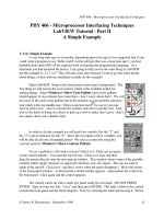
response (10). Figure 3.11 displays typical square-wave voltammograms
obtained at a printed carbon strip electrode for increasing concentrations
(1–10 ppm) of the nitroaromatic explosive 2,4,6-trinitrotoluene (TNT) (11).
The major advantage of square-wave voltammetry is its speed. The effective scan rate is given by f ∆Es. The term f is the square-wave frequency (in
Hz) and ∆Es is the step height. Frequencies of 1–100 cycles per second permit
the use of extremely fast potential scan rates. For example, if ∆Es = 10 mV and
f = 50 Hz, then the effective scan rate is 0.5 V/s. As a result, the analysis time
is drastically reduced; a complete voltammogram can be recorded within a few
82
CONTROLLED-POTENTIAL TECHNIQUES
15
C
10
ψ
A
5
0
B
–5
200
100
0
–100
–200
–300
–400
–500
n(E – E1/2) mV
Figure 3.10 Square-wave voltammograms for reversible electron transfer: (curve A)
forward current; (curve B) reverse current; (curve C) net current. (Reproduced with
permission from Ref. 9.)
seconds, as compared with about 2–3 min in differential-pulse voltammetry.
Because of the fast scan rates, the entire voltammogram is recorded on a single
mercury drop. Hence, such an operation consumes many drops (compared to
other pulse techniques). The inherent speed of square-wave voltammetry can
greatly increase sample throughputs in batch (12) and flow (13) analytical
operations. In addition, square-wave voltammetric detection for liquid chromatography and capillary electrophoresis can be used to resolve coeluting or
comigrating species and assist in peak identification (14, 15). Kinetic studies
can also benefit from the rapid scanning capability and the reversal nature of
square-wave voltammetry.
3.3.4
Staircase Voltammetry
Staircase voltammetry has been proposed as a useful tool for rejecting the
background charging current. The potential–time waveform involves successive potential steps of ~10 mV height and about 50 ms duration (Fig. 3.12). The
current is sampled at the end of each step, where the charging current has
decayed to a negligible value. Hence, this waveform couples the discrimination against the charging current with the experimental speed of linear scan
voltammetry. Such an operation results in a peak-shaped current response,
similar to that of linear scan experiments. Indeed, as the steps become smaller,
83
PULSE VOLTAMMETRY
0
a
1.0
b
d
e
50
40
3.0
Current (à)
Current (1ì 106 A)
c
2.0
4.0
f
g
30
h
20
i
j
10
5.0
k
0
0
2
4
6
8 10
Concentration (ppm)
12
6.0
0
0.10
0.20
0.30 0.40
Potential (V)
0.50
0.60 –0.70
Potential
Figure 3.11 Square-wave voltammograms for TNT solutions of increasing concentration from 1 to 10 ppm (curves b–k), along with the background voltammogram
(curve a) and resulting calibration plot (inset). (Reproduced with permission from Ref.
11.)
S
tp
S
DEs
S
S
S
Time
Figure 3.12 Potential–time waveform used in staircase voltammetry.
the equations for the staircase voltammetric response converge with those of
linear scan voltammetry (16). As such, staircase voltammetry can be considered as the digital version of linear scan voltammetry. Similarly, cyclic staircase voltammetric experiments, in which the direction of the potential steps is
reversed at a switching potential, result in a voltammetric response resembling
cyclic voltammetry (but with a much reduced charging-current contribution).
84
3.4
CONTROLLED-POTENTIAL TECHNIQUES
AC VOLTAMMETRY
Alternating current (AC) voltammetry is a frequency-domain technique which
involves the superimposition of a small amplitude AC voltage on a linear ramp
(Fig. 3.13). Usually the alternating potential has a frequency of 50–100 Hz and
an amplitude of 10–20 mV. The AC signal thus causes a perturbation in the
surface concentration, around the concentration maintained by the DC potential ramp. The resulting AC current is plotted against the potential. Such a
voltammogram shows a peak, the potential of which is the same as that of the
polarographic half-wave potential. (At this region the sinusoid has maximum
impact on the surface concentration, i.e., on the current.) For a reversible
system, such a response is actually the derivative of the DC polarographic
response. The height of the AC voltammetric peak is proportional to the concentration of the analyte and, for a reversible reaction, to the square root of
the frequency (ω):
ip =
n 2 F 2 Aω 1 2 D1 2C∆E
4RT
(3.21)
Potential
The term ∆E is the amplitude. The peak width is independent of the AC frequency, and is 90.4/n mV (at 25°C).
The detection of the ac component allows one to separate the contributions
of the faradaic and charging currents. The former is phase-shifted by 45° relative to the applied sinusoidal potential, while the background component is
90° out of phase. The charging current is thus rejected using a phase-sensitive
lock-in amplifier (able to separate the in-phase and out-of-phase current components). As a result, reversible electrode reactions yield a detection limit of
~5 × 10⁻⁷ M.
Time
Figure 3.13 Potential-time waveform used in alternating current (ac) voltammetry.
STRIPPING ANALYSIS
85
Substantial loss in sensitivity is expected for analytes with slow electron
transfer kinetics. This may be advantageous for measurements of species with
fast electron transfer kinetics in the presence of one (e.g., dissolved oxygen)
that is irreversible. (For the same reason, the technique is very useful for the
study of electron processes.) Theoretical discussions on AC voltammetry are
available in the literature (17–19).
Large-amplitude sine waves have been combined with conversion of the
raw time domain (from the electrochemical cell) into the frequency domain
(20,21). Such frequency-based sinusoidal voltammetry offers decoupling of the
faradaic signal from the background components (i.e., lower detection limits),
as well as generation of a distinct “fingerprint” frequency spectrum to aid in
the identification of specific chemical molecules (20). Such decoupling of the
faradaic signal reflects the fact that at large (i.e., >50 mV) amplitudes of the
applied potential, it exhibits an intensity at higher order harmonics of the fundamental excitation frequency, as compared to the capacitive charging current
that remains at the fundamental frequency. In addition to improved sensitivity at higher harmonics, redox species with different electrochemical properties can be detected selectively on the basis of their unique “fingerprint”
frequency response (20,22). For example, measurements in the presence of dissolved oxygen have been accomplished on the basis of kinetic discrimination
against the oxygen reduction process (22).
3.5
STRIPPING ANALYSIS
Stripping analysis is an extremely sensitive electrochemical technique for
measuring trace metals (23,24). Its remarkable sensitivity is attributed to the
combination of an effective preconcentration step with advanced measurement procedures that generates an extremely favorable signal : background
ratio. Since the metals are preconcentrated into the electrode by factors of
100–1000, detection limits are lowered by two to three orders of magnitude
compared to solution-phase voltammetric measurements. Hence, four to six
metals can be measured simultaneously in various matrices at concentration
levels down to 10−10 M, utilizing relatively inexpensive instrumentation. The
ability to obtain such low detection limits strongly depends on the degree to
which contamination can be minimized. Expertise in ultratrace chemistry is
required.
Essentially, stripping analysis is a two-step technique. The first, or deposition step, involves the electrolytic deposition of a small portion of the metal
ions in solution into the mercury electrode to preconcentrate the metals. This
is followed by the stripping step (the measurement step), which involves the
dissolution (stripping) of the deposit. Different versions of stripping analysis
can be employed, depending on the nature of the deposition and measurement steps.
86
3.5.1
CONTROLLED-POTENTIAL TECHNIQUES
Anodic Stripping Voltammetry
Anodic stripping voltammetry (ASV) is the most widely used form of stripping analysis. In this case, the metals are being preconcentrated by electrodeposition into a small-volume mercury electrode (a thin mercury film or a
hanging mercury drop). The preconcentration is done by cathodic deposition
at a controlled time and potential. The deposition potential is usually 0.3–0.5
V more negative than E° for the least easily reduced metal ion to be determined. The metal ions reach the mercury electrode by diffusion and convection, where they are reduced and concentrated as amalgams:
M n + + ne − + Hg → M(Hg)
(3.22)
The convective transport is achieved by electrode rotation or solution stirring (in conjunction with the mercury film electrode) or by solution stirring
(when using the hanging mercury drop electrode). Quiescent solutions can be
used when using mercury ultramicroelectrodes. The duration of the deposition
step is selected according to the concentration level of the metal ions in question, from less than 0.5 min at the 10−7 M level to about 20 min at the 10−10 M
level. The concentration of the metal in the amalgam, CHg, is given by Faraday’s
law
C Hg =
il t d
nFVHg
(3.23)
where il is the limiting current for the deposition of the metal, td is the length
of the deposition period, and VHg is the volume of the mercury electrode. The
deposition current is related to the flux of the metal ion at the surface. The
total amount of metal plated represents a small (and yet reproducible) fraction of the metal present in the bulk solution.
Following the preselected time of the deposition, the forced convection is
stopped, and the potential is scanned anodically, linearly, or in a more sensitive potential–time (pulse) waveform that discriminates against the charging
background current (usually square-wave or differential-pulse ramps). Such
pulse excitations also offer reduced oxygen interferences and analyte replating, respectively. During this anodic scan, the amalgamated metals are reoxidized, stripped out of the electrode (in an order that is a function of each metal
standard potential), and an oxidation (stripping) current is flowing:
M(Hg) → M n + + ne − + Hg
(3.24)
Repetitive ASV runs can be performed with good reproducibility in connection to a short (30–60-s) “electrochemical cleaning” period at the final potential (e.g., +0.1 V using mercury electrodes). The potential–time sequence used
in ASV, along with the resulting stripping voltammogram, is shown in Figure