Scenarios
Bạn đang xem bản rút gọn của tài liệu. Xem và tải ngay bản đầy đủ của tài liệu tại đây (1.46 MB, 49 trang )
12
Scenarios
This chapter applies the acquired knowledge base of the previous chapters to
describe the various GSM subsystems via signaling protocols. Every presented
scenario is explained in detail.
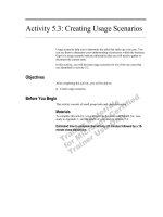
Before presenting those details, however, the commonality, or “red
thread” of the scenarios should be emphasized. For that purpose, the block dia-
gram in Figure 12.1 applies to all: MOC (mobile originating call), MTC
(mobile terminating call), and LU (location update). The following is an expla-
nation of the individual blocks in Figure 12.1:
•
Only in a MTC does the network search for a particular subscriber
(paging).
•
When the MS is located or when the MS initiates a call, a control
channel between MS and BSC has to be established.
•
The MS uses the control channel for identification and indicates to the
BSC in detail which service is requested.
•
The BSC passes the service request of the MS to the NSS. For that
purpose, the BSS has to request an SCCP connection from the MSC.
•
The NSS reacts on a connection request of any kind with a request for
authentication (except for an emergency call). Additionally, the IMEI
may be checked.
•
Ciphering between BTS and MS is activated in successful authentica-
tion. Ciphering prevents tapping into the Air-interface.
•
Additional information between MS and NSS are exchanged after
activation of ciphering. The additional information either terminates
225
a successful LU, or, in case of a connection request, defines the details
of that connection (e.g., directory number of the called subscriber,
required technical capabilities of the network and the MS). The
process is synchronized between MS and NSS.
•
The assignment of the TCH on the A-interface and Air-interface is
done separately, except in the case of off-air call setup (OACSU). Up
to this point, the communication has been done via a control channel.
226 GSM Networks: Protocols, Terminology, and Implementation
Air-interface Abis-interface A-interface
Agreement about the type of connection, identification
Phase of active call/exchange of payload
BTS
TRX
MSC
VLR
BSC
Search for the subscriber (paging)
Request for assignment of a control cannel
Authentication, authorization, IMEI check
Activation of ciphering
Exchange of signaling information (called party, LOC_UPD_ACC, ...)
Traffic channel assignment (Air-interface)
TCH assignment
(A-Interface)
Call is through connected, ring tone, ringing
Both parties are connected
(One) party releases the call
Channel release (Air-interface)
Channel release
SCCP/A channel
Figure 12.1 Block diagram of the base scenarios.
•
The system waits, after assignment of the traffic channel, until
an end-to-end connection is in place. At the end of this phase, the
telephone on one side rings, and the other side hears the ring-
back tone.
•
When the called subscriber takes the call, the actual conversation
begins and charges apply from then on.
•
Both ends terminate the call after the conversation has ended. This is
the trigger for the MSC, as well as for the MS, to release all the occu-
pied channels and resources.
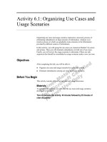
12.1 Location Update
12.1.1 Location Update in the BSS
An MS performs LU on several occasions: every time it changes the location
area, periodically, when a periodic location update is active, or with IMSI
attach/detach switched on at the time when it is subsequently turned on again.
The only subsystems shown in Figure 12.2 are the MSC/VLR, BSC, BTS, and
MS. Nevertheless, if the VLR area changes, the HLR, as well as the old VLR,
are involved, too. Furthermore, if the equipment-check is active, the EIR is also
involved. Figure 12.3 shows LU from the perspective of the NSS.
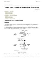
12.1.2 Location Update in the NSS
Figure 12.3 shows a LU in which the VLR changes. In this case, the HLR
is particularly involved in the overall process. When the LU involves no VLR
change, the HLR does not need to be accessed. The HLR only has information
about the VLR area of a subscriber; it has no information about the details of
the location area. If the equipment check is turned on, the EIR is checked with
every activity of an MS.
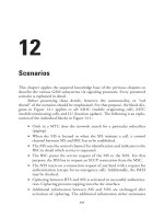
12.2 Equipment Check
The GSM standard enables a network operator to not only verify the identity
of a subscriber by means of authentication but also to check the mobile equip-
ment (ME) as such, which is identified by a unique number, the IMEI. This
targets particularly the theft of mobile equipment.
Scenarios
227
228GSMNetworks:Protocols,Terminology,andImplementation
Air-interface Abis-interface A-interface Explanation
The MS requests a control channel from the BSC.
The BTS decodes the CHAN_REQ, calculates the distance
MS ↔BTS (timing advance), and forwards all this information
to the BSC. Please note that the CHAN_REQ already indicates
which service the MS requests (Location Update, in this case)
After the CHAN_RQD is received and processed, the BSC
informs the BTS which channel type and channel number
shall be reserved (CHAN_ACT).
The BTS confirms with a CHAN_ACT_ACK that it received
and processed the CHAN_ACT.
The BSC sends the IMM_ASS_CMD, which activates the
previously reserved channel. The BTS sends this information
over an AGCH to the MS. The MS finds “its” IMM_ASS_CMD by
means of the request reference, which is already contained in
the CHAN_REQ.
Layer 2, the LAPD connection is activated only now.
m
The MS sends a SABM to the BTS, which (differently from
LAPD) already contains data (LOC_UPD_REQ in this case).
BTS
TRX
BSC
MSC
VLR
CCCH (RACH)/RR
CHAN_REQ [reason, refer.]
CCCH (AGCH)/RR
IMM_ASS_CMD
[TA, channel, refer., FN]
SDCCH/SABM/MM
LOC_UPD_REQ
[TMSI/IMSI, last CI LAC]+
I/CCM/CHAN_RQD
[CHAN_REQ, TA, FN]
I/DCM/CHAN_ACT
[Type, BS/MS-Power, DTX?]
I/DCM/CHAN_ACT_ACK/
[Frame Number]
I/CCM/IMM_ASS_CMD/
[TA, channel, refer., FN]
Figure 12.2 Location update on the BSS interfaces.
Scenarios
229
Air-interface Abis-interface A-interface Explanation
BTS
TRX
BSC
MSC
VLR
The BTS confirms that a LAPD
m
connection was established by
sending an UA message, which repeats the LOC_UPD_REQ.
The BTS passes LOC_UPD_REQ to the BSC. Although this is
a transparent MM message, the BSC still processes the
LOC_UPD_REQ in parts, because the BSC amongst others,
requires the Mobile Station Classmark information. The BSC
packs LOC_UPD_REQ, together with the current LAC, and CI into
a CL3I message (Attention: the LOC_UPD_REQ from the MS
contains the old LAC!) and then sends this within a SCCP CR
message to the MSC. The CR message carries not only the
LOC_UPD_REQ to the MSC, but also requests establishment of
an SCCP connection.
If the MSC is able to provide the requested SCCP connection,
then the CR is answered with a CC. A logical connection from the
MS to the MSC/VLR exists from this point in time on.
The MSC/VLR answers the LOC_UPD_REQ with an AUTH_REQ
This message is conveyed to the BSC via the established
SCCP connection.
BSC and BTS transparently forward the AUTH_REQ to the MS.
Most important content is the random number parameter (RAND).
The MS (more precisely the SIM) calculates the result SRES by
feeding RAND and K
j
into the algorithm A3, then transparently
sends SRES in an AUTH_RSP message to the MSC/VLR.
The VLR compares SRES with the value provided by the HLR.
SDCCH/UA/MM
LOC_UPD_REQ
[TMSI/IMSI, last CI LAC]+
SDCCH/I/MM
AUTH_REQ [CKSN, RAND]
SDCCH/I/MM
AUTH_RSP [SRES]
I/RLM/EST_IND
LOC_UPD_REQ
[TMSI/IMSI, latest CI LAC]+
I/RLM/DATA_REQ
AUTH_REQ [CKSN, RAND]
I/RLM/DATA_IND
AUTH_RSP [SRES]
CR/BSSM/CL3I [new
CI LAC] LOC_UPD_REQ
[TMSI/IMSI, last CI LAC ]
+
+
CC (Connection Confirmed)
[-/-]
DT1/DTAP
AUTH_REQ [CKSN, RAND]
DT1/DTAP
AUTH_RSP [SRES]
Figure 12.2 (continued)
230GSMNetworks:Protocols,Terminology,andImplementation
Air-interface Abis-interface A-interface Explanation
BTS
TRX
BSC
MSC
VLR
The MSC/VLR switches on ciphering, if the result from the
authentication is correct. For this purpose, the MSC/VLR sends
information to both, the MS and the BTS.
The BTS extracts its part form the ENCR_CMD message, which is
K
c
and sends the rest in a CIPH_MOD_CMD message to the MS.
The CIPH_MOD_CMD message only contains the information,
which cipher algorithm (A5/X) shall be used.
The MS confirms, by sending a CIPH_MOD_COM message
that ciphering was activated.
If Equipment Check is active, then the MSC/VLR requests the MS
to provide its IMEI. This is done in an IDENT_REQ message, which
is transparent for the BSS. Please note that the IDENT_REQ
message also allows to request the TMSI or the IMSI. The
equipment check may be performed at almost any time during
the scenario, or in other words, is not tied to this place of the
scenario.
The MS transparently transmits its IMEI in an IDENT_RSP
message to the MSC/VLR, where it is checked by means of the
EIR, whether that equipment is registered stolen or not approved.
The MSC/VLR assigns a TMSI, which is used instead of the IMSI
in order to make tracking of subscribers more difficult.
TMSI_REAL_CMD is also a transparent message between
MSC/VLR and MS. The most important content of this message
is the new TMSI. Please note that the assignment of a TMSI
may also take place at the end within the LOC_UPD_ACC.
SDCCH/I/RR
CIPH_MOD_CMD [A5/X]
SDCCH/I/RR
CIPH_MOD_COM [-/-]
I/DCM/ENCR_CMD
[KC, CIPH_MOD_CMD]
I/RLM/DATA_IND
CIPH_MOD_COM [-/-]
SDCCH/I/MM
IDENT_REQ [IMEI, ...]
SDCCH/I/MM
IDENT_RSP [IMEI, ...]
SDCCH/I/MM
TMSI_REAL_CMD [TMSI]
I/RLM/DATA_REQ
IDENT_REQ [IMEI, ...]
I/RLM/DATA_IND
IDENT_RSP [IMEI, ...]
I/RLM/DATA_REQ
TMSI_REAL_CMD [TMSI]
DT1/BSSM
CIPHER_MODE_CMD
[KC, A5/X]
DT1/BSSM
CIPHER_MODE_CMP [-/-]
DT1/DTAP
IDENT_REQ [IMEI, ...]
DT1/DTAP
IDENT_RSP [IMEI, ...]
DT1/DTAP
TMSI_REAL_CMD [TMSI]
Figure 12.2 (continued)
Scenarios
231
Air-interface Abis-interface A-interface Explanation
BTS
TRX
BSC
MSC
VLR
The MS confirms with a TMSI_REAL_COM that the new TMSI
was received and stored. If the new TMSI is assigned with a
LOC_UPD_ACC, then the TMSI_REAL_COM is obviously sent
only after the LOC_UPD_ACC.
Sending of the transparent LOC_UPD_ACC message
confirms that the MSC/VLR has stored the new Location
Area (LAI). This concludes the Location Update process.
The control channel that was occupied on the Air-interface has to
be released, after the Location Update scenario has ended.
For this purpose, the MSC sends the CLR_CMD message to the
BSC. The BSC passes this command in a CHAN_REL to the BTS,
which passes it to the MS. By sending a DEACT_SACCH, the BSC
requests the BTS to cease sending of SACCH messages
(SYS_INFO 5/6).The MS reacts on receiving a CHAN_REL
message by sending a DISC (LAPD ).
m
This requests from the BTS to release its Layer 2 connection.
The BTS confirms release of the Layer 2 connection by sending an
UA message. Towards the BSC, the BTS confirms release of the
Air-interface connection by sending of a REL_IND message. The
BSC forwards this acknowledgment in a CLR_CMP to the MSC.
The BSC requests the TRX in a RF_CHAN_REL to release the
occupied resources on the Air-interface.
RLSD requests release of the SCCP resources.
RF_CHAN_REL_ACK confirms release on the Air-interface.
RLC confirms release of the SCCP resources.
SDCCH/I/MM
TMSI_REAL_COM [-/-]
SDCCH/I/MM
LOC_UPD_ACC [e.g. TMSI]
SDCCH/I/RR
CHAN_REL [reason]
SDCCH/DISC
(LAPDm)
SDCCH/UA
(LAPDm)
I/RLM/DATA_IND
TMSI_REAL_COM [-/-]
I/RLM/DATA_IND
LOC_UPD_ACC [e.g. TMSI]
I/RLM/DATA_REQ
CHAN_REL [reason]
I/DCM/DEACT_SACCH
[-/-]
I/RLM/REL_IND
[-/-]
I/DCM/RF_CHAN_REL
[-/-]
I/DCM/RF_CH_REL_ACK
[-/-]
DT1/DTAP
TMSI_REAL_COM [-/-]
DT1/DTAP
LOC_UPD_ACC [e.g., TMSI]
DT1/BSSM
CLR_CMD [reason normal]=
DT1/BSSM
CLR_CMP [-/-]
RLSD (Released)
[-/-]
RLC (Release complete)
[-/-]
Figure 12.2 (continued)
232GSMNetworks:Protocols,Terminology,andImplementation
New
Old
A-interface 1st D-interface 2nd D-interface Explanation
on G-Interface
The new VLR requests the authentication data (SRES, RAND, K
i
) from the
old VLR, after receiving a LOC_UPD_REQ.The old VLR can be determined
from the LAC, sent in a LOC_UPD_REQ.
·
·
on G-Interface
·
The old VLR provides the new VLR with the authentication
data, which were originally provided by the HLR.
·
·
After sending LOC_UPD_ACC, the new VLR informs the HLR that the MS
has changed the VLR area. Subsequently, the HLR requests the old VLR in
a cancelLocation message to delete the respective subscriber data.
Simultaneously, the new VLR receives all subscriber data in a
insertSubscriberData message. Both commands are confirmed
by the old and the new VLR, respectively.
The HLR confirms to the new VLR that the subscriber data was updated.
The Location Update procedure may be closed from both the VLR and the
HLR.
MSC
VLR
HLR
MSC
VLR
BSC
CR/BSSM/CL3I
LOC_UPD_REQ
[e.g., TMSI]
DT1/DTAP
LOC_UPD_ACC
[e.g., TMSI]
UDT/BEGIN
sendIdentification [e.g., TMSI]
UDT/END
sendIdentification [Authentication data, IMSI]
UDT/BEGIN
updateLocation
[IMSI,LMSI, new VLR]
UDT/CON
insertSubscriberData
[SS data, MSISDN,
subscriber state]
UDT/CON
insertSubscriberData
[-/-]
UDT/END
updateLocation [-/-]
UDT/END
cancelLocation [IMSI]
UDT/BEGIN
cancelLocation [IMSI]
Figure 12.3 Location update on the NSS interfaces.
For that purpose, the NSS includes a database, the EIR, that contains
information such as the serial numbers of barred mobile equipment. Figure 12.4
illustrates the process of an equipment check between MSC/VLR and EIR.
12.3 Mobile Originating Call
12.3.1 Mobile Originating Call in the BSS
The MS initiates a network access with a MOC. The network access is specified
in more detail in the first message that the MS sends (CM_SERV_REQ) on
the SDCCH. The reasons for such a request could be a regular telephone call,
transfer of MO-SMS, activation of a supplementary service, or an emergency
call. The CM_SERV_ACC message, shown in Figure 12.5 as a confirmation of
a CM_SERV_REQ, is used only when ciphering is not active. If ciphering is
active, the MS, when receiving the CIPH_MOD_CMD message, interprets it
as a positive acknowledgment from the network for the service request.
Figure 12.5 illustrates the MOC on the BSS interfaces. In addition, Figure 12.6
explains which signaling is taking place during an active connection.
12.3.2 Mobile Originating Call in the NSS
From the perspective of the NSS, a connection request of a subscriber can be
directed as follows:
1. To the same PLMN (MS-to-MS call);
2. To another PLMN (MS-to-MS call);
3. To the ISDN (digital);
4. To the PSTN (analog).
In case 1, ISUP signaling is used between both MSCs, after the HLR of the
called subscriber has provided the necessary routing information. ISUP is also
used in cases 2 and 3. There is no principle difference between a call to another
PLMN and to an ISDN.
Figure 12.7 shows signaling for the MOC, which applies to cases 1, 2,
and 3. (Query of the routing information is discussed in Section 12.4.2.)
In case 4 (PSTN), the gateway MSC has to provide the necessary conversion
between digital and analog signaling.
Scenarios
233
234GSMNetworks:Protocols,Terminology,andImplementation
A-interface
New
F-interface Explanation
When Equipment Check is active, the MSC/VLR requests the IMEI (international mobile
equipment identity) from the MS by means of an IDENT_REQ message.
After receiving the IMEI in the IDENT_RSP message, the MSC/VLR sends this IMEI in
a checkIMEI message to the EIR, in order to be checked there.
A positive result is returned to the MSC/VLR, if the IMEI is not included in a “black list“.
If, e.g., the MS is reported stolen, then the OMC is informed.
BSC
MSC
VLR
HLR
DT1/DTAP
IDENT_REQ [IMEI]
DT1/DTAP
IDENT_RSP [IMEI]
UDT/BEGIN
checkIMEI [IMEI]
UDT/END
checkIMEI [IMEI, Status]
Figure 12.4 Scenario of checking the IMEI.
Scenarios
235
Air-interface Abis-interface A-interface Explanation
The MS request assignment of a control channel from the BSC.
The BTS decodes the CHAN_REQ, calculates the distance
MS ↔ BTS (Timing Advance) and returns the complete
information in a CHAN_RQD to the BSC.
Please note that the CHAN_REQ already indicates, which service
an MS requests (in this case: MOC).
After receiving and processing a CHAN_RQD, the BSC informs
the BTS, which channel type and which channel number shall be
reserved (CHAN_ACT).
The BTS acknowledges with a CHAN_ACT_ACK that it received
and processed the CHAN_ACT.
The BSC sends the IMM_ASS_CMD, which activates the
previously reserved channel. The BTS sends this information over
an AGCH to the MS. The MS finds “its” IMM_ASS_CMD by
means of the request reference, which the CHAN_REQ already
contains.
BTS
TRX
BSC
MSC
VLR
CCCH (RACH)/RR
CHAN_REQ [reason, refer.]
CCCH (AGCH)/RR
IMM_ASS_CMD
[TA, channel, refer., FN]
I/CCM/CHAN_RQD
[CHAN_REQ, TA, FN]
I/DCM/CHAN_ACT
[Type, BS/MS-Power, DTX?]
I/DCM/CHAN_ACT_ACK
[Frame Number]
I/CCM/IMM_ASS_CMD
[TA, channel, refer., FN]
Figure 12.5 Mobile originating call in the BSS.
236GSMNetworks:Protocols,Terminology,andImplementation
Air-interface Abis-interface A-interface
Explanation
BTS
TRX
BSC
MSC
VLR
The MS requests from the BTS, by sending a SABM (LAPD ) that
m
a Layer 2 connection be established. It contains a
CM_SERV_REQ, which identifies the subscriber (IMSI or TMSI)
and specifies the requested service. The BTS confirms that a
Layer 2 was established by repeating the CM_SERV_REQ
in an UA message (LAPD ) and simultaneously forwards this
m
information to the BSC. The BSC partly processes the
CM_SERV_REQ (the BSC needs the Mobile Station Classmark)
and LAC, as well as CI are added. The complete information is
packed in a CR (SCCP) as a CL3I (BSSM) and sent to the MSC.
The CR also serves as a request for a SCCP connection.
The MSC answers CR with a CC if it is able to provide the
requested SCCP connection. From this time on, a logical
connection exists from the MS to the MSC/VLR.
The MSC/VLR answers to the CM_SERV_REQ with AUTH_REQ
This message is sent to the BSC over the established SCCP
connection.
BSC and BTS transparently forward the AUTH_REQ to the MS.
Most important content is RAND, the random number.
The MS (more precisely the SIM) calculates the result SRES, by
applying RAND and K
j
to A3. This result is transparently returned
to the MSC/VLR in an AUTH_RSP message.
The VLR compares SRES with the value, which the HLR had
provided. Authentication is successful, if the two match. Then the
MSC/VLR confirms the requested service in a CM_SERV_ACC
message (however, only if ciphering is not active).
SDCCH/SABM/MM
CM_SERV_REQ [MS data]
SDCCH/UA/MM
CM_SERV_REQ [MS data]
SDCCH/I/MM
AUTH_REQ [CKSN, RAND]
SDCCH/I/MM
AUTH_RSP [SRES]
SDCCH/I/MM
CM_SERV_ACC [-/-]
I/RLM/EST_IND
CM_SERV_REQ [MS data]
I/RLM/DATA_REQ
AUTH_REQ [CKSN, RAND]
I/RLM/DATA_IND
AUTH_RSP [SRES]
I/RLM/DATA_REQ
CM_SERV_ACC [-/-]
CR/BSSM/CL3I [CI LAC]
CM_SERV_REQ
+
CC (Connection Confirmed)
[-/-]
DT1/DTAP
AUTH_REQ [CKSN, RAND]
DT1/DTAP
AUTH_RSP [SRES]
DT1/DTAP
CM_SERV_ACC [-/-]
Figure 12.5 (continued)
Scenarios
237
Air-interface Abis-interface A-interface
Explanation
BTS
TRX
BSC
MSC
VLR
If ciphering is active, then no CM_SERV_ACC is sent, but
ciphering is switched on. For this purpose, the MSC/VLR
sends information to both the BTS as well as the MS. The BTS
extracts its part (K
c
) from the ENCR_CMD message and sends
the rest in a CIPH_MOD_CMD message to the MS.
The CIPH_MOD_CMD message only contains the information,
which algorithm A5/X the MS shall use.
The MS confirms by sending a CIPH_MOD_COM message
that ciphering was activated.
The MSC/VLR requests the MS to provides its IMEI, if Equipment
Check is active. This is performed for the BSS transparent,
IDENT_REQ message. Please note that the IDENT_REQ
message, can also be used to request the TMSI or the IMSI.
The Equipment Check can be performed during almost any time
during this scenario and is thus not tied to this position.
The MS transparently transmits its IMEI in an IDENT_RSP
message to the MSC/VLR, where, by utilizing the EIR, it is
checked if the MS is reported stolen or not certified.
The MSC/VLR assigns a TMSI in place of the IMSI, in order to
make tracking of subscribers more difficult. This TMSI is used to
temporarily identify a subscriber. The TMSI_REAL_CMD is also a
transparent message between MS and MSC/VLR. The most
important information of this message is the new TMSI.
The MS confirms with TMSI_REAL_COM that the TMSI was
received and stored.
SDCCH/I/RR
CIPH_MOD_CMD [A5/X]
SDCCH/I/RR
CIPH_MOD_COM [-/-]
SDCCH/I/MM
IDENT_REQ [IMEI, ...]
SDCCH/I/MM
IDENT_RSP [IMEI, ...]
SDCCH/I/MM
TMSI_REAL_CMD [TMSI]
SDCCH/I/MM
TMSI_REAL_COM [-/-]
I/DCM/ENCR_CMD [KC
CIPH_MOD_CMD]
I/RLM/DATA_IND
CIPH_MOD_COM [-/-]
I/RLM/DATA_REQ
IDENT_REQ [IMEI, ...]
I/RLM/DATA_IND
IDENT_RSP [IMEI, ...]
I/RLM/DATA_REQ
TMSI_REAL_CMD [TMSI]
I/RLM/DATA_IND
TMSI_REAL_COM [-/-]
DT1/BSSM
CIPHER_MODE_CMD
[KC, A5/X]
DT1/BSSM
CIPHER_MODE_CMP [-/-]
DT1/DTAP
IDENT_REQ [IMEI, ...]
DT1/DTAP
IDENT_RSP [IMEI, ...]
DT1/DTAP
TMSI_REAL_CMD [TMSI]
DT1/DTAP
TMSI_REAL_COM [-/-]
Figure 12.5 (continued)
238GSMNetworks:Protocols,Terminology,andImplementation
Air-interface Abis-interface A-interface
Explanation
BTS
TRX
BSC
MSC
VLR
The SETUP message, which is transparently sent from the MS to
the MSC/VLR, contains the directory number of the called party.
After the MSC/VLR received this information, it sends (in case of
ISDN) an IAM message (ISUP), in order to set up the connection.
and that the MSC is processing the call set up.
At this time, if OACSU (Off Air Call SetUp) is not active, the
MSC sends ASS_REQ to the BSC. Most important information is,
which (speech) channel shall be used for this connection on the
A-Interface between MSC and BSC.
The physical situation on the Air-interface can be queried, by
sending a PHY_CONTEXT_REQ message, before the BSC
assigns the TCH on the Air-interface. In particular the actual
distance to the MS and the current power settings of the MS are
interesting. These data are conveyed to the BSC in a
PHY_CONTEXT_CONF message.
After receiving and processing of the ASS_REQ, the BSC informs
the BTS, which channel type and what channel number
shall be reserved (CHAN_ACT).
The BTS confirms with CHAN_ACT_ACK that it received and
processed the CHAN_ACT.
With an ASS_CMD, the BSC assigns the traffic channel, which
the MS and the BTS shall use on the Air-interface. The most
important data of ASS_CMD are TRX and TS.
I/RLM/DATA_IND
SETUP [called directory no]
SDCCH/I/CC
SETUP [called directory no]
SDCCH/I/CC
CALL_PROC [-/-]
SDCCH/I/RR
ASS_CMD [Data of the TCH]
I/RLM/DATA_REQ
CALL_PROC [-/-]
I/DCM
PHY_CONTEXT_REQ [-/-]
I/DCM
PHY_CONTEXT_CONF
[act. TA, MS BS power]+
I/DCM/CHAN_ACT
[Type, BS/MS power, DTX ?]
I/DCM/CHAN_ACT_ACK
[Frame Number]
I/RLM/DATA_REQ
ASS_CMD [Data of the TCH]
DT1/DTAP
SETUP [called directory no.]
DT1/DTAP
CALL_PROC [-/-]
DT1/BSSM
ASS_REQ [channel on A-i/f.]
The network confirms with CALL_PROC that the IAM was sent,
Figure 12.5 (continued)
Scenarios
239
Air-interface Abis-interface A-interface
Explanation
BTS
TRX
BSC
MSC
VLR
The BTS expects that a SABM is sent from the MS, using the
I/RLM/EST_IND [-/-]
new channel, which enables the LAPD
m
Layer 2 connection. The
FACCH/UA
BTS confirms with a UA message (LAPD ) that a SABM was
m
received and Layer 2 was established. At the same time, this
confirmation is sent in a EST_IND message over the Abis-
I/RLM/DATA_IND
ASS_COM
interface to the BSC. With sending of ASS_COM, the traffic
DT1/BSSM
ASS_COM
channel on Layer 3 is operational. This also acknowledges the
ASS_REQ to the MSC.
I/DCM/RF_CHAN_REL
[-/-]
The BSC releases the previously occupied control channel, which
was used for the call set up, by sending of RF_CHAN_REL.
The BTS confirms release with RF_CH_REL_ACK.
I/DCM/RF_CH_REL_ACK
[-/-]
DT1/DTAP
ALERT/PROGRESS
When the MSC receives ACM (ISUP) for the connection set up,
I/RLM/DATA_REQ
ALERT/PROGRESS
it either sends an ALERT or a PROGRESS message to the MS.
ALERT is used to indicate a change of state within the MS, e.g.,
generation of a ring tone. PROGRESS is used when no change of
state is involved, e.g., when the ring tone is sent “inband” from
the NSS. For more differences between, ALERT and PROGRESS,
please refer to Chapter 7, “The Air-interface”.
DT1/DTAP
CON
I/RLM/DATA_REQ
CON
When the MSC/VLR receives the ANS message (ISUP) from the
FACCH/I/CC
CON
called side, then the call is through connected, i.e., the called
party CON message is transparentlyhas accepted the call. The
sent to CONthe MS. The actual call begins with receiving the
FACCH/I/CC
CON_ACK
message. CON_ACK message to the MSC/VLRThe MS sends a
in order to acknowledge this message and start of charging.
DT1/DTAP
CON_ACK
FACCH/SABM
FACCH/I/RR
ASS_COM
FACCH/I/CC
ALERT/PROGRESS
I/RLM/DATA_IND
CON_ACK
Figure 12.5 (continued)
240GSMNetworks:Protocols,Terminology,andImplementation
Air-interface Abis-interface A-interface
Explanation
BTS
TRX
BSC
MSC
VLR
I/RLM/DATA_IND
DISC [reason]
One party, here the MS side, presses the “End” button when the
DT1/DTAP
DISC [reason]
connection between the two parties shall be released. This
results in a DISC message, which is transparently sent form the
MS to the MSC/VLR. The MSC answers DISC with REL message,
DT1/DTAP
REL [reason]
which is also transparently sent to the MS.
FACCH/I/CC
REL [reason]
I/RLM/DATA_REQ
REL_COM [reason]
DT1/DTAP
REL_COM [reason]
From the perspective of call control, the connection is considered
released when the MSC/VLR has received a REL_COM message.
DT1/BSSM
CLR_CMD [reason normal]=
After the call has ended from the call control perspective, the
occupied traffic channel on the Air-interface has to be released.
For this purpose, the MSC sends the CLR_CMD message to the
BSC. The BSC forwards the CHAN_REL to the BTS and the MS.
I/DCM/DEACT_SACCH
[-/-]
By sending DEACT_SACCH, the BSC requests the BTS to cease
sending of SACCH messages (SYS_INFO 5 / 6). When the MS
receives a CHAN_REL message, it reacts with a DISC (LAPD ).
m
This requests the BTS to release the Layer 2 connection.
The BTS confirms release of the Layer 2 connection by sending a
I/RLM/REL_IND
[-/-]
UA message. Towards the BSC, the BTS confirms release of
DT1/BSSM
CLR_CMP [-/-]
the Air-interface connection by sending a REL_IND message.
The BSC passes this acknowledgment in a CLR_CMP to the MSC.
With the RF_CHAN_REL, the BSC requests the TRX to release
I/DCM/RF_CHAN_REL
[-/-]
the occupied resources on the Air-interface.
RLSD (Released)
[-/-]
RLSD requests release of the SCCP resources.
I/DCM/RF_CH_REL_ACK
[-/-]
RF_CHAN_REL_ACK acknowledges release on the Air-interface.
RLC (Release Complete)
[-/-]
RLC acknowledges that the SCCP resources have been released.
FACCH/I/CC
DISC [reason]
FACCH/I/CC
REL_COM [reason]
FACCH/I/RR
CHAN_REL [reason]
FACCH/DISC
(LAPD )
m
FACCH/UA
(LAPD )
m
I/RLM/DATA_REQ
REL [reason]
I/RLM/DATA_REQ
CHAN_REL [reason]
Figure 12.5 (continued)
Scenarios
241
Air-interface Abis-interface A-interface
Explanation
BTS
TRX
BSC
MSC
VLR
Active phase of a call
UI/DCM/MEAS_RES
[ UL message [MEAS_REP]]
Both MS and BTS send their measurement results
already during call set up, once per multiframe, in a
MEAS_RES/MEAS_REP message to the BSC. The SACCH
(uplink) takes care of the transport on the Air-interface.
In the downlink direction, the SACCH sends the SYS_INFOS 5
and 6 (for GSM) once per multiframe to the MS.
Furthermore, the Layer 1 part of the SACCH contains the
parameter, which the MS has to set, i.e., transmission power
and timing advance (TA), which reflects the distance. Changes
of the MS transmission power are controlled by the BSC with a
MS_POWER_CON message. The same applies for the
transmission power of the BTS, which are controlled by the BSC
with a BS_POWER_CON message.
SACCH
[e.g., SYS_INFO 5 or 6]
I/DCM
MS_POWER_CON
·
·
I/DCM
BS_POWER_CON
·
SACCH/UI/RR
MEAS_REP [DL message]
UI/DCM/MEAS_RES
[ UL message [MEAS_REP]]
SACCH
[e.g., SYS_INFO 5 or 6]
SACCH/UI/RR
MEAS_REP [DL message]
480 ms
Figure 12.6 Signaling traffic during a connection.
242GSMNetworks:Protocols,Terminology,andImplementation
A-interface E-interface ISDN Explanation
CR/BSSM/CL3I
CM_SERV_REQ [MS data]
Receiving of the initial CM_SERV_REQ message involves only
MSC/VLR and BSS (of course the MS as well). Routing of a
MOC is not possible without the number of the called party.
DT1/DTAP
SETUP [called directory no.]
The SETUP message provides the network with the number
which the MS has dialed. An IAM is sent to the gateway MSC,
in case of ISDN (or other PLMN). The gateway MSC, in turn,
forwards the IAM to the ISDN exchange.
ISUP/IAM
Initial Address Message
DT1/DTAP
CALL_PROC [-/-]
When the call routing in the ISDN is complete (it rings), then
the ISDN exchange sends an ACM back to the gateway MSC,
which forwards the ACM to the active MSC. The receipt of the
ACM is indicated to the MS as ALERT or PROGRESS message.
ISUP/ACM
Address Complete Message
DT1/DTAP
ALERT/PROGRESS
G-MSC
MSC
VLR
BSC
ISDN
VST
ISUP/IAM
Initial Address Message
ISUP/ACM
Address Complete Message
Figure 12.7 Mobile originating call in the NSS.
Scenarios
243
A-interface E-interface ISDN Explanation
ISUP/ANM
ANswer Message
The very moment the called party takes the call, the ISDN
exchange sends an ANM back to the active MSC. Then the
MS receives a CON message and the two parties are finally
connected (Note: Without CON_ACK).
ISUP/ANM
ANswer Message
DT1/DTAP
CON
DT1/DTAP
CON_ACK
Active phase of the call
DT1/DTAP
DISC [reason]
The MSC receives a DISC when the MS subscriber ends the
call. It reacts with a REL message (ISUP) toward the ISDN
and a REL message (BSSAP) toward the MS. The ISDN
exchange confirms with RLC (ISUP). The MS confirms the
release with REL_COM. In particular the termination of a call
illustrates the close relationship between ISDN / ISUP on one
hand and call control (CC) on the other.
ISUP/REL
RELease [reason]
ISUP/REL
RELease [reason]
DT1/DTAP
REL [reason]
ISUP/RLC
ReLease Complete [-/-]
DT1/DTAP
REL_COM [reason]
ISUP/RLC
ReLease Complete [-/-]
G-MSC
MSC
VLR
BSC
ISDN
VST
Figure 12.7 (continued)