Máy đào HuynDai R170W-9 (Phần 1) - P3
Bạn đang xem bản rút gọn của tài liệu. Xem và tải ngay bản đầy đủ của tài liệu tại đây (1.07 MB, 15 trang )
3-143-14
GROUP 4 SINGLE OPERATIONGROUP 4 SINGLE OPERATION
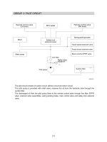
When the right control lever is pulled back, the boom spools in the main control valve are moved to
the up position by the pilot oil pressure from the remote control valve.
The oil from the A1 and A2 pump flows into the main control valve and then goes to the large
chamber of boom cylinders. At the same time, the oil from the small chamber of boom cylinders
returns to the hydraulic oil tank through the boom spool in the main control valve. When this
happens, the boom goes up. The excessive pressure in the boom cylinder head side is prevented
by relief valve. When the boom is up and the control lever is returned to neutral position, the circuit
for the holding pressure at the head side of the boom cylinder is closed by the boom holding valve.
This prevents the hydraulic drift of boom cylinder.
1. BOOM UP OPERATION1. BOOM UP OPERATION
B1
A1
A2
B2
P
T2
T4(TGP)
ACC1GP
BR1
BR2
ACC2
ACC1
CT4
P
PGP
CT3
CT1
CT2
dr3
dr2
BRAKE VALVE
ARM
CYLINDER
BUCKET
CYLINDER
TRAVEL MOTOR
FRONT AXLE
REAR AXLE
OSCILLATING
CYLINDER
TRANSMISSION
SWING MOTOR
TURNING
JOINT
BOOM CYLINDER
TP
M2
P
T
P
T
M
K
B
AC1
T3
P1
P1P2
L R
M1
Pu
Pc42
Pb3
Pd41
DR1
Pb21
Pb20
Pa20
Pb1
Pa1
T1
Pc3
Pa21
V3
Pd2
D2
C2
Pc1
D1
C1
Pd1
Ai
B4
B5
A5
Pa5
Pb5
Pa4
Pb4
C5
D5
D4
C4
Pc40
Pd40
DR3
Pc5
Pd5
Rs
C6
D6
P03
PS
P1P2
P3
P0
Patt
P02
PS
Pn1
Pi1(Pump)
Pi2(Pump)
Pn2
PS
PS
Pd6
Pc6
PS
Pc2
P05
Puo
Pc41
DR5
DR2
DR4
DR0
SH
(S/Motor)
ARM 1
BOOM 2
SWING
TRAVEL
OPT-C
BOOM 1
ARM
REGEN
BUCKET
OPT-B
DOZER
ARM 2
PILOT
PUMP
HYDRAULIC TANK
BOOM
HOLDING
VALVE
RELIEF
VALVE
DOZER/ OUTRIGGER CYLINDER
A1
PUMP
A2
PUMP
P04
17W93HC10
3-153-15
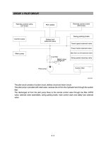
When the right control lever is pushed forward, the boom 1 spool in the main control valve is moved
to the down position by the pilot oil pressure from the remote control valve.
The oil from the A2 pump flows into the main control valve and then goes to the small chamber of
boom cylinders. At the same time, the oil from the large chamber of boom cylinders returns to the
hydraulic tank through the boom 1 spool in the main control valve.
When the down speed of boom is faster, the oil returned from the large chamber of boom cylinder
combines with the oil from the A2 pump, and flows into the small chamber of the cylinder.
This prevents cylinder cavitation by the negative pressure when the A2 pump flow can not match the
boom down speed. And the excessive pressure in the boom cylinder rod side is prevented by the
relief valve.
2. BOOM DOWN OPERATION2. BOOM DOWN OPERATION
B1
A1
A2
B2
P
T2
T4(TGP)
ACC1GP
BR1
BR2
ACC2
ACC1
CT4
P
PGP
CT3
CT1
CT2
dr3
dr2
BRAKE VALVE
ARM
CYLINDER
BUCKET
CYLINDER
TRAVEL MOTOR
FRONT AXLE
REAR AXLE
OSCILLATING
CYLINDER
TRANSMISSION
SWING MOTOR
TURNING
JOINT
BOOM CYLINDER
TP
M2
P
T
P
T
M
K
B
AC1
T3
P1
P1P2
L R
M1
Pu
Pc42
Pb3
Pd41
DR1
Pb21
Pb20
Pa20
Pb1
Pa1
T1
Pc3
Pa21
V3
Pd2
D2
C2
Pc1
D1
C1
Pd1
Ai
B4
B5
A5
Pa5
Pb5
Pa4
Pb4
C5
D5
D4
C4
Pc40
Pd40
DR3
Pc5
Pd5
Rs
C6
D6
P03
PS
P1P2
P3
P0
Patt
P02
PS
Pn1
Pi1(Pump)
Pi2(Pump)
Pn2
PS
PS
Pd6
Pc6
PS
Pc2
P05
Puo
Pc41
DR5
DR2
DR4
DR0
SH
(S/Motor)
ARM 1
BOOM 2
SWING
TRAVEL
OPT-C
BOOM 1
ARM
REGEN
BUCKET
OPT-B
DOZER
ARM 2
PILOT
PUMP
HYDRAULIC TANK
DOZER/ OUTRIGGER CYLINDER
A1
PUMP
A2
PUMP
P04
RELIEF
VALVE
17W93HC11
3-163-16
When the left control lever is pulled back, the arm spools in the main control valve are moved to the
arm in position by the pilot oil pressure from the remote control valve.
The oil from the A1 and A2 pump flows into the main control valve and then goes to the large
chamber of arm cylinder.
At the same time, the oil from small chamber of arm cylinder returns to the hydraulic oil tank through
the arm spool in the main control valve. When this happens, the arm rolls in.
The excessive pressure in the arm cylinder head side is prevented by relief valve.
The cavitation which will happen to the head side of the arm cylinder is also prevented by the make-
up valve in the main control valve.
3. ARM IN OPERATION3. ARM IN OPERATION
B1
A1
A2
B2
P
T2
T4(TGP)
ACC1GP
BR1
BR2
ACC2
ACC1
CT4
P
PGP
CT3
CT1
CT2
dr3
dr2
BRAKE VALVE
ARM
CYLINDER
BUCKET
CYLINDER
TRAVEL MOTOR
FRONT AXLE
REAR AXLE
OSCILLATING
CYLINDER
TRANSMISSION
SWING MOTOR
TURNING
JOINT
BOOM CYLINDER
TP
M2
P
T
P
T
M
K
B
AC1
T3
P1
P1P2
L R
M1
Pu
Pc42
Pb3
Pd41
DR1
Pb21
Pb20
Pa20
Pb1
Pa1
T1
Pc3
Pa21
V3
Pd2
D2
C2
Pc1
D1
C1
Pd1
Ai
B4
B5
A5
Pa5
Pb5
Pa4
Pb4
C5
D5
D4
C4
Pc40
Pd40
DR3
Pc5
Pd5
Rs
C6
D6
P03
PS
P1P2
P3
P0
Patt
P02
PS
Pn1
Pi1(Pump)
Pi2(Pump)
Pn2
PS
PS
Pd6
Pc6
PS
Pc2
P05
Puo
Pc41
DR5
DR2
DR4
DR0
SH
(S/Motor)
ARM 1
BOOM 2
SWING
TRAVEL
OPT-C
BOOM 1
ARM
REGEN
BUCKET
OPT-B
DOZER
ARM 2
PILOT
PUMP
HYDRAULIC TANK
DOZER/ OUTRIGGER CYLINDER
A1
PUMP
A2
PUMP
P04
MAKE UP
VALVE
RELIEF VALVE
17W93HC12
3-173-17
When the left control lever is pushed forward, the arm spools in the main control valve are moved to
the arm out position by the pilot oil pressure from the remote control valve.
The oil from the A1 and A2 pump flows into the main control valve and then goes to the small
chamber of arm cylinder. At the same time, the oil from the large chamber of arm cylinder returns to
the hydraulic oil tank through the arm spool in the main control valve. When this happens, the arm
rolls out. The cavitation which will happen to the rod side of the arm cylinder is also prevented by the
make-up valve in the main control valve. When the arm is roll out and the control lever is returned to
neutral position, the circuit for the holding pressure at the rod side of the arm cylinder is closed by
the arm holding valve. This prevent the hydraulic drift of arm cylinder.
4. ARM OUT OPERATION4. ARM OUT OPERATION
B1
A1
A2
B2
P
T2
T4(TGP)
ACC1GP
BR1
BR2
ACC2
ACC1
CT4
P
PGP
CT3
CT1
CT2
dr3
dr2
BRAKE VALVE
ARM
CYLINDER
BUCKET
CYLINDER
TRAVEL MOTOR
FRONT AXLE
REAR AXLE
OSCILLATING
CYLINDER
TRANSMISSION
SWING MOTOR
TURNING
JOINT
BOOM CYLINDER
TP
M2
P
T
P
T
M
K
B
AC1
T3
P1
P1P2
L R
M1
Pu
Pc42
Pb3
Pd41
DR1
Pb21
Pb20
Pa20
Pb1
Pa1
T1
Pc3
Pa21
V3
Pd2
D2
C2
Pc1
D1
C1
Pd1
Ai
B4
B5
A5
Pa5
Pb5
Pa4
Pb4
C5
D5
D4
C4
Pc40
Pd40
DR3
Pc5
Pd5
Rs
C6
D6
P03
PS
P1P2
P3
P0
Patt
P02
PS
Pn1
Pi1(Pump)
Pi2(Pump)
Pn2
PS
PS
Pd6
Pc6
PS
Pc2
P05
Puo
Pc41
DR5
DR2
DR4
DR0
SH
(S/Motor)
ARM 1
BOOM 2
SWING
TRAVEL
OPT-C
BOOM 1
ARM
REGEN
BUCKET
OPT-B
DOZER
ARM 2
PILOT
PUMP
HYDRAULIC TANK
ARM
HOLDING
VALVE
RELIEF
VALVE
DOZER/ OUTRIGGER CYLINDER
A1
PUMP
A2
PUMP
P04
MAKE UP VALVE
17W93HC13
3-183-18
When the right control lever is pulled left, the bucket spool in the main control valve is moved to the
roll in position by the pilot oil pressure from the remote control valve.
The oil from the A2 pump flows into the main control valve and then goes to the large chamber of
bucket cylinder.
At the same time, the oil from the small chamber of bucket cylinder returns to the hydraulic oil tank
through the bucket spool in the main control valve. When this happens, the bucket rolls in.
The excessive pressure in the bucket cylinder head side is prevented by relief valve.
The cavitation which will happen to the head side of the bucket cylinder is also prevented by the
make-up valve in the main control valve.
5. BUCKET IN OPERATION5. BUCKET IN OPERATION
B1
A1
A2
B2
P
T2
T4(TGP)
ACC1GP
BR1
BR2
ACC2
ACC1
CT4
P
PGP
CT3
CT1
CT2
dr3
dr2
BRAKE VALVE
ARM
CYLINDER
BUCKET
CYLINDER
TRAVEL MOTOR
FRONT AXLE
REAR AXLE
OSCILLATING
CYLINDER
TRANSMISSION
SWING MOTOR
TURNING
JOINT
BOOM CYLINDER
TP
M2
P
T
P
T
M
K
B
AC1
T3
P1
P1P2
L R
M1
Pu
Pc42
Pb3
Pd41
DR1
Pb21
Pb20
Pa20
Pb1
Pa1
T1
Pc3
Pa21
V3
Pd2
D2
C2
Pc1
D1
C1
Pd1
Ai
B4
B5
A5
Pa5
Pb5
Pa4
Pb4
C5
D5
D4
C4
Pc40
Pd40
DR3
Pc5
Pd5
Rs
C6
D6
P03
PS
P1P2
P3
P0
Patt
P02
PS
Pn1
Pi1(Pump)
Pi2(Pump)
Pn2
PS
PS
Pd6
Pc6
PS
Pc2
P05
Puo
Pc41
DR5
DR2
DR4
DR0
SH
(S/Motor)
ARM 1
BOOM 2
SWING
TRAVEL
OPT-C
BOOM 1
ARM
REGEN
BUCKET
OPT-B
DOZER
ARM 2
HYDRAULIC TANK
MAKE UP
VALVE
RELIEF
VALVE
DOZER/ OUTRIGGER CYLINDER
PILOT
PUMP
A1
PUMP
A2
PUMP
P04
17W93HC14
3-193-19
When the right control lever is pushed right, the bucket spool in the main control valve is moved to
the bucket out position by the pilot oil pressure from the remote control valve.
The oil from the A2 pump flows into the main control valve and then goes to the small chamber of
bucket cylinder.
At the same time, the oil from the large chamber of bucket cylinder returns to the hydraulic oil tank
through the bucket spool in the main control valve. When this happens, the bucket rolls out.
The cavitation which will happen to the rod side of the bucket cylinder is also prevented by the
make-up valve in the main control valve.
6. BUCKET OUT OPERATION6. BUCKET OUT OPERATION
B1
A1
A2
B2
P
T2
T4(TGP)
ACC1GP
BR1
BR2
ACC2
ACC1
CT4
P
PGP
CT3
CT1
CT2
dr3
dr2
BRAKE VALVE
ARM
CYLINDER
BUCKET
CYLINDER
TRAVEL MOTOR
FRONT AXLE
REAR AXLE
OSCILLATING
CYLINDER
TRANSMISSION
SWING MOTOR
TURNING
JOINT
BOOM CYLINDER
TP
M2
P
T
P
T
M
K
B
AC1
T3
P1
P1P2
L R
M1
Pu
Pc42
Pb3
Pd41
DR1
Pb21
Pb20
Pa20
Pb1
Pa1
T1
Pc3
Pa21
V3
Pd2
D2
C2
Pc1
D1
C1
Pd1
Ai
B4
B5
A5
Pa5
Pb5
Pa4
Pb4
C5
D5
D4
C4
Pc40
Pd40
DR3
Pc5
Pd5
Rs
C6
D6
P03
PS
P1P2
P3
P0
Patt
P02
PS
Pn1
Pi1(Pump)
Pi2(Pump)
Pn2
PS
PS
Pd6
Pc6
PS
Pc2
P05
Puo
Pc41
DR5
DR2
DR4
DR0
SH
(S/Motor)
ARM 1
BOOM 2
SWING
TRAVEL
OPT-C
BOOM 1
ARM
REGEN
BUCKET
OPT-B
DOZER
ARM 2
HYDRAULIC TANK
MAKE UP
VALVE
RELIEF
VALVE
DOZER/ OUTRIGGER CYLINDER
PILOT
PUMP
A1
PUMP
A2
PUMP
P04
17W93HC15