Tài liệu xe HONDA ACCORD - P2
Bạn đang xem bản rút gọn của tài liệu. Xem và tải ngay bản đầy đủ của tài liệu tại đây (2.71 MB, 71 trang )
TA08E000000000J1702ABAT00
SUPPLEMENTAL RESTRAINT SYSTEM (SRS) (If steering maintenance is required)
The Accord SRS includes a driver’s airbag in the steering wheel hub, a passenger’s airbag in the dashboard above the
glove box, seat belt tensioners in the front seat belt retractors, seat belt outer lap tensioners in the front seat belt lower
anchor, side curtain airbags in the sides of the roof, and side airbags in the front seat-backs. Information necessary to
safely service the SRS is included in this Shop Manual. Items marked with an asterisk ( ) on the contents page
include or are located near SRS components. Servicing, disassembling, or replacing these items requires special
precautions and tools, and should be done by an authorized Honda dealer.
• To avoid rendering the SRS inoperative, which could lead to personal injury or death in the event of a severe frontal
or side collision, all SRS service work should be done by an authorized Honda dealer.
• Improper service procedures, including incorrect removal and installation of the SRS, could lead to personal injury
caused by unintentional deployment of the airbags, side airbags, and/or side curtain airbags.
• Do not bump or impact the SRS unit, front impact sensors, or side impact sensors, or rear safing sensor when the
ignition switch is ON (II), or for at least 3 minutes after the ignition switch is turned to LOCK (0); otherwise, the
system may fail in a collision, or the airbags may deploy.
• SRS electrical connectors are identified by yellow color coding. Related components are located in the steering
column, front console, dashboard, dashboard lower panel, in the dashboard above the glove box, in the front seats,
in the roof side, and around the floor. Do not use electrical test equipment on these circuits.
07/09/20 19:51:29 62TA000B_170_0001
TA08E000000000J1702ZCAT00
Steering
Power Steering
................................................................
........................................
..............................
........................................
......................
.....................................................
................
....................................................
............................................
.......................................................
................................
.....................................................
............................................................
............................................
...............
........................................
..............
.......................................
........................................
..............................................
........................................
........................................
....................................
.........................
.....................
Special Tools . 17-2
Component Location Index . 17-3
Symptom Troubleshooting Index . 17-4
Symptom Troubleshooting . 17-7
Steering Wheel Rotational Play Check . 17-9
Power Assist Check . 17-9
Steering Linkage and Gearbox Inspection . 17-10
Pump Pressure Test . 17-11
Fluid Leakage Inspection . 17-12
Fluid Replacement . 17-14
Power Steering Hose, Line, and
Pressure Switch Replacement . 17-15
Pump Replacement . 17-17
Pump Overhaul . 17-19
Steering Wheel Removal . 17-26
Steering Wheel Disassembly/Reassembly . 17-27
Steering Wheel Installation . 17-29
Steering Column Removal and Installation . 17-30
Steering Column Inspection . 17-34
Steering Lock Replacement . 17-36
Rack Guide Adjustment . 17-37
Steering Gearbox Removal . 17-38
Steering Gearbox Overhaul . 17-46
Steering Gearbox Installation . 17-61
Tie-rod Ball Joint Boot Replacement . 17-69
Gearbox Mount Cushion Replacement . 17-70
07/09/20 19:51:29 62TA000B_170_0002
01
01
01
01
01
01
01
01
01
01
01
01
01
01
01
01
01
01
01
TA08E000000000J1702PAAT00
Ref. No. Tool Number Description Qty
17-2
Power Steering
Special Tools
07HAG-SF10200 Sizing Tool, 42mm 1
07JAD-PL90100 Oil Seal Driver, 65 mm 1
07MAA-SL00100 Locknut Eye Wrench, 40 mm 1
07MAC-SL00201 Ball Joint Remover, 28 mm 1
07MAK-PY30100 Subhanger Stay 1
07NAG-SR30900 Sizing Tool 22.25 mm 1
07YAG-S2X0100 Sleeve Seal Guide 1
07ZAG-S5A0100 Sizing Tool, 36 mm 1
07RAK-S040111 Pump Joint Adapter 1
07RAK-S040122 Hose Joint Adapter 1
07TAF-SZ50100 End-Packing Remover, 26 x 33 mm 1
07XAG-S0K0200 Piston Seal Ring Guide 1
070AG-SJAA10S Frame Positioning Guide Pin 1
07406-0010001 P/S Pressure Gauge 1
07746-0010100 Bearing Driver Attachment, 32 x 35 mm 1
07746-0030300 Inner Bearing Driver Attachment, 30 mm 1
07946-1870100 Bearing Driver Attachment, 28 x 30 mm 1
07749-0010000 Driver Handle 15 x 135L 1
07965-SA50500 Inner Bearing Driver Attachment, 36 mm 1
07/09/20 19:51:33 62TA000B_170_0003
*01
TA08E20F24500000000DAAT01
17-3
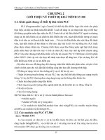
Component Location Index
POWER STEERING FLUID RESERVOIR
POWER STEERING PUMP
DRIVER’S AIRBAG
STEERING WHEEL
STEERING COLUMN
POWER STEERING GEARBOX
Fluid Leakage Inspection:
LHD Model, page 17-12
RHD Model, page 17-13
Fluid Replacement, page 17-14
Power Steering Hose, Line, and
Pressure Switch Replacement:
LHD Model, page 17-15
RHD Model, page 17-16
Drive Belt Inspection:
R20A3 Engine Model, page 4-32
K24Z2, K24Z3 Engine Models, page 4-84
Drive Belt Replacement:
R20A3 Engine Model, page 4-32
K24Z2, K24Z3 Engine Models, page 4-84
Pump Pressure Test, page 17-11
Pump Replacement:
R20A3 Engine Model, page 17-17
Except R20A3 Engine Model, page 17-18
Pump Overhaul, page 17-19
Replacement, page 24-233
Removal, page 17-26
Disassembly/Reassembly:
4-door, page 17-27
2-door, page 17-28
Installation, page 17-29
Removal and Installation,
page 17-30
Inspection, page 17-34
Steering Lock Replacement,
page 17-36
Rack Guide Adjustment, page 17-37
Removal, page 17-38
Overhaul, page 17-46
Installation, page 17-61
Tie-rod Ball Joint Boot Replacement, page 17-69
Gearbox Mount Cushion Replacement, page 17-70
The illustration shows LHD model, RHD model is similar.
07/09/20 19:51:40 62TA000B_170_0004
TA08E20F24500000000HBAT00
Symptom Procedure(s) Also check for
17-4
Power Steering
Symptom Troubleshooting Index
Find the symptom in the chart, and do the related procedures in the order listed until you find the cause.
•
•
•
Hard steering Troubleshoot the system (see page 17-7). Modified
suspension
Damaged
suspension
Incorrect tyre
sizes, tyre
varieties, and
air pressure
Assist (excessively
light steering at high
speed)
Check the rack guide adjustment (see page 17-37). Front wheel
alignment
(see page 18-5)
Shock or vibration
when the steering
wheel is turned to full
lock
1.
2.
3.
4.
Check the drive belt for slippage: R20A3 engine model (see page
4-32), K24Z2, K24Z3 engine models (see page 4-84).
Check the power steering pump fluid pressure (see page 17-11).
Check the rack guide adjustment (see page 17-37).
Overhaul the steering gearbox (see page 17-46).
Steering wheel will not
return smoothly
1.
2.
3.
4.
Check cylinder lines for deformation.
Check the ball joints for binding.
Check wheel alignment (see page 18-5).
Overhaul the steering gearbox (see page 17-46).
Uneven or rough
steering
1.
2.
3.
4.
5.
6.
Check the rack guide adjustment (see page 17-37).
Check the drive belt: R20A3 engine model (see page 4-32),
K24Z2, K24Z3 engine models (see page 4-84).
Check for low or erratic engine idle speed: R20A3 engine model
(see page 11-258), K24Z2, K24Z3 engine models (see page
11-694).
Check for air in the power steering system due to air entering
inlet side of pump.
Check for low fluid level in the power steering reservoir due to
possible leaks in system (see page 17-14).
Overhaul the steering gearbox (see page 17-46).
Steering wheel kicks
back during wide turns
1.
2.
3.
Check for low fluid level in the power steering reservoir due to
possible leaks in the system: LHD model (see page 17-15), RHD
models (see page 17-16).
Check the drive belt: R20A3 engine model (see page 4-32),
K24Z2, K24Z3 engine models (see page 4-84).
Check the power steering pump fluid pressure (see page 17-11).
07/09/20 19:51:40 62TA000B_170_0005
−
−
Symptom Procedure(s) Also check for
17-5
•
•
•
•
•
•
•
•
•
•
•
•
•
•
•
Humming noise from
the power steering
system
1.
2.
3.
4.
5.
Check when the noise occurs:
If the noise is heard during the first 2 3 minutes after starting
the engine in cold weather, this is normal.
If the noise is heard when the wheel is turned with the vehicle
stopped, this is normal due to the fluid pulsation.
Check for air bubbles in the power steering fluid, leak on inlet
side of pump.
Check for particle contamination of fluid and a restricted filter in
the reservoir.
Check for the high-pressure hose touching the subframe or body.
Check for automatic transmission torque converter noise.
Pump pressure
Power steering rack
rattle or chattering
1.
2.
3.
4.
Check for loose steering components (tie-rod and ball joints).
Tighten or replace as necessary.
Check the steering column shaft for wobbling. If the steering
column wobbles, replace the steering column assembly
(see page 17-30).
Check the power steering pump pulley on the shaft comp. for
damage and deterioration, replace the shaft comp. if necessary
(see page 17-20).
Check the rack guide adjustment (see page 17-37).
Hissing from the power
steering system/
foaming fluid
Check the fluid level. If low, fill the reservoir to the proper level
and check for leaks (see page 17-14).
Check the reservoir for leaks.
Check for crushed inlet hose or loose hose clamp allowing air into
the suction side of the system: LHD model (see page 17-15), RHD
model (see page 17-16).
Check the power steering pump shaft oil seal for leaks.
Air in the P/S
fluid
Noise from the power
steering pump
Compare the pump noise at normal operating temperature to
another like vehicle (pump noise during the first 2 3 minutes
after starting the engine in cold weather is normal).
Remove and inspect the pump for wear and damage: R20A3
engine model (see page 17-17), except R20A3 engine model
(see page 17-18).
P/S pump
pressure
Air in the P/S
fluid
Squeaking from the
power steering pump
Check the drive belt: R20A3 engine model (see page 4-32), K24Z2,
K24Z3 engine models (see page 4-84).
Fluid leaks from the
steering gearbox
Fluid leaks from the top of the valve body unit. Overhaul the valve
body unit (see step 23 on page 17-51).
Fluid leaks from the driver’s side boot. Replace the valve oil seal
on the pinion shaft. Replace the cylinder end seal on the gearbox
side.
Fluid leaks from the passenger’s side boot. Replace the cylinder
end seal on the cylinder side.
Fluid leaks from pinion shaft near the lower steering joint bolt.
Overhaul the valve body unit (see step 23 on page 17-51).
Fluid leaks from the steering damping valve covers on the valve
body unit. Replace the valve housing.
(cont’d)
07/09/20 19:51:40 62TA000B_170_0006
Symptom Procedure(s) Also check for
17-6
Power Steering
Symptom Troubleshooting Index (cont’d)
•
•
•
•
•
•
•
•
•
Fluid leaks from the
power steering line
Fluid leaks from the cylinder line connections (flare nuts). Tighten
the connection and retest: LHD model (see page 17-15), RHD
model (see page 17-16).
Fluid leaks from a damaged cylinder line(s). Replace the cylinder
line: LHD model (see page 17-15), RHD model (see page 17-16).
Fluid leaks from the pump outlet hose or return line fitting on the
valve body unit (flare nuts). Tighten the fitting and retest. If it still
leaks, replace the hose, the line, or valve body unit as necessary.
Fluid leaks from the
power steering pump
Fluid leaks from the front oil seal. Replace the front oil seal.
Fluid leaks from the power steering pump housing. Replace the
leaking O-rings or seals (see page 17-19), and if necessary replace
the power steering pump: R20A3 engine model (see page 17-17),
K24Z2, K24Z3 engine models (see page 17-18).
Fluid leaks from the
power steering
reservoir
Fluid leaks from around the reservoir cap because fluid level is too
high. Drain the reservoir to the proper level. If the fluid is aerated
check for an air leak on the inlet side of pump.
Fluid leaks from reservoir. Check the reservoir for cracks and
replace as necessary.
Fluid leaks from the
power steering pump
outlet hose
(high-pressure)
Check the fitting for loose bolts. If the bolts are tight, replace the
fitting O-ring.
Fluid leaks at the swagged joint. Replace the pump outlet hose.
Fluid leaks from the
power steering pump
inlet hose
(low-pressure)
Check the hose for damage, deterioration, or improper assembly.
Replace or repair as necessary.
07/09/20 19:51:40 62TA000B_170_0007
−
−−
−
−−
−
−−
−
−−
TA08E20F24500000000FAAT00
−
−
−
−
−
−
−
−
−
−
−
−
−
−
Hard Steering
YES
NO
YES
NO
YES
NO
YES
NO
YES
NO
YES
NO
YES
NO
17-7
Symptom Troubleshooting
1. Check the power assist (see page 17-9).
Go to step 2.
Power assist is OK.
2. Connect the P/S joint adapter (pump), P/S joint
adapter (hose), and P/S pressure gauge to the
pump.
3. Measure steady-state fluid pressure from the pump
at idle.
Go to step 4.
Go to step 8.
4. Measure the pump relief pressure at idle.
Go to step 5.
Go to step 9.
5. Using a spring scale, measure the power assist in
both directions, to the left and to the right.
Go to step 6.
Go to step 11.
6. Measure the fluid pressure with both pressure
gauge valves open (if so equipped), while turning
the steering wheel fully to the left and fully to the
right.
Go to step 7.
Faulty steering gearbox.
7. Adjust the rack guide (see page 17-37), and retest.
Repair is completed.
Faulty steering gearbox.
8. Check the outlet and return hoses and lines
between the pump and the steering gearbox for
clogging and deformation.
Repair or replace the lines.
Faulty valve body unit.
(cont’d)
Is the initial tur ning load more than 29 N ( 3.0 kgf ,
6.6 lbf)?
Is the pr essure 1,470 kPa (15 kgf / cm , 213 psi) or
less?
Is the pressure for R20A3 engine model: 7,850
8,530 kPa (80 87 kgf/cm , 1,140 1,230 psi),
K 24Z 2, K 24Z 3 engine models: 8,140 8,830 kPa
(83 90 kgf / cm , 1,180 1,280 psi) or mor e?
Are the two measurements within 5.0 N (0.51 kgf ,
1.12 lbf ) of each other?
Is the pressure for R20A3 engine model: 7,850
8,530 kPa (80 87 kgf/cm , 1,140 1,230 psi),
K 24Z 2, K 24Z 3 engine models: 8,140 8,830 kPa
(83 90 kgf / cm , 1,180 1,280 psi) or mor e in both
directions?
Is the steering OK?
Are the lines clogged or def ormed?
2
2
2
2
2
07/09/20 19:51:40 62TA000B_170_0008
−
−
−
−
−
−
YES
NO
YES
NO
YES
NO
17-8
Power Steering
Symptom Troubleshooting (cont’d)
9. Disassemble the pump (see page 17-19).
10. Check the flow control valve for smooth movement
and leaks (see step 11 on page 17-20).
Faulty pump assembly.
Faulty flow control valve.
11. Check the cylinder lines for deformation: LHD
model (see page 17-15), RHD model (see page
17-16).
Replace the deformed line.
Go to step 12.
12. Check for a bent rack shaft or misadjusted rack
guide (too tight).
Replace the rack shaft, or readjust the rack
guide.
Faulty valve body unit.
Is the f low control valve OK ?
Are any of the lines def ormed?
Is the rack shaft bent or the rack guide adjusted
too tight?
07/09/20 19:51:40 62TA000B_170_0009
*01
TA08E00F00000000000MAAT10
*02
TA08E00F00000000000MAAT20
−−Rotational play: 0 10 mm (0 0.39 in.)
Initial turning load: 29 N (3.0 kgf, 6.6 lbf)
17-917-9
Steering Wheel Rotational Play
Check
Power Assist Check
1. Turn the front wheels to the straight ahead position.
2. Measure how far you can turn the steering wheel
left and right without moving the front wheels.
• If the play is within the limit, the steering gearbox
and the linkages are OK.
• If the play exceeds the limit, adjust the rack guide
(see page 17-37). If the play is still excessive after
rack guide adjustment, inspect the steering
linkage and steering gearbox (see page 17-10).
NOTE: This test should be done with original equipment
tires and wheels at the correct tyre pressure.
1. Check the power steering fluid level (see page
17-14).
2. Start the engine, let it idle, and turn the steering
wheel from lock-to-lock several times to warm up
the fluid.
3. Attach a commercially available spring scale to the
steering wheel. With the engine idling and the
vehicle on a clean, dry floor, pull the scale as
shown and read it as soon as the tires begin to turn.
• If the scale reads no more than the specification,
the steering gearbox and pump are OK.
• If the scale reads more than the specification,
troubleshoot the steering system (see page 17-7).
07/09/20 19:51:40 62TA000B_170_0010
*01
TA08E00F00000057131MAAT00
17-10
Power Steering
Steering Linkage and Gearbox Inspection
STEERING GEARBOX
GEARBOX MOUNTING CUSHIONS
BOOT
BALL JOINT BOOT
TIE-ROD LOCKNUT
TIE-ROD BALL JOINT
STEERING JOINTS
STEERING COLUMN
Inspect for loose mounting hardware.
Inspect for deterioration.
Inspect for damage and deterioration.
Inspect for damage
and deterioration.
Check for loose locknut.
Inspect for faulty movement
and damage.
Check for loose joint bolt,
or faulty movement.
Inspect for loose
mounting hardware.
The illustration shows LHD model, RHD model is similar.
07/09/20 19:51:41 62TA000B_170_0011
−
−−
−
−−
*01
*02
TA08E20F24500047031FEAT00
Special Tools Required
17-11
Pump Pressure Test
6x1.0mm
11 N·m (1.1 kgf·m, 8.0 lbf·ft)
6x1.0mm
11 N·m
(1.1 kgf·m,
8.0 lbf·ft)
A
B
07406-0010001
07RAK-S040122
07RAK-S040111
AB
• Pump joint adapter 07RAK-S040111
• Hose joint adapter 07RAK-S040122
• P/S pressure gauge 07406-0010001
Check the fluid pressure as follows to determine
whether the trouble is in the pump or steering gearbox.
1. Check the power steering fluid level (see page
17-14).
2. Disconnect the pump outlet hose (A) from the
pump outlet with care so as not to spill the power
steering fluid on the frame and other parts, then
install the pump joint adapter on the pump outlet
(B).
3. Connect the hose joint adapter to the P/S pressure
gauge, then connect the pump outlet hose to the
hose joint adapter.
4. Install the P/S pressure gauge to the pump joint
adapter.
5. Fully open the shut-off valve (A).
6. Fully open the pressure control valve (B).
7. Start the engine, and let it idle.
8. Turn the steering wheel from lock-to-lock several
times to warm the fluid to operating temperature at
70 °C (158 °F).
9. Measure steady-state fluid pressure while the
engine is idling. If the pump is in good condition,
the gauge should read no more than 1,470 kPa
(15 kgf/cm , 213 psi).
If it reads high, check for:
• Clogged or deformed inlet or return line between
the pump and the steering gearbox.
• Clogged valve body unit.
10. Close the shut-off valve, then close the pressure
control valve gradually until the pressure gauge
needle is stable. Read the pressure.
Do not keep the shut-off valve closed more
than 5 seconds or the pump could be
damaged by overheating.
11. Immediately open the shut-off valve fully.
If the pump is in good condition, the gauge should
read at least R20A3 engine model: 7,850
8,530 kPa (80 87 kgf/cm , 1,140 1,230 psi),
K24Z2, K24Z3 engine models: 8,140 8,830 kPa
(83 90 kgf/cm , 1,180 1,280 psi). A low reading
means pump output is too low for full assist. Repair
or replace the pump.
2
2
2
07/09/20 19:51:41 62TA000B_170_0012
*01
TA08E23F24500047011MAAT00
LHD model
17-12
Power Steering
Fluid Leakage Inspection
PUMP ASSEMBLY
GEARBOX and
VALVE BODY UNIT
HOSES and LINES
HOSES and LINES
Checkforleaksatthepump
seal, and the inlet and outlet fittings.
Check for leaks
at the mating surface
and flare nut connections.
Inspect hoses for damage, leaks, interference, and twisting.
Inspect fluid lines for damage, rusting, and leaks.
Check for leaks at hose and the line joints, and at connections.
Inspect hoses for damage, leaks, interference, and twisting.
Inspect fluid lines for damage, rusting, and leaks.
Check for leaks at the hose and line joints, and at connections.
07/09/20 19:51:42 62TA000B_170_0013
*02
TA08E24F24500047011MAAT00
RHD model
17-13
PUMP ASSEMBLY
GEARBOX and
VALVE BODY UNIT
HOSES and LINES
HOSES and LINES
Check for leaks at the pump
seal, and the inlet and outlet fittings.
Check for leaks
at the mating surface
and flare nut connections.
Inspect hoses for damage, leaks, interference, and twisting.
Inspect fluid lines for damage, rusting, and leaks.
Check for leaks at hose and the line joints, and at connections.
Inspect hoses for damage, leaks, interference, and twisting.
Inspect fluid lines for damage, rusting, and leaks.
Check for leaks at the hose and line joints, and at connections.
07/09/20 19:51:42 62TA000B_170_0014
*01
*02
TA08E20F24500047001KBAT00
System capacity:
R20A3 engine model:
1.0L(1.1US.qt,0.88Imp.qt)atdisassembly
K24Z2, K24Z3 engine models:
1.1L(1.2US.qt,0.97Imp.qt)atdisassembly
Reservoir capacity:
0.3 L (0.3 US. qt, 0.3 Imp. qt)
17-14
Power Steering
Fluid Replacement
A
A
B
C
Check the reservoir (A) at regular intervals, and add the
recommended fluid as necessary. Always use Honda
Power Steering Fluid. Using any other type of power
steering fluid or automatic transmission fluid can cause
increased wear and poor steering in cold weather.
NOTE: If the fluid is contaminated, the screen in the
reservoir may be partially blocked. Replace the
reservoir if necessary.
1. Remove the reservoir from its holder. Raise the
reservoir, then disconnect the return hose (A) to
drain the reservoir. Take care not to spill the fluid
on the body and parts. Wipe off any spilled fluid at
once.
NOTE: Inspect the reservoir screen for any debris. If
the reservoir screen is clogged, replace the
reservoir.
2. Connect a hose (B) of suitable diameter to the
disconnected return hose, and put the hose end in a
suitable container.
3. Start the engine, let it run at idle, and turn the
steering wheel from lock-to-lock several times.
When fluid stops running out of the hose, shut off
the engine. Discard the fluid.
4. Reinstall the return hose on the reservoir.
5. Fill the reservoir to the upper level line (C).
6. Start the engine and run it at idle, then turn the
steering from lock-to-lock several times to bleed air
from the system.
7. Recheck the fluid level and add some if necessary.
Do not fill the reservoir beyond the upper level line.
8. If the fluid is contaminated, dark, or discolored,
repeat the procedure as necessary.
07/09/20 19:51:42 62TA000B_170_0015
*01
TA08E20F24500047011KBAT00
−
−
−
−
−
−
LHD model
17-15
Power Steering Hose, Line, and Pressure Switch Replacement
2.5 5.5 mm
(0.10 0.22 in.)
ADJUSTABLEHOSECLAMP(A) HOSECLAMP(B)
2.5 5.5 mm
(0.10 0.22 in.)
2.0 4.0 mm
(0.08 0.16 in.)
POWER STEERING
PRESSURE SWITCH
12 N·m (1.2 kgf·m, 8.7 lbf·ft)
6x1.0mm
11 N·m
(1.1 kgf·m, 8.0 lbf·ft)
PUMP OUTLET HOSE
RETURN HOSE
RETURN LINE
B
A
B
A
16x1.5mm
28 N·m (2.9 kgf·m, 21 lbf·ft)
INLET LINE
RETURN LINE
26 N·m
(2.7 kgf·m, 20 lbf·ft)
18 x 1.5 mm
47 N·m
(4.8 kgf·m, 35 lbf·ft)
17 N·m
(1.7 kgf·m, 12 lbf·ft)
A
CYLINDER LINES
PUMP INLET HOUSE
RETURN HOSE
B
A
A
POWER STEERING
PRESSURE SWITCH
12 N·m (1.2 kgf·m, 8.7 lbf·ft)
R20A3 engine model
PUMP INLET HOSE
PUMP OUTLET HOSE
Except R20A3 engine model
6x1.0mm
9.8 N·m
(1.0 kgf·m, 7.2 lbf·ft)
Note these items during installation:
• Connect each hose to the corresponding line securely until it contacts the stop on the line. Install the clamp or
adjustable clamp at the specified distance from the hose end as shown.
• Check all clamps for deterioration or deformation; replace the clamps with new ones if necessary.
• Add the recommended power steering fluid to the specified level on the reservoir and check for leaks.
(cont’d)
07/09/20 19:51:43 62TA000B_170_0016
*02
−
−
−
−
−
−
RHD model
17-16
Power Steering
Power Steering Hose, Line, and Pressure Switch Replacement (cont’d)
2.5 5.5 mm
(0.10 0.22 in.)
ADJUSTABLE HOSE CLAMP (A)
HOSE CLAMP (B)
2.5 5.5 mm
(0.10 0.22 in.)
2.0 4.0 mm
(0.08 0.16 in.)
POWER STEERING
PRESSURE SWITCH
12 N·m (1.2 kgf·m, 8.7 lbf·ft)
6x1.0mm
11 N·m
(1.1 kgf·m, 8.0 lbf·ft)
PUMP OUTLET HOSE
RETURN HOSE
RETURN LINE
B
RETURN LINE JOINT
16 x 1.5 mm
28 N·m (2.9 kgf·m, 21 lbf·ft)
INLET LINE
RETURN LINE
18 x 1.5 mm
47 N·m
(4.8 kgf·m, 35 lbf·ft)
26 N·m
(2.7 kgf·m, 87 lbf·ft)
A
CYLINDER LINES
PUMP INLET HOUSE
RETURN HOSE
B
A
A
POWER STEERING
PRESSURE SWITCH
12 N·m (1.2 kgf·m, 8.7 lbf·ft)
R20A3 engine model
PUMP INLET HOSE
PUMP OUTLET HOSE
Except R20A3 engine model
A
A
07/09/20 19:51:44 62TA000B_170_0017
*01
*02
*03
TA08E60F24500047031KBAT00
R20A3 engine model
17-17
Pump Replacement
6x1.0mm
11 N·m
(1.1 kgf·m, 8.0 lbf·ft)
A
B
C
D
E
8x1.25mm
24 N·m
(2.4 kgf·m, 17 lbf·ft)
A
B
A
1. Place a suitable container under the vehicle.
2. Drain the power steering fluid from the reservoir
(see page 17-14).
3. Remove the front splash shield (see page 20-289).
4. Remove the drive belt (A) from the pump pulley
(see page 4-32).
5. Cover the auto-tensioner, alternator, and A/C
compressor with several shop towels to protect
them from spilled power steering fluid. Disconnect
the pump inlet hose (B) and pump outlet hose (C)
from the pump (D), and plug them. Take care not to
spill the fluid on the body or parts. Wipe off any
spilled fluid at once. Do not turn the steering wheel
with the pump removed.
6. Remove the pump mounting bolts (E).
7. Cover the opening of the pump with a piece of tape
to prevent foreign material from entering the pump.
8. Move the power steering pump (A) to downward,
and remove the engine compartment.
9. Connect the pump inlet hose and pump outlet hose
onto the new pump with new O-ring.
10. Loosely install the pump in the pump bracket with
the mounting bolts, then tighten the pump fittings
securely.
11. Tighten the pump mounting bolts to the specified
torque.
12. Install the drive belt (A).
Note these items during drive belt installation:
• Make sure that the belt is properly positioned on
the pulleys (B).
• Do not get power steering fluid or grease on the
auto-tensioner, alternator, A/C compressor, drive
belt, or pulley faces. Clean off any fluid or grease
before installation.
13. Fill the reservoir to the upper level line (see page
17-14).
Replace.
07/09/20 19:51:44 62TA000B_170_0018
*01
*02
TA08E70F24500047031KBAT00
K24Z2, K24Z3 engine models
17-18
Power Steering
Pump Replacement (cont’d)
A
B
C
F
D
6x1.0mm
11 N·m
(1.1 kgf·m, 8.0 lbf·ft)
E
44 N·m
(4.5 kgf·m,
33 lbf·ft)
A
B
1. Place a suitable container under the vehicle.
2. Drain the power steering fluid from the reservoir
(see page 17-14).
3. Remove the drive belt (A) from the pump pulley
(see page 4-84).
4. Cover the auto-tensioner, alternator, and A/C
compressor with several shop towels to protect
them from spilled power steering fluid. Disconnect
the pump inlet hose (B) and pump outlet hose (C)
from the pump (D), and plug them. Take care not to
spill the fluid on the body or parts. Wipe off any
spilled fluid at once. Do not turn the steering wheel
with the pump removed.
5. Remove the pump mounting bolts (E).
6. Cover the opening of the pump with a piece of tape
to prevent foreign material from entering the pump.
7. Connect the pump inlet hose and pump outlet hose
onto the new pump with a new O-ring (F).
8. Loosely install the pump in the pump bracket with
the mounting bolts, then tighten the pump fittings
securely.
9. Tighten the pump mounting bolts to the specified
torque.
10. Install the drive belt (A).
Note these items during drive belt installation:
• Make sure that the belt is properly positioned on
the pulleys (B).
• Do not get power steering fluid or grease on the
auto-tensioner, alternator, A/C compressor, drive
belt, or pulley faces. Clean off any fluid or grease
before installation.
11. Fill the reservoir to the upper level line (see page
17-14).
Replace.
07/09/20 19:51:45 62TA000B_170_0019
*01
TA08E20F24500047031LAAT00
Exploded View
17-19
Pump Overhaul
*PUMP COVER
PUMP COVER SEAL
*CAM RING
*ROTOR
16.7 x 1.8 mm
O-RING
*SIDE PLATE
13.0 x 1.9 mm
O-RINGS
*PUMP HOUSING
PUMP SEAL
PRESSURE CONTROL
VALVE CAP
49 N·m
(5.0 kgf·m, 36 lbf·t)
8x1.25mm
20 N·m
(2.0 kgf·m, 14 lbf·ft)
14.8 x 1.9 mm
O-RING
6x1.0mm
11 N·m
(1.1 kgf·m, 8.0 lbf·ft)
INLET JOINT
SNAP RING
*ROLL PIN
*VANES (9 plates)
*OUTER CASE
*ROLL PIN
SLIPPER SEAL
(White color)
57.2 x 1.9 mm
O-RING
O-RING
*PUMP PRELOAD SPRING
*1: K24Z2, K24Z3 engine models
*2: R20A3 engine model
*
RUBBER SEAL
(Black color)
PUMP HOUSING CAP
29N·m(3.0kgf·m,22lbf·ft)
*
12.7 x 1.8 mm
O-RING
14.8 x 1.9 mm
O-RING
*
*
16.7 x 1.8 mm
O-RING
*PUMP HOUSING
PUMP SEAL
PRESSURE CONTROL
VALVE CAP
49 N·m
(5.0 kgf·m, 36 lbf·t)
O-RING
*PUMP PRELOAD SPRING
PRESSURE CONTROL
VALVE SPRING
*
*PRESSURE CONTROL VALVE
PUMP HOUSING CAP
9 N·m (0.9 kgf·m, 7 lbf·ft)
*
*
*
*
*
*PRESSURE CONTROL VALVE
PRESSURE CONTROL
VALVE SPRING
2
1
2
1
(cont’d)
Replace.
Replace.
Replace.
Replace.
Replace the pump as an assembly if any of the parts indicated with an asterisk (*) are worn or damaged.
Replace.
Replace.
Replace.
Replace.
Replace.
Replace.
Replace.
Replace.
Replace.
Replace.
07/09/20 19:51:45 62TA000B_170_0020
*02
*03
Special Tools Required
Disassembly
Inspection
17-20
Power Steering
Pump Overhaul (cont’d)
• Bearing driver attachment, 32 x 35 mm 07746-0010100
• Driver handle 15 x 135L 07749-0010000
NOTE: The illustrations show except R20A3 engine
model, R20A3 engine model is similar for items not
shown in this section.
NOTE: Refer to the Exploded View as needed during the
following procedure.
1. Remove the power steering pump:
• R20A3 engine model (see page 17-17)
• K24Z2, K24Z3 engine models (see page 17-18)
2. Remove the inlet joint and O-ring.
3. Remove the pressure control valve cap, O-ring,
pressure control valve, and spring.
4. Remove the pump housing cap and pump preload
spring.
5. Remove the pump cover, pump cover seal, and
O-rings.
6. Remove the snap ring, then remove the rotor,
vanes, cam ring, outer case, side plate, and O-rings.
7. Remove the shaft comp. by tapping the shaft end
with a soft face hammer.
8. Remove the pump seal from the pump housing.
9. Check the pressure control valve for wear, burrs,
and other damage to the edges of the grooves in
the valve.
10. Inspect the bore of the pressure control valve on
the pump housing for scratches and wear.
11. Slip the pressure control valve back in the pump
housing, and check that it moves in and out
smoothly. If OK, go to step 12; if not, replace the
pump as an assembly. The pressure control valve
is not available separately.
07/09/20 19:51:46 62TA000B_170_0021
*04
*05
*06
Reassembly
17-21
A
B
C
B
A
07749-001000007746-0010100
B
A
12. Attach a hose (A) to the end of the pressure control
valve (B) as shown. Then submerge the pressure
control valve in a container of power steering fluid
(C), and apply compressed air in the hose.
• If air bubbles leak through the valve at less than
98 kPa (1.0 kgf/cm , 14.2 psi), replace the pump
as an assembly. The pressure control valve is not
available separately.
• If the pressure control valve is OK, set it aside for
reassembly later.
13. Install the new pump seal (A) (with its grooved side
facing in) into the pump housing (B) by hand, then
drive it in using the driver and attachment until the
pump seal is flush with the pump housing, and the
seal is fully seated in the pump housing.
14. Install the shaft comp. into the pump housing.
15. Coat the new O-ring (A) with power steering fluid,
and install it into the groove in the pump housing
(B).
(cont’d)
2
Replace.
Replace.
07/09/20 19:51:46 62TA000B_170_0022
*07
*08
*09
*10
17-22
Power Steering
Pump Overhaul (cont’d)
A
B
C
D
E
A
B
C
D
A
B
C
F
D
E
A
B
C
16. Coat the new 57.2 mm O-ring (A) with power
steering fluid, and install it into the groove in the
side plate (B).
17. Set the side plate with the slot (C) facing up, and
align the hole (D) in the side plate and the slot (E) in
the pump housing.
18. Install the outer case (A) by aligning the slot (B)
inside the pump housing with the roll pin hole (C)
onthesideplate.
19. Install the roll pin (D) into the set hole.
20. Install the cam ring (A) by aligning the slot (B)
outside of the cam ring with the slot (C) in the outer
case.
21. Apply power steering fluid to the rubber seal (D)
(black) and slipper seal (E) (white), and install them
in the slot (F) of the cam ring.
22. Install the roll pin (A) into the slots between the
cam ring (B) and outer case (C), then push the roll
pin into the set hole.
Replace.
Replace.
Replace.
07/09/20 19:51:47 62TA000B_170_0023
*11
*12
*13
*14
17-23
A
B
C
D
A
B
A
A
B
23. Install the rotor (A) in the cam ring (B).
24. Set the 9 vanes (C) into the grooves in the rotor.
Make sure that the gold-colored ends (D) of the
vanes are in contact with the sliding surface of the
cam ring.
25. Install the snap ring (A).
26. Coat the new 13.0 mm O-rings (A) with power
steering fluid, and install them into the grooves in
the pump housing (B).
27. Push in the cam ring (A) from the pump housing
cap hole (B) with a flat-tip screwdriver to make sure
the cam ring is fully seated against the outer case.
(cont’d)
Replace.
07/09/20 19:51:48 62TA000B_170_0024
*15
*16
*17
*18
K24Z2, K24Z3 engine models
R20A3 engine model
17-24
Power Steering
Pump Overhaul (cont’d)
A
B
C
8x1.25mm
20 N·m (2.0 kgf·m, 14 lbf·ft)
A
A
C
9N·m
(0.9 kgf·m, 7 lbf·ft)
D
A
C
29 N·m
(3.0 kgf·m, 22 lbf·ft)
B
28. Coat the new pump cover seal (A) with power
steering fluid, and install it into the groove in the
pump cover (B).
29. Install the pump cover assembly over the pump
housing (C).
30. Align the bolt holes in the cover (A) with the
threaded holes in the pump housing. Install the
flange bolts loosely first, then tighten the flange
bolts to the specified torque alternately in two or
more steps.
31. Install the pump preload spring (A) in the pump
housing.
32. R20A3 engine model: Coat the new 12.7 O-ring (B)
with power steering fluid, and install it on the pump
housing cap (C).
33. Install the pump housing cap on the pump housing,
and tighten it to the specified torque.
NOTE: Be careful not to damage the pump outlet
hose connecting surface (D) pump housing when
installing the housing cap (K24Z2, K24Z3 engine
models).
Replace.
Replace.
07/09/20 19:51:48 62TA000B_170_0025