Filter Realizations
Bạn đang xem bản rút gọn của tài liệu. Xem và tải ngay bản đầy đủ của tài liệu tại đây (799.77 KB, 51 trang )
CHAPTER 6
Filter Realizations
6.1 INTRODUCTION
Once we have obtained the transfer function of an FIR or IIR filter that approxi-
mates the desired specifications in the frequency domain or the time domain, our
next step is to investigate as many filter structures as possible, before we decide
on the optimal or suboptimal algorithm for actual implementation or applica-
tion. A given transfer function can be realized by several structures or what we
will call “circuits,” and they are all equivalent in the sense that they realize the
same transfer function under the assumption that the coefficients of the transfer
function have infinite precision. But in reality, the algorithms for implementing
the transfer function in hardware depend on the filter structure chosen to realize
the transfer function. We must also remember that the real hardware has a finite
number of bits representing the coefficients of the filter as well as the values
of the input signal at the input. The internal signals at the input of multipliers
and the signals at the output of the multipliers and adders also are represented
by a finite number of bits. The effect of rounding or truncation in the addition
and multiplications of signal values depends on, for example, the type of rep-
resentation of binary numbers, whether they are in fixed form or floating form,
or whether they are in sign magnitude or two-complementary form. The effects
of all these finite values for the number of bits used in hardware implemen-
tation is commonly called “finite wordlength effects,” which we will study in
Chapter 7.
In this chapter we develop several methods for realizing the FIR and IIR filters
by different structures. The analysis or simulation of any transfer function can
be easily done on a general-purpose computer, personal computer, or worksta-
tion with a high number of bits for the wordlength. We can also investigate the
performance of noncausal systems or unstable systems on personal computers.
Simulation of the performance of an actual microprocessor or a digital signal
processor (DSP chip) by connecting it to the PC, a development kit that contains
the microprocessor or the DSP chip, is far preferable to designing and building
Introduction to Digital Signal Processing and Filter Design, by B. A. Shenoi
Copyright © 2006 John Wiley & Sons, Inc.
303
304
FILTER REALIZATIONS
the digital filter hardware with different finite wordlength and testing its perfor-
mance. Of course, extensive analysis (simulation) of a given filter function under
other design criteria such as stability, modularity, pipeline architecture, and noise
immunity is also carried out on a personal computer or workstation using very
powerful software that is available today.
It is true that a real hardware can be programmed to implement a large number
of algorithms, by storing the data that represent the input signals and coefficients
of the filter in a memory. But remember that it can implement an algorithm only
in the time domain, whereas programming it to find the frequency response is
only a simulation. Three algorithms in the time domain that we have discussed
in earlier chapters are the recursive algorithm, convolution sum, and the FFT
algorithm. It is the difference equations describing these algorithms that have to
be implemented by real digital hardware.
Consider the general example of an IIR filter function:
H(z) =
M
n=0
b(n)z
−n
1 +
N
n=1
a(n)z
−n
(6.1)
The corresponding linear difference equation that implements it directly is
N
k=0
a(k)y(n − k) =
M
k=0
b(k)x(n − k); a(0) = 1 (6.2)
It can then be rewritten in the form of a recursive algorithm as follows:
y(n) =−a(1)y(n − 1) + a(2)y(n − 2) + a(3)y(n − 3) +···+a(N)y(n − N)
+ b(0)x(n) + b(1)x(n − 1) +···+b(M)y(n − M) (6.3)
This recursive algorithm can be easily programmed on a general-purpose
microprocessor, a computer, or a full-function DSP chip. The filter function we
have obtained can be configured on these devices and convolution between its
unit impulse response h(n) and the input signal is the actual process used by the
hardware to produce the output. The convolution sum is given by
y(n) =
∞
k=0
h(k)x(n − k) (6.4)
In the following pages, it will be shown that this transfer function (6.1) can
be realized by several structures. We must remember that the algorithms used
to implement them in the time domain will vary for the different structures. All
the equivalent structures realize the same transfer function only under infinite
precision of the coefficients; otherwise their performance depends on the number
of bits used to represent the coefficients, as well as the input signal and the form
for representing the binary numbers. The same statement can be made for the
FIR FILTER REALIZATIONS
305
realization of an FIR filter function treated in the next section. The purpose of
realizing different structures and studying the effects of quantization is to find the
best possible structure that has the minimum quantization effect on the output of
the system.
6.2 FIR FILTER REALIZATIONS
Example 6.1: Direct Form
Given the transfer function of an FIR filter as H(z) =
M
n=0
h(n)z
−n
,letus
consider its equivalent algorithm for the output, for example, when M = 4:
y(n) = h(0)x(n) + h(1)x(n − 1) + h(2)x(n − 2)
+ h(3)x(n − 3) + h(4)x(n − 4) (6.5)
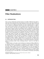
We have already discussed one structure employed to implement this algorithm
in Chapter 5, and because the coefficients of the multipliers in it are directly
available as the coefficients h(n) in H(z), it is called the direct form I structure
and is shown in Figure 6.1.
Whenever we have a structure to implement an FIR or an IIR filter, an equiv-
alent structure can be obtained as its transpose by the following operations:
1. Interchanging the input and the output nodes
2. Replacing adders by pickoff nodes and vice versa
3. Reversing all paths
Using these operations, we get the transpose of the structure of Figure 6.1
as Figure 6.2. This is known as direct form II structure; remember that this
(direct form II) structure will be called direct form I transposed structure in the
next chapter.
X(z)
z
−1
z
−1
z
−1
z
−1
Y(z)
h(0) h(1) h(2) h(3)
h(4)
Σ
Σ
Σ
Σ
Figure 6.1 Direct form I of an FIR filter.
306
FILTER REALIZATIONS
h(4) h(3) h(2) h(1) h(0)
Y(z)
ΣΣΣΣ
z
−1
z
−1
z
−1
z
−1
X(z)
Figure 6.2 Direct form II of an FIR filter.
Example 6.2: Cascade Form
If we have an FIR filter of high order, it may be realized as a cascade of FIR
filters of lower order, preferably as second-order filters when the order is even or
the cascade of second-order filters and one first-order filter when the order is odd.
We factorize the given FIR filter function H(z) =
M
n=0
h(n)z
−n
in the form
H(z) =
⎧
⎪
⎪
⎪
⎪
⎨
⎪
⎪
⎪
⎪
⎩
h(0)
M/2
m=1
1 + h(1m)z
−1
+ h(2m)z
−2
when M is even
h(0)
(1 + h(10)z
−1
)
(M−1)/2
m=1
1 + h(1m)z
−1
+ h(2m)z
−2
when M is odd
(6.6)
A cascade realization of this equation when M = 5 is shown in Figure 6.3, and
its transpose is shown in Figure 6.4.
X(z)
h(0)
Σ
Σ
Σ
Σ
Σ
z
−1
z
−1
z
−1
z
−1
z
−1
h(10)
h(11)
h(21)
h(22)
h(12)
Y(z)
Figure 6.3 Cascade connection of an FIR filter.
FIR FILTER REALIZATIONS
307
Σ
Σ
Σ
z
−1
z
−1
z
−1
X(z)
h(10)
h(22)
h(12)
Σ
Σ
z
−1
z
−1
h(21)
h(11)
h(0)
Y(z)
Figure 6.4 Transpose of the cascade connection shown in Figure 6.3.
Example 6.3: Polyphase Form
This realization is based on the polyphase decomposition of the FIR transfer
function and is illustrated by choosing the following example:
H
1
(z) = h(0) + h(1)z
−1
+ h(2)z
−2
+ h(3)z
−3
+ h(4)z
−4
+ h(5)z
−5
+ h(6)z
−6
+ h(7)z
−7
+ h(8)z
−8
(6.7)
This can be expressed as the sum of two subfunctions, shown below:
H
1
(z) =
h(0) + h(2)z
−2
+ h(4)z
−4
+ h(8)z
−8
+
h(1)z
−1
+ h(3)z
−3
+ h(5)z
−5
+ h(7)z
−7
=
h(0) + h(2)z
−2
+ h(4)z
−4
+ h(8)z
−8
+ z
−1
h(1) + h(3)z
−2
+ h(5)z
−4
+ h(7)z
−6
(6.8)
Let us denote A
0
(z) =
h(0) + h(2)z
−2
+ h(4)z
−4
+ h(8)z
−8
and
A
1
(z) =
h(1)z
−1
+ h(3)z
−3
+ h(5)z
−5
+ h(7)z
−7
= z
−1
h(1) + h(3)z
−2
+ h(5)z
−4
+ h(7)z
−6
Since the polynomials in the square brackets contain only even-degree terms,
we denote A
0
(z) = A
0
(z
2
) and A
1
(z) = z
−1
A
1
(z
2
). Hence we express H
1
(z) =
A
0
(z
2
) + z
−1
A
1
(z
2
). A block diagram showing this realization is presented in
Figure 6.5(a), where the two functions A
0
(z
2
) and A
1
(z
2
) are subfilters connected
in parallel.
308
FILTER REALIZATIONS
X(z)
z
−1
A
0
(z
2
)
A
1
(z
2
)
(a)(b)
z
−1
z
−1
Y(z)
Y(z)
Σ
Σ
Σ
X(z)
B
0
(z
3
)
B
1
(z
3
)
B
2
(z
3
)
Figure 6.5 Polyphase structures of FIR filters.
X(z)
h(0)
h(2)
h(4)
h(6)
h(8)
Y(z)
Σ
Σ
Σ
Σ
h(7)
h(5)
h(3)
h(1)
z
−2
z
−2
z
−1
z
−2
z
−2
Figure 6.6 Polyphase realization of an FIR filter H
1
(z).
FIR FILTER REALIZATIONS
309
These filters can be realized in either the direct form I or direct form II as
described earlier and illustrated in Figures 6.1 and 6.2, respectively. But there
would be 8 unit delays in building A
0
(z) and 7 unit delays in z
−1
A
1
(z),which
adds up to 15 unit delay elements. We prefer to realize a circuit that would
require a minimum number of unit delays that is equal to the order of the filter.
A realization that contains the minimum number of delays is defined as a canonic
realization. To reduce the total number of delays to 8, we cause the two subfilters
to share the unit delays in order to get a canonic realization. Such a circuit
realization is shown in Figure 6.6.
Example 6.4
Consider the same example and decompose (6.7) as the sum of three terms:
H(z) =
h(0) + h(3)z
−3
+ h(6)z
−6
+ z
−1
h(1) + h(4)z
−3
+ h(7)z
−6
+ z
−2
h(2) + h(5)z
−3
+ h(8)z
−6
= B
0
(z
3
) + z
−1
B
1
(z
3
) + z
−2
B
2
(z
3
) (6.9)
A block diagram for implementing this decomposition is shown in Figure 6.5b. A
canonic realization of (6.9) is shown in Figure 6.7 and its transpose in Figure 6.8,
each of which uses 8 unit delay elements. The FIR filter of order 8 chosen
in (6.7) can be decomposed as the sum of four subfilters in the form H(z) =
C
0
(z
4
) + C
1
(z
4
) + C
2
(z
4
) + C
3
(z
4
) and can be realized by a canonic circuit.
In general, an FIR function of order N (i.e. h(n) = 0forn>N)canbe
decomposed in the polyphase form with M subfilters connected in parallel as
follows
H(z) =
M−1
m=0
z
−m
E
m
(z
M
) (6.10)
where
E
m
(z) =
(N +1)/M
n=0
h(Mn + m)z
−n
(6.11)
6.2.1 Lattice Structure for FIR Filters
FIR filters can be realized in structures called lattice structures shown later in
the chapter in Figure 6.17a and its transpose, in Figure 6.17b—for an example
of a third-order filter. We will describe the design of these structures using a
MATLAB function in Section 6.5.
310
FILTER REALIZATIONS
Σ Σ Σ
z
−1
z
−3
z
−3
z
−1
X(z)
Y(z)
h(0)
h(3)
h(6)
h(1)
h(7)
h(4)
h(8)
h(5)
h(2)
Figure 6.7 Polyphase structure of an FIR filter function H
2
(z).
6.2.2 Linear Phase FIR Filter Realizations
When the FIR filter has a linear phase, its coefficients are symmetric or antisym-
metric, and hence the number of multipliers is reduced by almost half. For the
symmetric FIR filter of order N , the samples of the unit impulse response that
are the same as the multiplier coefficients satisfy the condition h(n) = h(N − n)
and it known as a type I FIR filter. The FIR filter with antisymmetric coefficients
satisfies the condition h(n) =−h(N − n) and is known as the type II FIR filter.
Example 6.5
Let us consider the example of a type I FIR filter, of order N = 6:
H
3
(z) = h(0) + h(1)z
−1
+ h(2)z
−2
+ h(3)z
−3
+ h(4)z
−4
+ h(5)z
−5
+ h(6)z
−6
(6.12)
= h(0) + h(1)z
−1
+ h(2)z
−2
+ h(3)z
−3
+ h(2)z
−4
+ h(1)z
−5
+ h(0)z
−6
= h(0)(1 + z
−6
) + h(1)(z
−1
+ z
−5
) + h(2)(z
−2
+ z
−4
) + h(3)z
−3
(6.13)
By sharing the multipliers, we get the realization shown in Figure 6.9, which
uses only four multipliers. It is still a canonic realization that uses six delay
elements.
FIR FILTER REALIZATIONS
311
X(z)
z
−3
z
−1
z
−1
z
−3
h(2)
h(5)
h(8)
h(7)
h(4)
h(1)
h(6)
h(3)
h(0)
Y(z)
Σ
Σ
ΣΣ
Σ
Figure 6.8 Transpose of the polyphase structure shown in Figure 6.7.
z
−1
z
−1
z
−1
z
−1
z
−1
z
−1
X(z)
h(1) h(2) h(3)
Y(z)
Σ
Σ
Σ
Σ
h(0)
ΣΣ
Figure 6.9 Direct-form structure of type I linear phase FIR filter function H
3
(z).
312
FILTER REALIZATIONS
X(z)
z
−1
z
−1
z
−1
z
−1
z
−1
h(1)
h(2)
h(3)
Y(z)
z
−1
z
−1
Σ
Σ
Σ
Σ
Σ
Σ
Σ
h(0)
Figure 6.10 Direct-form structure of type II linear phase FIR filter function H
4
(z).
Example 6.6
If we consider a type II FIR filter of order 7, its transfer function is given by
H
4
(z) = h(0) + h(1)z
−1
+ h(2)z
−2
+ h(3)z
−3
+ h(3)z
−4
+ h(2)z
−5
+ h(1)z
−6
+ h(0)z
−7
(6.14)
= h(0)(1 + z
−7
) + h(1)(z
−1
+ z
−6
) + h(2)(z
−2
+ z
−5
)
+ h(3)(z
−3
+ z
−4
) (6.15)
This is realized by the canonic circuit shown in Figure 6.10, thereby reducing
the total number of multipliers from 7 to 4. Similar cost saving is achieved in
the realization of FIR filters with antisymmetric coefficients.
6.3 IIR FILTER REALIZATIONS
In constructing several equivalent structures of an FIR filter, we used the direct-
form decomposition of the filter transfer function as the product of second-order
sections connected in cascade, polyphase decomposition, and transpose for each
structure obtained by them. We used the symmetry of the coefficients of linear
phase FIR filters to reduce the number of delay elements. We can also generate
their transpose forms. Using similar strategies, in this section we present several
structures for the IIR filters.
IIR FILTER REALIZATIONS
313
Example 6.7: Direct Forms
The transfer function (6.1) of an IIR filter is the ratio of a numerator polynomial
to a denominator polynomial. First we decompose it as the product of an all-pole
function H
1
(z) and a polynomial H
2
(z)
H(z) =
M
n=0
b(n)z
−n
1 +
N
n=1
a(n)z
−n
(6.16)
= H
1
(z)H
2
(z) =
1
1 +
N
n=1
a(n)z
−n
M
n=0
b(n)z
−n
(6.17)
and construct a cascade connection of an FIR filter H
2
(z) and the all-pole IIR
filter H
1
(z). Again we select an example to illustrate the method. Let H
2
(z) =
b
0
+ b(1)z
−1
+ b(2)z
−2
+ b(3)z
−3
and
H
1
(z) =
1
1 + a(1)z
−1
+ a(2)z
−2
+ a(3)z
−3
The realization of H
1
(z) in direct form I is shown in Figure 6.11 as the filter
connected in cascade with the realization of the FIR filter H
2
(z) also in direct
form I structure. The structure for the IIR filter is also called a direct form
I because the gain constants of the multipliers are directly available from the
coefficients of the transfer function.
We note that H
1
(z) = V(z)/X(z) and H
2
(z) = Y(z)/V(z). We also note that
the signals at the output of the three delay elements of the filter for H
1
(z) are
X(z)
V(z)
b(0)
b(1)
b(2)
b(3)
Y(z)
−a(1)
−a(2)
−a(3)
Σ
Σ
Σ
Σ
Σ
Σ
v
(n−1)
v
(n−1)
v
(n−2)
v
(n−2)
v
(n−3)
v
(n−3)
z
−1
z
−1
z
−1
z
−1
z
−1
z
−1
Figure 6.11 Direct form I of an IIR filter.
314
FILTER REALIZATIONS
X(z)
Y(z)
Σ
Σ
Σ
Σ
Σ
Σ
−a(3)
−a(2)
−a(1)
b(0)
b(1)
b(2)
b(3)
z
−1
z
−1
z
−1
Figure 6.12 Direct form II structure of an IIR filter.
the same as those at the output of the three delay elements of filter H
2
(z). Hence
we let the two circuits share one set of three delay elements, thereby reducing
the number of delay elements. The result of merging the two circuits is shown
in Figure 6.12 and is identified as the direct form II realization of the IIR filter.
Its transpose is shown in Figure 6.13. Both of them use the minimum number
of delay elements equal to the order of the IIR filter and hence are canonic
realizations.
The two filters realizing H
1
(z) and H
2
(z) can be cascaded in the reverse order
[i.e., H(z) = H
2
(z)H
1
(z)], and when their transpose is obtained, we see that
the three delay elements of H
2
(z) can be shared with H
1
(z), and thus another
realization identified as direct form I as well as its transpose can be obtained.
Example 6.8: Cascade Form
The filter function (6.16) can be decomposed as the product of transfer functions
in the form
H(z) =
N
1
(z)N
2
(z) ···N
K
(z)
D
1
(z)D
2
(z)D
3
(z) ···D
K
(z)
(6.18)
=
N
1
(z)
D
1
(z)
N
2
(z)
D
2
(z)
N
3
(z)
D
3
(z)
···
N
K
(z)
D
K
(z)
(6.19)
= H
1
(z)H
2
(z)H
3
(z) ···H
K
(z) (6.20)
IIR FILTER REALIZATIONS
315
X(z)
Y(z)
b(0)
b(1)
b(2)
b(3)
Σ
Σ
Σ
Σ
−a(1)
−a(2)
−a(3)
z
−1
z
−1
z
−1
Figure 6.13 Direct form II transposed structure of an IIR filter.
where K = N/2whenN is even and the polynomials D
1
(z), D
2
(z), D
3
(z),and
so on are second-order polynomials, with complex zeros appearing in conjugate
pairs in any such polynomial. When N is odd, K = (N − 1)/2, and one of the
denominator polynomials is a first-order polynomial. The numerator polynomials
N
1
(z), N
2
(z), . . . may be first-order or second-order polynomials or a constant:
H(z) = H
0
1 + β
11
z
−1
1 + α
11
z
−1
k
1 + β
1k
z
−1
+ β
2k
z
−2
1 + α
1k
z
−1
+ α
2k
z
−2
(6.21)
Each of the transfer functions H
1
(z), H
2
(z),...,H
K
(z) is realized by the direct
form I or direct form II or their transpose structures and then connected in
cascade. They can also be cascaded in many other sequential order, for example,
H(z) = H
1
(z)H
3
(z)H
5
(z) . . . or H(z) = H
2
(z)H
1
(z)H
4
(z)H
3
(z)....
There are more choices in the realization of H(z) in the cascade connection in
addition to those indicated above. We can pair the numerators N
1
(z), N
2
(z), . . .
and denominators D
1
(z), D
2
(z), D
3
(z), . . . in many different combinations; in
other words, we can pair the poles and zeros of the polynomials in different
316
FILTER REALIZATIONS
ways. For example, we can define
H(z) =
N
1
(z)
D
2
(z)
N
2
(z)
D
3
(z)
N
3
(z)
D
4
(z)
···
N
K
(z)
D
1
(z)
=
N
2
(z)
D
1
(z)
N
3
(z)
D
4
(z)
N
4
(z)
D
3
(z)
···
N
k
(z)
D
2
(z)
=
N
K
(z)
D
1
(z)
N
2
(z)
D
3
(z)
N
4
(z)
D
2
(z)
···
and cascade them in many different orders.
So the number of realizations that can be obtained from a nominal IIR transfer
function is very large, in general. Besides the difference in the algorithms for
each of these realizations and the consequent effects of finite wordlength when the
coefficients of the filter and the signal samples are quantized to a finite number,
we have to consider the effect on the overall magnitude of the output sequence
and the need for scaling the magnitude of the output sequence at each stage of
the cascade connection and so on.
Example 6.9
Consider a simple example of an IIR filter as follows:
H(z) =
z(0.16z − 0.18)
(z − 0.2)(z + 0.1)(z + 0.4)(z
2
+ z + 0.5)
(6.22)
A few alternate forms of expressing this are given below:
H(z) =
1
(z
2
− 0.1z − 0.02)
(0.16z − 0.18)
(z
2
+ z + 0.5)
z
(z + 0.4)
(6.23)
=
z
(z + 0.4)
1
(z
2
− 0.1z − 0.02)
(0.16z − 0.18)
(z
2
+ z + 0.5)
=
(0.16z − 0.18)
(z
2
− 0.1z − 0.02)
z
(z
2
+ z + 0.5)
1
(z + 0.4)
=
z
(z
2
+ z + 0.5)
1
(z + 0.4)
(0.16z − 0.18)
(z
2
− 0.1z − 0.02)
(6.24)
Let us choose the last expression, (6.24), and rewrite it in inverse powers of z,
as given by
H(z
−1
) =
z
−1
1 + z
−1
+ 0.5z
−2
z
−1
(1 + 0.4z
−1
)
(0.16z
−1
− 0.18z
−2
)
(1 − 0.1z
−1
− 0.02z
−2
)
(6.25)
IIR FILTER REALIZATIONS
317
Σ
Σ
Σ
Σ
Σ
Σ
z
−1
z
−1
z
−1
z
−1
z
−1
−0.5
−0.4
−1
0.1
0.16
0.02
−0.18
X(z)
Y(z)
Figure 6.14 Cascade connection of an IIR filter.
One of the realizations used to implement this transfer function is shown in
Figure 6.14.
Instead of combining the factors (z − 0.2) and (z + 0.1) and getting (z
2
−
0.1z − 0.02), in the denominator of (6.22), we can combine (z − 0.2) and (z +
0.4) or (z + 0.1) and (z + 0.4) to generate new second-order polynomials and
select many pole–zero pairs and order of second-order sections connected in
cascade, adding to the many possible realizations of (6.22) in the cascade form.
The cascade connection of second-order sections, each realized in direct form II,
has been a popular choice for a long time and was investigated in great detail,
until other structures became known for their better performance with respect to
finite wordlength effects and practical applications.
Example 6.10: Parallel Form
The IIR transfer function can also be expanded as the sum of second-order
structures. It is decomposed into its partial fraction form, combining the terms
with complex conjugate poles together such that we have an expansion with real
coefficients only. We will choose the same example as (6.22) to illustrate this
form of realization.
One form of the partial fraction expansion of (6.22) is
H(z) =
5.31165z
z + 0.1
−
1.111z
z − 0.2
−
5.21368z
z + 0.4
+
1.1314z
2
− 0.15947z
z
2
+ z + 0.5
(6.26)
By combining (z + 0.1), (z − 0.2), (z + 0.4) in different pairs to get the cor-
responding denominator polynomials, we get the following expressions for the
318
FILTER REALIZATIONS
transfer function given above:
H(z) =
0.9797z
2
+ 1.6033z
z
2
+ 0.5z + 0.04
−
1.111z
z − 0.2
+
1.1314z
2
− 0.15947z
z
2
+ z + 0.5
(6.27)
=
−6.3248z
2
+ 0.5983z
z
2
+ 0.2z − 0.08
+
5.31165
z + 0.1
+
1.1314z
2
− 0.15947z
z
2
+ z + 0.5
(6.28)
=
4.200z
2
− 1.1173z
z
2
− 0.1z − 0.02
−
5.2134z
z + 0.4
+
1.1314z
2
− 0.15947z
z
2
+ z + 0.5
(6.29)
The three terms in these expressions are rewritten in inverse powers of z,and
any one of the IIR realizations (direct form or their transpose) is used to obtain
the circuit for each of them, and they are connected in parallel. Let us select the
last expression:
H(z) =
4.200z
2
− 1.1173z
z
2
− 0.1z − 0.02
−
5.2134z
z + 0.4
+
1.1314z
2
− 0.15947z
z
2
+ z + 0.5
=
4.200 − 1.117z
−1
1 − 0.1z
−1
− 0.02z
−2
−
5.2134
1 + 0.4z
−1
+
1.1314 − 0.1594z
−1
1 + z
−1
+ 0.5z
−2
(6.30)
Figure 6.15 shows a realization of the filter given by (6.30) in the parallel
form of connection, and by using the transpose of each sections, a new circuit
can be derived.
Another form of expanding the transfer function is the normal form of partial
fraction expansion, indicated by
H(z) =
R
1
z + 0.1
+
R
2
z − 0.2
+
R
3
z + 0.4
+
R
4
z + R
5
z
2
+ z + 0.5
=
R
1
z
−1
1 + 0.1z
−1
+
R
2
z
−1
1 − 0.2z
−1
+
R
3
z
−1
1 + 0.4z
−1
+
R
4
z
−1
+ R
5
z
−2
1 + z
−1
+ 0.5z
−2
(6.31)
which gives rise to additional structures.
So, the transfer function given by (6.22) was decomposed in the form of (6.25)
and realized by the cascade structure shown in Figure 6.14; it was decomposed in
the form of (6.30) and realized by the parallel connection in the structure shown
in Figure 6.15.
The algorithm used to implement the structure in Figure 6.14 is of the form
y
1
(n) = x(n) − y
1
(n − 1) − 0.5y
1
(n − 2)
y
2
(n) = y
1
(n) − 0.4y
2
(n − 1)
y
3
(n) = y
2
(n) + 0.1y
3
(n − 1) + 0.02y
3
(n − 2)
y(n) = 0.16y
3
(n − 1) − 0.18y
3
(n − 2)
IIR FILTER REALIZATIONS
319
Σ
Σ
Σ
Σ
Σ
Σ
Σ
Σ
X(z)
0.1
4.2
5.2134
0.02
−1.117
−0.4
−0.1594
−0.5
−1.0
1.1314
z
−1
z
−1
z
−1
z
−1
z
−1
Y(z)
Figure 6.15 Parallel connection of the IIR filter function H(z).
whereas the algorithm employed to implement the structure shown in Figure 6.15
has the form
y
1
(n) = x(n) + 0.1
y
1
(n − 1) + 0.02
y
1
(n − 2)
y
2
(n) = 4.2
y
1
(n) − 1.117
y
1
(n − 1)
y
3
(n) = x(n) − 0.4
y
3
(n − 1)
y
4
(n) = x(n) −
y
4
(n − 1) − 0.5
y
4
(n − 2)
y
5
(n) = 1.1314
y
4
(n) − 0.1594
y
4
(n − 1)
y(n) =
y
2
(n) + 5.2134
y
3
(n) +
y
5
(n)
Remember that under ideal conditions both algorithms give the same output
for a given input signal and the two structures realize the same transfer function
(6.22). But when the two algorithms have to be programmed and implemented
by hardware devices, the results would be very different and the accuracy of
320
FILTER REALIZATIONS
the resulting output, the speed of the execution, and the throughput, and other
factors would depend not only on the finite wordlength but also on so many
other factors, including the architecture of the DSP chip, program instructions
per cycle, and dynamic range of the input signal. We will discuss these factors
in a later chapter.
6.4 ALLPASS FILTERS IN PARALLEL
Next in importance is the structure shown in Figure 6.16. The transfer function
G(z) = Y(z)/X(z) is given by
1
2
[A
1
(z) + A
2
(z)], where A
1
(z) and A
2
(z) are
the allpass filters connected in parallel. But in this figure, there is another trans-
fer function, H(z) = V(z)/X(z), which is given by H(z) =
1
2
[A
1
(z) − A
2
(z)].
The structure shown in Figure 6.16 is also called the lattice structure or lattice-
coupled allpass structure by some authors. A typical allpass filter function is of
the form
A(z) =
N(z)
D(z)
=±
a
n
+ a
n−1
z
−1
+ a
n−2
z
−1
+···+a
1
z
−n+1
+ a
0
z
−n
a
0
+ a
1
z
−1
+ a
2
z
−2
+···+a
n−1
z
−n+1
+ a
n
z
−n
(6.32)
which shows that the order of the coefficients in the numerator is the reverse of
that in the denominator, when both the numerator and denominator polynomial
are expressed in descending powers of z. Equation (6.32) can be expressed in
another form as
A(z) =
z
−n
(a
0
+ a
1
z + a
2
z
2
+···+a
n−1
z
n−1
+ a
n
z
n
)
a
0
+ a
1
z
−1
+ a
2
z
−2
+···+a
n−1
z
−n+1
+ a
n
z
−n
=
z
−n
D(z
−1
)
D(z)
(6.33)
The zeros of the numerator polynomial D(z
−1
) are the reciprocals of the zeros
of the denominator D(z), and therefore the numerator polynomial D(z
−1
) is the
mirror image polynomial of D(z).
When the allpass filter has all its poles inside the unit circle in the z plane, it is
a stable function and its zeros are outside the unit circle as a result of the mirror
X(z)
A
1
(z)
A
1
(z)
Σ
Σ
1/2
1/2
−1
Y(z)
V(z)
Figure 6.16 Two allpass filters in parallel (lattice-coupled allpass structure).
ALLPASS FILTERS IN PARALLEL
321
image symmetry. Therefore a stable, allpass filter function is a non–minimum
phase function.
Letting a
0
= 1, we get the magnitude response of this filter to be a constant at
all frequencies, because the numerator is the complex conjugate of the denom-
inator. Since this filter transmits all frequencies with the same gain, it is called
an allpass filter:
A(e
jω
)
=
1 + a
1
e
jω
+ a
2
e
j2ω
+···+a
n
e
jnω
1 + a
1
e
−jω
+ a
2
e
−j2ω
+···+a
n
e
−jnω
= 1 (6.34)
But the phase response (and the group delay) is dependent on the coeffi-
cients of the allpass filter. We know that the phase response filter designed
to approximate a specified magnitude response is a nonlinear function of ω,
and therefore its group delay is far from a constant value. When an allpass fil-
ter is cascaded with such a filter, the resulting filter has a frequency response
H
1
(e
jω
)A(e
jω
) =
H
1
(e
jω
)A(e
jω
)
e
j[θ(ω)+φ(ω)]
=
H
1
(e
jω
)
e
j[θ(ω)+φ(ω)]
.Sothe
magnitude response does not change when the IIR filter is cascaded with an all-
pass filter, but its phase response θ(ω) changes by the addition of the phase
response φ(ω) contributed by the allpass filter. The allpass filters A(z) are there-
fore very useful for modifying the phase response (and the group delay) of filters
without changing the magnitude of a given IIR filter H
1
(z), when they are cas-
caded with H
1
(z). However, the method used to find the coefficients of the allpass
filter A(z) such that the group delay of H
1
(z)A(z) is a very close approximation
to a constant in the passband of the filter H
1
(z) poses a highly nonlinear problem,
and only computer-aided optimization has been utilized to solve this problem.
Normally IIR filters are designed from specifications for its magnitude only, and
its group delay is far from a linear function of frequency. There are many appli-
cations that call for a constant group delay or a linear phase response, and in
such cases, the filters are cascaded with an allpass filter that does not affect its
magnitude—except by a constant—but is designed such that it compensates for
the phase distortion of the IIR filter. Allpass filters designed for this purpose are
cascaded with the IIR filters and are known as delay equalizers.
An important property of allpass filters is that if the coefficients change in
wordlength, the magnitude response of an allpass filter at all frequencies does
not change. Recall that a second-order allpass filter was analyzed in Chapter 2,
and that if the transfer function of an allpass filter is of a higher order, it can
be realized by cascading second-order filters and possibly one first-order allpass
filter. We illustrate a few more structures that realize first-order allpass trans-
fer functions as well as second-order allpass functions later in the chapter, in
Figures 6.23 and 6.24.
Let us assume that the two allpass filters shown in Figure 6.16 are of order
(N − r) and r, respectively, and are given by
A
1
(z) =
z
−(N −r)
D
1
(z
−1
)
D
1
(z)
(6.35)
322
FILTER REALIZATIONS
and
A
2
(z) =
z
−r
D
2
(z
−1
)
D
2
(z)
(6.36)
Substituting them in G(z) =
1
2
[A
1
(z) + A
2
(z)]andH(z) =
1
2
[A
1
(z) − A
2
(z)],
we get
G(z) =
1
2
z
−(N −r)
D
1
(z
−1
)D
2
(z) + z
−r
D
2
(z
−1
)D
1
(z)
D
1
(z)D
2
(z)
(6.37)
and
H(z) =
1
2
z
−(N −r)
D
1
(z
−1
)D
2
(z) − z
−r
D
2
(z
−1
)D
1
(z)
D
1
(z)D
2
(z)
(6.38)
If we express them in the form as
G(z) =
P(z)
D(z)
=
N
n=0
p
n
z
−n
D(z)
(6.39)
and
H(z) =
Q(z)
D(z)
=
N
n=0
q
n
z
−n
D(z)
(6.40)
then it can be shown that the following conditions are satisfied by (6.37) and
(6.38).
Property 6.1 P(z
−1
) = z
N
P(z). Hence p
n
= p
N −n
, that is, the coefficients of
P(z) are symmetric.
Property 6.2 Q(z
−1
) =−z
N
Q(z). Hence q
n
=−q
N −n
, that is, the coefficients
of Q(z) are antisymmetric.
Property 6.3 P(z)P(z
−1
) + Q(z)Q(z
−1
) = D(z)D(z
−1
). Hence
G(e
jω
)
2
+
H(e
jω
)
2
= 1 (6.41)
in other words, G(z) and H(z) are said to form a power complementary pair.
In the next chapter the structure for realizing G(e
jω
) will be termed a lattice-
coupled allpass filter and because of the property stated here, the structure for
realizing H(e
jω
) will be called a lattice-coupled allpass power complementary
filter.
ALLPASS FILTERS IN PARALLEL
323
Property 6.4
G(e
jω
)
=
1
2
e
jθ
1
(ω)
+ e
jθ
2
(ω)
=
1
2
1 + e
j(θ
1
(ω)−θ
2
(ω)
≤ 1 (6.42)
where A
1
(e
jω
) = e
jθ
1
(ω)
and A
2
(e
jω
) = e
jθ
2
(ω)
.
In the following analysis, we will assume that the four conditions described
above are satisfied by G(z) and H(z) and derive the results that they can be
obtained in the form G(z) =
1
2
[
A
1
(z) + A
2
(z)
]
and H(z) =
1
2
[
A
1
(z) − A
2
(z)
]
.
Consider Property 6.3: P(z)P(z
−1
) + Q(z)Q(z
−1
) = D(z)D(z
−1
).Using
Properties 6.1 and 6.2, we get
P(z)z
N
P(z)− z
N
Q(z)Q(z) = D(z)D(z
−1
) (6.43)
P
2
(z) − Q
2
(z) = D(z)z
−N
D(z
−1
) (6.44)
[
P(z)+ Q(z)
][
P(z)− Q(z)
]
= z
−N
D(z)D(z
−1
) (6.45)
From Properties 6.1 and 6.2, we have
P(z
−1
) + Q(z
−1
)
= z
N
[
P(z)− Q(z)
]
and therefore z
−N
P(z
−1
) + Q(z
−1
)
=
[
P(z)− Q(z)
]
, and we get
[
P(z)+ Q(z)
][
P(z)− Q(z)
]
= P
2
(z) − Q
2
(z) (6.46)
From (6.44), we have
P
2
(z) − Q
2
(z) = D(z)z
−N
D(z
−1
) (6.47)
[
P(z)+ Q(z)
]
z
−N
P(z
−1
) + Q(z
−1
)
= D(z)z
−N
D(z
−1
) (6.48)
Therefore
[
P(z)+ Q(z)
][
P(z)− Q(z)
]
= z
−N
D(z)D(z
−1
) (6.49)
This shows that the zeros of
[
P(z)− Q(z)
]
are reciprocals of the zeros of
[
P(z)+ Q(z)
]
.
It has been found that the Butterworth, Chebyshev, and elliptic lowpass filters
of odd order satisfy the four properties described above. We know from Chapter 4
that their transfer function G(z) obtained from the bilinear transformation of
the analog lowpass prototype filters has no poles on the unit circle. In other
words, the zeros of D(z) are within the unit circle, and therefore the zeros of
D(z
−1
) are outside the unit circle, because they are the reciprocals of the zeros
of D(z). From (6.49) we see that the zeros of
[
P(z)+ Q(z)
]
and
[
P(z)− Q(z)
]
cannot lie on the unit circle. Let us assume that
[
P(z)+ Q(z)
]
has r zeros
324
FILTER REALIZATIONS
z
k
(k = 1, 2, 3,...,r) that are inside the unit circle and (N − r) zeros z
j
(j =
r + 1,r + 2,...,N) that are outside the unit circle. Therefore
[
P(z)− Q(z)
]
has r zeros z
−1
k
(k = 1, 2, 3,...,r) outside the unit circle and (N − r) zeros z
−1
j
(j = r + 1,r + 2,...,N) inside the unit circle. From (6.49), we can therefore
assume that D(z) that has all its zeros inside the unit circle is of the form
D(z) =
⎡
⎣
r
k=1
(1 − z
−1
z
k
)
N
j =r+1
(1 − z
−1
z
−1
j
)
⎤
⎦
(6.50)
and
[
P(z)+ Q(z)
][
P(z)− Q(z)
]
= z
−N
D(z)D(z
−1
)
=
⎡
⎣
r
k=1
(1 − z
−1
z
k
)
N
j =r+1
(1 − z
−1
z
−1
j
)
⎤
⎦
×
⎡
⎣
r
k=1
(z
−1
− z
k
)
N
j =r+1
(z
−1
− z
−1
j
)
⎤
⎦
(6.51)
Thus we identify
P(z)+ Q(z) = α
r
k=1
(1 − z
−1
z
k
)
N
j =r+1
(z
−1
− z
−1
j
) (6.52)
P(z)− Q(z) =
1
α
r
k=1
(z
−1
− z
k
)
N
j =r+1
(1 − z
−1
z
−1
j
) (6.53)
Then
G(z) + H(z) =
P(z)+ Q(z)
D(z)
= α
N
j =r+1
z
−1
− z
−1
j
1 − z
−1
z
−1
j
= αA
1
(z) (6.54)
G(z) − H(z) =
P(z)− Q(z)
D(z)
=
1
α
r
k=1
z
−1
− z
k
1 − z
−1
z
k
=
1
α
A
2
(z) (6.55)
But from the power complementary property, we must have α
2
= 1. Therefore,
α = 1, so that
G(z) =
1
2
[
A
1
(z) + A
2
(z)
]
(6.56)
H(z) =
1
2
[
A
1
(z) − A
2
(z)
]
(6.57)
So we have proved that when G(z) is a Butterworth, Chebyshev, or elliptic
lowpass filter of odd order (which satisfy the four properties listed above), we
ALLPASS FILTERS IN PARALLEL
325
can decompose G(z) as the sum of two allpass functions, A
1
(z)/2andA
2
(z)/2.
Once we have derived the two allpass functions, we easily obtain H(z) as the
difference of A
1
(z)/2andA
2
(z)/2 and realize it by the structure of Figure 6.16.
Because of the complementary power property, we see that H(z) realizes a
highpass filter.
6.4.1 Design Procedure
The procedure to find the poles and zeros of the two allpass filters from the
given Butterworth, Chebyshev, or elliptic lowpass filters of odd order is described
below. We have already pointed out that the transfer function G(z) = P (z)/D(z)
for these filters obtained from the corresponding analog prototype via the bilinear
transformation have all their poles inside the unit circle of the z plane. Their
magnitude response
G(e
jω
)
has a maximum value at ω = 0, which can be easily
obtained as the value of G(z) at z = 1. In order to satisfy Property 6.4, we have
to divide G(z) by G(e
j
) or multiply G(z) by a scaling factor k = D(1)/P (1) so
that
kG(e
jω
)
≤ 1 as the first step in the design procedure. Let us assume that
G(z) has already been scaled by k in our further discussion.
From (6.47), we write
Q
2
(z) = P
2
(z) − D(z)z
−N
D(z
−1
) (6.58)
We know the numerator polynomial P(z) and the denominator polynomial D(z)
of the filter function G(z), and hence we can compute the right side of the
Equation 6.58. Let us denote Q
2
(z) = Q(z)Q(z) as R(z) =
2N
n=0
r
n
z
−n
.The
coefficients of R(z) = Q(z)Q(z) are computed by convolution of the coefficients
of Q(z) with the coefficients of Q(z):
r
n
= q
n
∗ q
n
=
n
k=0
q
k
q
n−k
(6.59)
These coefficients can be computed recursively by the following algorithm:
q
0
=
√
r
0
(6.60)
q
1
=
r
1
2q
0
(6.61)
q
n
=
r
n
−
n−1
k=1
q
k
q
n−k
2q
0
, 2 ≤ n ≤ N (6.62)
But we need to compute q
n
for only n = 0, 1, 2,...,(N− 1)/2, since these
coefficients are antisymmetric and q
n
= 0whenn = (N + 1)/2.
When we have computed the coefficients q
n
and constructed the polyno-
mial Q(z) =
N
n=0
q
n
z
−n
,wegetP(z)+ Q(z), and now we factorize it to
find its N zeros. We identify the zeros inside the unit circle as the r poles
z
k
(k = 1, 2, 3,...,r) of A
2
(z). By reversing the coefficients of the polynomial
326
FILTER REALIZATIONS
having these zeros, we get the numerator of A
2
(z), which has the zeros at z
−1
k
.
We identify the zeros of P(z)+ Q(z) that are outside the unit circle as the
(N − r) zeros z
j
(j = r + 1,r + 2,...,N) of A
1
(z). By reversing the order of
the coefficients of the numerator polynomial having these zeros, we obtain the
denominator polynomial of A
1
(z).Ithas(N − r) zeros at z
−1
j
as shown in (6.54).
This completes the design procedure used to obtain A
1
(z) and A
2
(z) from G(z).
An example is worked out in Section 6.5.
6.4.2 Lattice– Ladder Realization
Another well-known realization of an IIR transfer function of the form (6.1) is
shown in Figure 6.19a, and is known as the lattice–ladder realization.Itisalso
called the autoregressive moving-average (ARMA) model in the literature on
speech processing, adaptive filters, and signal processing in general. When the
numerator of (6.1) is a constant, we have an all-pole model also known as the
autoregressive (AR) model, and the structure to realize a third-order AR model
is shown in Figure 6.19b, whereas when the denominator is a constant, we get
an FIR model called the moving-average (MA) model. The structure shown in
Figure 6.17a is the model for a third-order FIR filter function or the MA model,
and the structure in Figure 6.17b is its transpose. We do not present the theoreti-
cal analysis of lattice structures for these models as it is beyond the scope of this
book but explain the use of a MATLAB function
tf2latc
in the next section to
derive the structures. This function implements the theoretical procedure, and
for the ARMA model, it gives the N lattice parameters k
i
, i = 1, 2,...,N
and also the values of the N + 1 ladder coefficients v
i
, i = 0, 1,...,N.But
Σ
Σ
Σ Σ Σ
Σ
ΣΣ
Σ
ΣΣΣ
X(z)
K
1
K
1
K
2
K
3
K
3
K
2
Y(z)
V(z)
X(z)
U(z)
K
3
K
3
K
2
K
1
K
1
K
2
Y(z)
(a)
(b)
z
−1
z
−1
z
−1
z
−1
z
−1
z
−1
Figure 6.17 (a) Lattice structure for an FIR filter; (b) transpose of the lattice structure
for the FIR filter in (a).
REALIZATION OF FIR AND IIR FILTERS USING MATLAB
327
in Figure 6.19a, the value of the ladder coefficient v
5
happens to be zero for the
numerical example, and therefore the multiplier v
5
is zero. The lattice parameters
are also known as the reflection coefficients, and it has been shown that the poles
of the IIR filter function are inside the unit circle of the z plane if
|
k
i
|
≤ 1. So
this method is used to test whether an IIR filter is stable.
6.5 REALIZATION OF FIR AND IIR FILTERS USING MATLAB
Many of the computations involved in the realization of FIR and IIR filters as
presented in this chapter can be carried out by MATLAB functions. For example,
an FIR filter realization in the cascaded structure can be obtained by finding the
roots of the transfer function and then finding the second-order polynomials with
complex conjugate pair of the roots or a pair of two real zeros.
To find the roots of a polynomial H(z) =
N
n=0
b(n)z
−n
,weusetheMATLAB
function
R = roots(b)
where the vector
b = [b(0), b(1), b(2), ···
b(N)]
and
R
is the vector of the
N
roots. Choosing a pair of complex conju-
gate roots or a pair of real roots, we construct the second-order polynomials
using the MATLAB function
P
k
=poly(R
k
)
,where
R
k
is the list of two roots and
P
k
is the vector of the coefficients of the second-order polynomial. Of course, if
H(z) is an odd-order polynomial, one first-order polynomial with a single real
root will be left as a term in the decomposition of H(z).
Example 6.11
Using the MATLAB commands
b = [1.965 -3.202 4.435 -3.14 1.591 -0.3667];
R= roots(b)
we get the roots
0.2682 + 0.8986
i
0.2682 - 0.8986
i
0.3383 + 0.6284
i
0.3383 - 0.6284
i
0.4166
Then we continue
R1=[0.2682+0.8986*i 0.2682-0.8986*i];
P1=poly(R1)
P1=
1.0000 -0.5364 0.8794
R2=[0.3383+0.6284*i 0.3383-0.6284*i];
P2=poly(R2)