LRFD pre-stressed beam.mcd_04
Bạn đang xem bản rút gọn của tài liệu. Xem và tải ngay bản đầy đủ của tài liệu tại đây (66.03 KB, 17 trang )
LRFD pre-stressed beam.mcd
7/1/2003 55 of 71
max_d 1.5=max_d
length 12⋅
800
:=
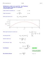
Max allowable deflection
Positive value indicates
an downward deflection
defl_p 0.948=defl_p
M5 lc⋅ 12⋅ 0.5⋅
0
sp 0.5⋅
j
M6
j
∑
=
−
Ec 1000⋅ Ic⋅
:=
Final Deflection
M6
ns
M4
ns
xr1
ns
⋅:=
Area of each block * range
M5
ns
M4
ns
∑
1
2
⋅:=
Determine reaction area
M4
ns
M3
ns
length⋅ 12⋅
1
sp
⋅:=
Area along each block
xr1
ns
j1
j
lc 12⋅
2
int j⋅−
int
2
−←
j 0 sp..∈for
j1
ns
:=
Define range for each point on moment curve
0 5 10 15 20
0
7.5
.
10
6
1.5
.
10
7
2.25
.
10
7
3
.
10
7
M3
ns
ns
M3
ns
disp3aa
ns
LLDFM⋅ 12000⋅:=
Define actual moment curve =
int 60=int
length
sp
12⋅:=
Length of each section =
lc 100=lc length:=
Length of section for calculations (ft) =
Deflections under Live Load (SL, max Positive),
These will be based on simple span Live Load Moments
I will use the M/(E*I) method
LRFD pre-stressed beam.mcd
7/1/2003 56 of 71
Deflections due to non-composite Dead Loads (DC)
I will calculate the deflection due to beam weight based on the initial strength (and modulus) of the beam. The slab
weight shall be applied to the final concrete strength.
n1 0 10..:=
w
bwt
12
:= w 0.069= ws
DLnc
12
:=
ws 0.087=
range for tenth points (in) =
range1
0
0.1
0.2
0.3
0.4
0.5
0.6
0.7
0.8
0.9
1.0
:= x
n1
range1
n1
length⋅ 12⋅:=
Deflection from self weight at tenth points (k*in) =
Db
n1
w x
n1
⋅
24 Inc⋅ Eci⋅
length 12⋅( )
3
2 length⋅ 12⋅ x
n1
( )
2
⋅− x
n1
( )
3
+
⋅:=
Deflection from Non-Composite
at tenth points (k*in) =
Ds
n1
ws x
n1
⋅
24 Inc⋅ Ec⋅
length 12⋅( )
3
2 length⋅ 12⋅ x
n1
( )
2
⋅− x
n1
( )
3
+
⋅:=
LRFD pre-stressed beam.mcd
7/1/2003 57 of 71
column 0 = span point
column 1 = self wt
column 2 = non-comp Defl
column 3 = rail deflection
column 4 = Total for Oklahoma curve
0 0.5 1
0
0.5
1
1.5
2
Db
n1
Ds
n1
range1
n1
disp
0 1 2
0
1
2
3
4
5
6
7
8
9
10
0 0 0
0.1 0.474 0.523
0.2 0.897 0.99
0.3 1.228 1.355
0.4 1.439 1.587
0.5 1.511 1.666
0.6 1.439 1.587
0.7 1.228 1.355
0.8 0.897 0.99
0.9 0.474 0.523
1 0 0
=
LRFD pre-stressed beam.mcd
7/1/2003 58 of 71
Shear Design, pre-stress method
LRFD 5.8.2.4 Except for slabs footings and culverts, transverse reinforcement shall be provided where
Vu 0.5 φ⋅ Vc Vp+( )⋅>
Vu = factored shear force
Vc = nominal resistance of concrete
Vp = component of the prestressing force in direction of the shear force
LRFD 5.8.2.5: Minimum transverse reinforcing
Av 0.0316 fcf⋅
bv S⋅
fy
⋅=
Av = area of transverse reinforcing within distance S
bv = width of web adjusted for the presence of ducts as specified in 5.8.2.9
S = spacing of transverse reinforcing
fy = yeild strength of transverse reinforcing
fcf = final concrete strength
LRFD 5.8.2.7: Maximum spacing of transverse reinforcing.
If Vu<0.125*fcf then: Smax = 0.8*dv<= 24 in
If Vu>=0.125*fcf then: Smax = 0.4*dv<= 12 in
Vu = the shear stress calculated in accordance with 5.8.2.9
dv = effective shear depth as defined in 5.8.2.9
LRFD 5.8.2.9: Shear stress in concrete
V
Vu φ Vp⋅−
φ bv⋅ dv⋅
=
bv = effective web width
dv = effective shear depth dv
Mn
As fy⋅ Aps fps⋅+
=
φ = resistance factor for shear 5.5.4.2
LRFD 5.8.3.3: The nominal shear resistance Vn shall be determined as the lesser of
Vn Vc Vs+ Vp+=
Vn 0.25 fcf⋅ bv⋅ dv⋅ Vp+=
for which
Vc 0.0316 β⋅ fcf⋅ bv⋅ dv⋅=
Vs
Av fy⋅ dv⋅ cot θ
( )
⋅
S
= this is as per commentary EQ C5.8.3.3.1
β = Factor as defined in article 5.8.3.4
θ = angle of inclination of diagonal compressive stresses as determined in 5.8.3.4
α = angle of inclination of transverse reinforcement to longitudinal axis
LRFD pre-stressed beam.mcd
7/1/2003 59 of 71
Mu
mp
43335.148=Mu
ns
max
Mu1
ns
Vu
ns
dv
ns
⋅
:=
Mu shall not be less than Vu*dv (k*in) =
Mu1
mp
43335.148=Mu1
ns
max
STI6
ns
STI7
ns
12⋅:=
Define factored moment (k*in) =
Vu
mp
244.729=Vu
ns
max
STI6v
ns
STI7v
ns
:=
Define factored shear (k) =
dv
mp
49.603=dv
ns
j
ns
0.9 de
ns
( )
⋅ 0.9 de
ns
⋅ 0.72 h ts+( )⋅>if
0.72 h ts+( )⋅ otherwise
←
j1
ns
de
ns
a
ns
0.5⋅−←
j
ns
j
ns
j1
ns
>if
j1
ns
otherwise
:=
Effective shear depth (in) =
de
mp
52.375=de
ns
h ts+ ecc
ns
−:=
Distance from top slab to CL.
prestressing (in) =
bv 6=bv bw:=
Width of web (in) =
mp 3:=
LRFD5.8.3.4.2: Use for the calculation of β and θ
εt
Mu
ns
dv
ns
Vu
ns
+ Vp
ns
− Aps
ns
fpo⋅−
Ep Aps
ns
⋅
=
εx
εt
2
=
Ac = area of concrete on the flexural tension side of the member (see fig 1)
Aps = area of prestressing steel on the flexural tension side of the member (see fig 1)
As = area of nonprestressed steel on the flexural tension side of the member at the section (fig 1)
fpo = for the usual levels of prestressing 0.7*fpu will be appropriate
Mu = factored moment taken as positive, but not taken less than Vu*dv
Vu = factored shear force taken as positive
LRFD pre-stressed beam.mcd
7/1/2003 60 of 71
disp
ns 9,
Smax
ns
:=disp
ns 7,
V
ns
:=disp
ns 5,
Mu
ns
:=disp
ns 3,
dv
ns
:=disp
ns 1,
bv:=
disp
ns 8,
r
ns
:=disp
ns 6,
Vp
ns
:=disp
ns 4,
Vu
ns
:=disp
ns 2,
de
ns
:=disp
ns 0,
x1
ns
:=
disp 0:=
Smax
mp
24=Smax
ns
min
0.8 dv
ns
⋅
24.0
V
ns
0.125 fcf⋅<if
min
0.4 dv
ns
⋅
12.0
otherwise
:=
Maximum spacing of transverse reinforcing (in) =
r
mp
0.114=r
ns
V
ns
fcf
:=
Ratio of V/fcf =
V
mp
0.914=
V
ns
Vu
ns
φ Vp
ns
⋅−
φ bv⋅ dv
ns
⋅
:=
Shear stress on the concrete (ksi) =
Vp
mp
0=Vp
ns
Ff
ns
sin angle
ns
π
180
⋅
⋅:=
angle
ns
0 harped "n"=if
atan
enc
0
enc
ceil sp 0.5⋅( )
−
length 12⋅ depress⋅
180
π
⋅ otherwise
:=
Component of the prestressing force
in direction of the shear force Vp (k) =
Fp
mp
950.739=Fp
ns
fpo ∆ft−
( )
Aps
ns
⋅:=
Use stress for vertical force (k) =
fpo 189=fpo 0.7 Strand_strength⋅:=
Calculate force "fpo" (ksi) =
φ 0.9:=
Resistance factor for concrete (5.5.4.2) =