Báo cáo y học: "Mechanical behaviour of standardized, endoskeleton-including hip spacers implanted into composite femurs"
Bạn đang xem bản rút gọn của tài liệu. Xem và tải ngay bản đầy đủ của tài liệu tại đây (1.94 MB, 7 trang )
Int. J. Med. Sci. 2009, 6
280
I
I
n
n
t
t
e
e
r
r
n
n
a
a
t
t
i
i
o
o
n
n
a
a
l
l
J
J
o
o
u
u
r
r
n
n
a
a
l
l
o
o
f
f
M
M
e
e
d
d
i
i
c
c
a
a
l
l
S
S
c
c
i
i
e
e
n
n
c
c
e
e
s
s
2009; 6(5):280-286
© Ivyspring International Publisher. All rights reserved
Research Paper
Mechanical behaviour of standardized, endoskeleton-including hip spacers
implanted into composite femurs
T. Thielen
1
, S. Maas
1
, A. Zuerbes
1
, D. Waldmann
1
, K. Anagnostakos
2
, J. Kelm
2, 3
1. Research Unit in Engineering Sciences, University of Luxembourg, Luxembourg
2. Klinik für Orthopädie und Orthopädische Chirurgie, Universitätsklinikum des Saarlandes, Homburg / Saar, Germany
3. Chirurgisch-Orthopädisches Zentrum, Illingen / Saar, Germany
Correspondence to: Dipl.-Ing. (MSc) Thomas Thielen, Université du Luxembourg, Faculté des Sciences, de la Technique et
de la Communication, 6, rue Richard Coudenhove-Kalergi, L-1359 Luxembourg-Kirchberg. Phone: (+352) 46 66 44 5422; Fax:
(+352) 46 66 44 5620;
Rec
eived: 2009.08.01; Accepted: 2009.09.02; Published: 2009.09.03
Abstract
Two-stage reconstruction using an antibiotic loaded cement spacer is the preferred treat-
ment method of late hip joint infections. Hip spacers maintain stability of the joint and length
of the limb during treatment period. However, as the material strength of bone cement
(PMMA) is limited, spacer fractures led to serious complications in the past. This study in-
vestigated the load capacity of custom made hip spacers, developed at the ‘Klinik für Or-
thopädie und Orthopädische Chirurgie’ (Universitätsklinikum des Saarlandes, Homburg /
Saar, Germany), and implanted into composite femurs. In a quasi-static test, non-reinforced
spacers tolerated hip joint loads of about 3000 N, whereas reinforced spacers with tita-
nium-grade-two endoskeletons doubled this load up to 6000 N. Even for cyclic loading,
endoskeleton-including hip spacers tolerated loads of >4500 N with 500,000 load cycles.
Thus, an endoskeleton-including spacer should provide a mobile and functional joint through
the treatment course. A generated FE-model was used to determine the fracture stresses
and allows for further sensitivity analysis.
Key words: Spacer, Fracture, Infection, Bone cement, Endoskeleton
Introduction
The application of a spacer made of antibiotic
impregnated bone cement (PMMA) is a recom-
mended treatment method in the two-stage reim-
plantation procedure for late hip joint infections [1-5].
An antibiotic-impregnated cement spacer delivers a
high-dose concentration of local antibiotics to the in-
fected area, prevents soft tissue shortening and pro-
vides better function than a resection arthroplasty.
Although few commercially made, pre-formed hip
spacers are available, they lack adaptability [6, 7]. The
‘Klinik für Orthopädie und Orthopädische Chirurgie’
(Universitätsklinikum des Saarlandes, Homburg /
Saar, Germany) developed therefore a special
moulding form whereby a standardized, antibi-
otic-loaded cement spacer adapted to patient infection
can be formed during surgery [8-10]. As spacers are
capable to eradicate the infections, complications in-
clude fractures of spacers [11-13]. This study evaluates
therefore the strength of non-reinforced spacers and
spacers having an adapted endoskeleton when im-
planted into composite femurs.
Materials and Methods
Laboratory test
The bone cement Palacos® (Merck, Darmstadt,
Germany) was used for our spacers. It is distin-
guished because of its very high antibiotic release rate
Int. J. Med. Sci. 2009, 6
281
with comparative high material strength [14-16]. To
form a single spacer (head diameter, 50 mm; stem
length, 100 mm; surface area, 13,300 mm
2
), a mixture
of 80 g powder into 40 ml liquid was hand mixed
without vacuum. In order to keep variety as low as
possible, plain cement, i.e. cement without antibiotic
has been used for mechanical testing. Spacer were
formed into a 2-parts molding form out of polyoxy-
methylene (POM) [17] (Fig.1). After filling but before
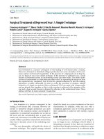
consolidation, an endoskeleton made of tita-
nium-grade-two (Euro-Titan AG, Solingen, Germany)
could be centered into the cement spacer for rein-
forcement (Fig. 2).
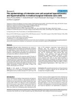
Figure 1: Two components of Palacos®: powder (poly-
mer) and liquid (monomer) are mixed in a ratio of 2g : 1ml.
After mixing, the compound is filled into a casting mould of
polyoxymethylene (POM) to form the spacer.
Figure 2: Spacer with endoskeleton of titanium-grade-two
and distance pieces for centering
Titanium grade two was chosen because of its
biocompatibility, very high strength and ductility. For
testing, non-reinforced and reinforced spacers were
implanted into fourth generation composite femurs
(Sawbones AB, Malmö, Sweden) that had the femoral
head removed and canal reamed. As there is no
standardized protocol of testing the mechanical be-
haviour of a hip spacer available, the loading proce-
dure was defined following the recommendations of
the ISO 7206 standard for determination of fatigue
performance of hip stems [18]. The femurs were in-
Int. J. Med. Sci. 2009, 6
282
clined 10° in the frontal plane and 9° in the sagittal
plane and loaded using an INSTRON servo-hydraulic
testing machine (Instron, Darmstadt, Germany).
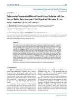
Loads are applied through the femoral head of the
spacer, where shear loads were eliminated by means
of a ball bearing cup (Fig. 3).
Figure 3: Test bed for an implanted spacer in a composite
femur on a servo-hydraulic cylinder test station (Instron,
PL10K). The femur is oriented at 9° in the sagittal plane and
10° in the frontal plane.
To keep friction as low as possible, the interface
between cup (POM, d = 120 mm) and spacer head
(PMMA) is furthermore lubricated (Shell 138 Retinax
CS 00). The loading rate of the quasi-static test was 20
N/s. Cyclical tested spacers were sinusoidally loaded
with a frequency of 5 Hz. Test abort was either failure
of the spacer or the femur. Three specimens were
tested in each test series.
Finite element model
Based on the laboratory tests, a finite element
model of spacer and femur was developed to analyze
stresses. The analysis was performed using ANSYS, a
FEA software (ANSYS Inc., Canonsburg, United
States). The standardized femur was used as a basis
for a finite element model of a composite femur [19].
An IGES file of the spacer with/without endoskeleton
was placed within the composite femur geometry.
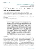
Meshing was conducted by the element 186, a hexa-
hedral solid element with quadratic displacement
behaviour (Fig. 4). For modeling the contact and
sliding between femur-spacer interface, CONTACT
174 and TARGET 170 elements were used. The mate-
rial properties are given in Table 1. The femur is
separated into two materials, cortical and cancellous
bone. The bone materials were assumed to be iso-
tropic and homogeneous (Table 1).
Table 1: List of material properties used for the analysis
Tension
Material
Young’s
modulus
[MPa]
Poisson’s
ratio (ν)
Yield
strength
[MPa]
Ultimate
strength
[MPa]
Compression
strength
[MPa]
Cortical
bone
16,000 0.26 - 107 154
Cancellous
bone
150 0.30 - - -
PMMA 2,500 0.35 - 35 85-100
Titanium
grade 2
110,000 0.34 R
p0,2
=325 430 430
Loading is similar to the laboratory tests, muscle
forces affecting the strain distribution on the femur
were neglected. The resultant hip force F
R
on the head
of the spacer can be resolved into:
F
x
= -cos 9° · sin 10° · F
R
= -0.17 · F
R
F
y
= -sin 9° · F
R
= -0.16 · F
R
F
z
= -cos 9° · cos 10° · F
R
= -0.97 · F
R
Figure 4: Finite element model of the spacer and femur
with meshing conducted by the solid element 186.
Int. J. Med. Sci. 2009, 6
283
Results
Laboratory test
Non-reinforced spacers, implanted into compos-
ite femur and quasi-static tested failed at F
R
= 2935 ±
322 N (Fig. 5). Spacer fracture occurred between 65 –
75 mm proximal to the spacer tip with the stem re-
maining in the medullary canal. Mechanical spalling
of a bone edge and tears on the proximal femur could
be observed after testing.
Spacers with an endoskeleton sustained loads up
to F
R
= 6270 ± 772 N and thus doubled the initial load
of non-reinforced spacers. Thereby loads exceeding
5000 – 6000 N caused a non-linear displacement be-
haviour of the reinforced spacer and resulted into
periprosthetic fractures of the proximal part of the
femur (Fig. 6). Fracture was of explosion type where
the spacer is loose and the fracture is inherently un-
stable. Reinforced spacer, cyclical loaded with 500,000
load cycles per load level could even resist maximum
loads between F
R
= 4700 – 4900 N before failure (Table
2).
Figure 5: Force – Displacement curves for the three non-reinforced spacers, quasi-static tested
Int. J. Med. Sci. 2009, 6
284
Figure 6: Force – Displacement curves for the three endoskeleton including spacers, quasi-static tested
Table 2: Results of three endoskeleton-including spacers
tested cyclically at different load ranges until fracture
lower cycle load -
upper cycle load [N]
load cycles condition
300 – 4500 500,000 passed Femur 1
300 – 4700 83,000 failure
300 – 4500 500,000 passed
300 – 4700 500,000 passed
Femur 2
300 – 4900 47,000 failure
300 – 4500 500,000 passed
300 – 4700 500,000 passed
Femur 3
300 – 4900 156,000 failure
Finite element model
The locations where the maximum stresses occur
on femur and spacer, respectively, are in accordance
to the fractures within the laboratory tests. The
maximum equivalent stresses on a non-reinforced
spacer reached the breakage stress (bending strength
of Palacos®: 50-60 MPa) at about F
R
= 3000 N (Fig. 7a).
In case of a reinforced spacer, the stresses are distrib-
uted according to the material stiffnesses, and, hence,
the endoskeleton carries the main load. The yield
strength of the titanium endoskeleton (325 MPa) is
reached at a hip joint load of F
R
= 5000 N (Fig. 7b).
However, as titanium-grade-two is a quite ductile
material, there are still plastic material reserves
available. The peak stresses on the femur located
above the lesser trochanter produce stress values of
120 MPa and 153 MPa, respectively, and should be
considered to indicate damage initiation events of
periprothetic fracture.