LVCore1 2010 eng
Bạn đang xem bản rút gọn của tài liệu. Xem và tải ngay bản đầy đủ của tài liệu tại đây (2.78 MB, 300 trang )
Na
ti o
No na
t fo l I n
r D str
i st um
ri b e n
uti ts
on
LabVIEW Core 1
Course Manual
TM
Course Software Version 2010
August 2010 Edition
Part Number 325290B-01
LabVIEW Core 1 Course Manual
Copyright
© 1993–2010 National Instruments Corporation. All rights reserved.
Under the copyright laws, this publication may not be reproduced or transmitted in any form, electronic or mechanical, including
photocopying, recording, storing in an information retrieval system, or translating, in whole or in part, without the prior written consent
of National Instruments Corporation.
National Instruments respects the intellectual property of others, and we ask our users to do the same. NI software is protected by
copyright and other intellectual property laws. Where NI software may be used to reproduce software or other materials belonging to
others, you may use NI software only to reproduce materials that you may reproduce in accordance with the terms of any applicable
license or other legal restriction.
For components used in USI (Xerces C++, ICU, HDF5, b64, Stingray, and STLport), the following copyright stipulations apply. For a
listing of the conditions and disclaimers, refer to either the USICopyrights.chm or the Copyrights topic in your software.
Xerces C++. This product includes software that was developed by the Apache Software Foundation ( />Copyright 1999 The Apache Software Foundation. All rights reserved.
ICU. Copyright 1995–2009 International Business Machines Corporation and others. All rights reserved.
HDF5. NCSA HDF5 (Hierarchical Data Format 5) Software Library and Utilities
Copyright 1998, 1999, 2000, 2001, 2003 by the Board of Trustees of the University of Illinois. All rights reserved.
b64. Copyright © 2004–2006, Matthew Wilson and Synesis Software. All Rights Reserved.
Stingray. This software includes Stingray software developed by the Rogue Wave Software division of Quovadx, Inc.
Copyright 1995–2006, Quovadx, Inc. All Rights Reserved.
STLport. Copyright 1999–2003 Boris Fomitchev
Trademarks
CVI, LabVIEW, National Instruments, NI, ni.com, the National Instruments corporate logo, and the Eagle logo are trademarks of
National Instruments Corporation. Refer to the Trademark Information at ni.com/trademarks for other National Instruments
trademarks.
The mark LabWindows is used under a license from Microsoft Corporation. Windows is a registered trademark of Microsoft
Corporation in the United States and other countries. Other product and company names mentioned herein are trademarks or trade
names of their respective companies.
Members of the National Instruments Alliance Partner Program are business entities independent from National Instruments and have
no agency, partnership, or joint-venture relationship with National Instruments.
Patents
For patents covering National Instruments products/technology, refer to the appropriate location: Help»Patents in your software,
the patents.txt file on your media, or the National Instruments Patent Notice at ni.com/patents.
Na
ti o
No na
t fo l I n
r D str
i st um
ri b e n
uti ts
on
Worldwide Technical Support and Product Information
ni.com
National Instruments Corporate Headquarters
11500 North Mopac Expressway Austin, Texas 78759-3504 USA Tel: 512 683 0100
Worldwide Offices
Australia 1800 300 800, Austria 43 662 457990-0, Belgium 32 (0) 2 757 0020, Brazil 55 11 3262 3599, Canada 800 433 3488,
China 86 21 5050 9800, Czech Republic 420 224 235 774, Denmark 45 45 76 26 00, Finland 358 (0) 9 725 72511,
France 01 57 66 24 24, Germany 49 89 7413130, India 91 80 41190000, Israel 972 3 6393737, Italy 39 02 41309277,
Japan 0120-527196, Korea 82 02 3451 3400, Lebanon 961 (0) 1 33 28 28, Malaysia 1800 887710, Mexico 01 800 010 0793,
Netherlands 31 (0) 348 433 466, New Zealand 0800 553 322, Norway 47 (0) 66 90 76 60, Poland 48 22 328 90 10,
Portugal 351 210 311 210, Russia 7 495 783 6851, Singapore 1800 226 5886, Slovenia 386 3 425 42 00,
South Africa 27 0 11 805 8197, Spain 34 91 640 0085, Sweden 46 (0) 8 587 895 00, Switzerland 41 56 2005151,
Taiwan 886 02 2377 2222, Thailand 662 278 6777, Turkey 90 212 279 3031, United Kingdom 44 (0) 1635 523545
For further support information, refer to the Additional Information and Resources appendix. To comment on National Instruments
documentation, refer to the National Instruments Web site at ni.com/info and enter the Info Code feedback.
Contents
Na
ti o
No na
t fo l I n
r D str
i st um
ri b e n
uti ts
on
Student Guide
A.
B.
C.
D.
E.
F.
NI Certification .....................................................................................................vii
Course Description ...............................................................................................viii
What You Need to Get Started .............................................................................ix
Installing the Course Software..............................................................................x
Course Goals.........................................................................................................xi
Course Conventions ..............................................................................................xii
Lesson 1
Setting Up Hardware
A.
B.
C.
D.
E.
F.
G.
DAQ Hardware .....................................................................................................1-2
Using DAQ Software............................................................................................1-9
Instrument Control ................................................................................................1-12
GPIB .....................................................................................................................1-12
Serial Port Communication...................................................................................1-14
Using Instrument Control Software ......................................................................1-16
Course Project.......................................................................................................1-18
Lesson 2
Navigating LabVIEW
A.
B.
C.
D.
E.
F.
G.
H.
I.
J.
Virtual Instruments (VIs)......................................................................................2-2
Parts of a VI ..........................................................................................................2-2
Starting a VI..........................................................................................................2-4
Project Explorer ....................................................................................................2-8
Front Panel ............................................................................................................2-13
Block Diagram ......................................................................................................2-21
Searching for Controls, VIs and Functions...........................................................2-30
Selecting a Tool ....................................................................................................2-32
Dataflow................................................................................................................2-39
Building a Simple VI ............................................................................................2-41
Lesson 3
Troubleshooting and Debugging VIs
A.
B.
C.
D.
E.
LabVIEW Help Utilities .......................................................................................3-2
Correcting Broken VIs..........................................................................................3-5
Debugging Techniques .........................................................................................3-6
Undefined or Unexpected Data.............................................................................3-13
Error Checking and Error Handling......................................................................3-13
© National Instruments Corporation
iii
LabVIEW Core 1 Course Manual
Contents
Lesson 4
Implementing a VI
Front Panel Design................................................................................................4-2
LabVIEW Data Types ..........................................................................................4-8
Documenting Code ...............................................................................................4-17
While Loops..........................................................................................................4-19
For Loops ..............................................................................................................4-23
Timing a VI...........................................................................................................4-27
Iterative Data Transfer ..........................................................................................4-28
Plotting Data .........................................................................................................4-32
Case Structures .....................................................................................................4-38
Na
ti o
No na
t fo l I n
r D str
i st um
ri b e n
uti ts
on
A.
B.
C.
D.
E.
F.
G.
H.
I.
Lesson 5
Relating Data
A. Arrays....................................................................................................................5-2
B. Clusters .................................................................................................................5-8
C. Type Definitions ...................................................................................................5-14
Lesson 6
Managing Resources
A.
B.
C.
D.
E.
F.
Understanding File I/O .........................................................................................6-2
Understanding High-Level File I/O ......................................................................6-4
Understanding Low-Level File I/O.......................................................................6-5
DAQ Programming...............................................................................................6-7
Instrument Control Programming .........................................................................6-10
Using Instrument Drivers......................................................................................6-12
Lesson 7
Developing Modular Applications
A. Understanding Modularity ....................................................................................7-2
B. Building the Icon and Connector Pane .................................................................7-4
C. Using SubVIs ........................................................................................................7-9
Lesson 8
Common Design Techniques and Patterns
A.
B.
C.
D.
Using Sequential Programming ............................................................................8-2
Using State Programming .....................................................................................8-5
State Machines ......................................................................................................8-5
Using Parallelism ..................................................................................................8-13
LabVIEW Core 1 Course Manual
iv
ni.com
Contents
Lesson 9
Using Variables
Parallelism ............................................................................................................9-2
Variables ...............................................................................................................9-4
Functional Global Variables .................................................................................9-14
Race Conditions ....................................................................................................9-17
Na
ti o
No na
t fo l I n
r D str
i st um
ri b e n
uti ts
on
A.
B.
C.
D.
Appendix A
Measurement Fundamentals
A. Using Computer-Based Measurement Systems....................................................A-2
B. Understanding Measurement Concepts ................................................................A-4
C. Increasing Measurement Quality ..........................................................................A-12
Appendix B
Additional Information and Resources
Glossary
Index
© National Instruments Corporation
v
LabVIEW Core 1 Course Manual
Na
ti o
No na
t fo l I n
r D str
i st um
ri b e n
uti ts
on
Student Guide
Na
ti o
No na
t fo l I n
r D str
i st um
ri b e n
uti ts
on
Thank you for purchasing the LabVIEW Core 1 course kit. You can begin
developing an application soon after you complete this course. This course
manual and the accompanying software are used in the three-day, hands-on
LabVIEW Core 1 course.
You can apply the full purchase of this course kit toward the corresponding
course registration fee if you register within 90 days of purchasing the kit.
Visit ni.com/training for online course schedules, syllabi, training
centers, and class registration.
A. NI Certification
The LabVIEW Core 1 course is part of a series of courses designed to build
your proficiency with LabVIEW and help you prepare for NI LabVIEW
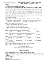
Associate Developer exam. The following illustration shows the courses
that are part of the LabVIEW training series. Refer to ni.com/training
for more information about NI Certification.
New User
Experienced User
Advanced User
LabVIEW Core 1*
LabVIEW Core 3*
Managing Software
Engineering in LabVIEW
Courses
LabVIEW Core 2*
LabVIEW OOP System Design
Advanced Architectures
in LabVIEW
Certifications
Certified LabVIEW
Associate Developer Exam
Certified LabVIEW
Developer Exam
Certified LabVIEW
Architect Exam
Other Courses
LabVIEW Instrument Control
LabVIEW FPGA
LabVIEW Connectivity
LabVIEW Machine Vision
Modular Instruments Series
LabVIEW Performance
LabVIEW Real-Time
LabVIEW DAQ and Signal Conditioning
*Core courses are strongly recommended to realize maximum productivity gains when using LabVIEW.
© National Instruments Corporation
vii
LabVIEW Core 1 Course Manual
Student Guide
B. Course Description
Na
ti o
No na
t fo l I n
r D str
i st um
ri b e n
uti ts
on
The LabVIEW Core 1 course teaches you programming concepts,
techniques, features, VIs, and functions you can use to create test
and measurement, data acquisition, instrument control, datalogging,
measurement analysis, and report generation applications. This course
manual assumes that you are familiar with Windows and that you have
experience writing algorithms in the form of flowcharts or block diagrams.
The course and exercise manuals are divided into lessons, described as
follows.
In the course manual, each lesson consists of the following:
•
An introduction that describes the purpose of the lesson and what
you will learn
•
A description of the topics in the lesson
•
A summary quiz that tests and reinforces important concepts and
skills taught in the lesson
In the exercise manual, each lesson consists of the following:
•
A set of exercises to reinforce those topics
•
Some lessons include optional and challenge exercise sections or
a set of additional exercises to complete if time permits
Note
For course and exercise manual updates and corrections, refer to ni.com/info
and enter the Info Code Core1.
Several exercises use one of the following National Instruments hardware
products:
•
A plug-in multifunction data acquisition (DAQ) device connected to
a DAQ Signal Accessory or BNC-2120 containing a temperature sensor,
function generator, and LEDs
•
A GPIB interface connected to an NI Instrument Simulator
If you do not have this hardware, you still can complete the exercises.
Alternate instructions are provided for completing the exercises without
hardware. Exercises that explicitly require hardware are indicated with
an icon, shown at left. You also can substitute other hardware for those
previously mentioned. For example, you can use a GPIB instrument in place
of the NI Instrument Simulator, or another National Instruments DAQ
device connected to a signal source, such as a function generator.
LabVIEW Core 1 Course Manual
viii
ni.com
Student Guide
C. What You Need to Get Started
Na
ti o
No na
t fo l I n
r D str
i st um
ri b e n
uti ts
on
Suggested Reading
The suggested reading material ensure that all students have a minimum
knowledge of key theories and concepts related to the LabVIEW Core 1
course. To get the most out of this course, complete all the suggested reading
material prior to the first day of class.
To access each of the following suggested reading materials, refer to
ni.com/info and enter the Info Code that corresponds to each topic:
❑ LabVIEW Core 1 - The Software Development Method
(Info Code: SoftDev)
❑ Introduction to Data Acquisition (Info Code: DAQ)
❑ GPIB Instrument Control Tutorial (Info Code: GPIB)
❑ Serial Communication Overview (Info Code: Serial)
Course Materials
Before you use this course manual, ensure you have all the following items:
❑ Windows XP or later installed on your computer. The course is
optimized for Windows XP.
❑ Multifunction DAQ device configured as Dev1 using Measurement &
Automation Explorer (MAX)
❑ DAQ Signal Accessory or BNC-2120, wires, and cable
❑ GPIB interface
❑ NI Instrument Simulator and power supply
❑ LabVIEW Full or Professional Development System 2010 or later
❑ DAQmx 9.1.5 or later
❑ NI-488.2 2.7.3 or later
❑ A serial cable
❑ A GPIB cable
© National Instruments Corporation
ix
LabVIEW Core 1 Course Manual
Student Guide
❑ LabVIEW Core 1 course CD, which installs the following folders:
Description
Na
ti o
No na
t fo l I n
r D str
i st um
ri b e n
uti ts
on
Folder Name
Exercises
Folder for saving VIs created during the course
and for completing certain course exercises; also
includes subVIs necessary for some exercises and
zip file (nidevsim.zip) containing the LabVIEW
instrument driver for the NI Instrument Simulator
Solutions
Folder containing the solutions to all the course
exercises
D. Installing the Course Software
Complete the following steps to install the course software.
1. Insert the course CD in your computer.
2. Install the Exercises and Solutions files to the desired location.
Note
Folder names in angle brackets, such as <Exercises>, refer to folders on the root
directory of your computer.
LabVIEW Core 1 Course Manual
x
ni.com
Student Guide
E. Course Goals
This course prepares you to do the following:
Understand front panels, block diagrams, icons, and connector panes
•
Use the programming structures and data types that exist in LabVIEW
•
Use various editing and debugging techniques
•
Create and save VIs so you can use them as subVIs
•
Display and log data
•
Create applications that use plug-in DAQ devices
•
Create applications that use serial port and GPIB instruments
Na
ti o
No na
t fo l I n
r D str
i st um
ri b e n
uti ts
on
•
This course does not describe the following:
•
Every built-in VI, function, or object; refer to the LabVIEW Help for
more information about LabVIEW features not described in this course
•
Analog-to-digital (A/D) theory
•
Operation of the serial port
•
Operation of the GPIB bus
•
Developing an instrument driver
•
Developing a complete application for any student in the class; refer to
the NI Example Finder, available by selecting Help»Find Examples,
for example VIs you can use and incorporate into VIs you create
© National Instruments Corporation
xi
LabVIEW Core 1 Course Manual
Student Guide
F. Course Conventions
Na
ti o
No na
t fo l I n
r D str
i st um
ri b e n
uti ts
on
The following conventions appear in this course manual:
»
The » symbol leads you through nested menu items and dialog box
options to a final action. The sequence Tools»Instrumentation»Find
Instrument Drivers directs you to drop down the Tools menu, select the
Instrumentation item, and finally select the Find Instrument Drivers
option.
This icon denotes a tip, which alerts you to advisory information.
This icon denotes a note, which alerts you to important information.
This icon denotes a caution, which advises you of precautions to take to
avoid injury, data loss, or a system crash.
This icon indicates that an exercise requires a plug-in GPIB interface or
DAQ device.
bold
Bold text denotes items that you must select or click in the software, such as
menu items and dialog box options. Bold text also denotes parameter names,
controls and buttons on the front panel, dialog boxes, sections of dialog
boxes, menu names, and palette names.
italic
Italic text denotes variables, emphasis, a cross-reference, or an introduction
to a key concept. Italic text also denotes text that is a placeholder for a word
or value that you must supply.
monospace
Text in this font denotes text or characters that you enter from the keyboard,
sections of code, programming examples, and syntax examples. This font
also is used for the proper names of disk drives, paths, directories, programs,
subprograms, subroutines, device names, functions, operations, variables,
filenames, and extensions.
monospace bold
Text in this font denotes the messages and responses that the computer
automatically prints to the screen. This font also emphasizes lines of code
that are different from the other examples.
Platform
Text in this font denotes a specific platform and indicates that the text
following it applies only to that platform.
LabVIEW Core 1 Course Manual
xii
ni.com
1
Na
ti o
No na
t fo l I n
r D str
i st um
ri b e n
uti ts
on
Setting Up Hardware
LabVIEW is a graphical programming environment used by engineers and
scientists to develop sophisticated measurement, test, and control systems.
LabVIEW can integrate with a wide variety of hardware devices. In this
course, you will interact with DAQ, GPIB, and serial hardware. This lesson
describes the basics of DAQ, GPIB, and serial hardware and the
configuration of hardware in the Measurement & Automation Explorer.
Topics
A. DAQ Hardware
B. Using DAQ Software
C. Instrument Control
D. GPIB
E. Serial Port Communication
F. Using Instrument Control Software
G. Course Project
© National Instruments Corporation
1-1
LabVIEW Core 1 Course Manual
Lesson 1
Setting Up Hardware
A. DAQ Hardware
Na
ti o
No na
t fo l I n
r D str
i st um
ri b e n
uti ts
on
A data acquisition (DAQ) system uses a data acquisition device to pass a
conditioned electrical signal to a computer for software analysis and data
logging. You can choose a data acquisition device that uses a PCI bus,
a PCI Express bus, a PXI bus, or the computer USB or IEEE 1394 port. This
section explains the hardware used in a data acquisition system and how to
configure the devices.
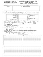
A typical DAQ system has three basic types of hardware—a terminal block,
a cable, and a DAQ device, as shown in Figure 1-1.
2
4
3
NATIONAL
INSTRUMENTS
NATIONAL
INSTRUMENTS
5
1
1
2
3
Signal
Terminal Block
Cable
4
5
DAQ Device
Computer
Figure 1-1. Typical DAQ System
After you have converted a physical phenomenon into a measurable signal
with or without signal conditioning, you need to acquire that signal. To
acquire a signal, you need a terminal block, a cable, a DAQ device, and a
computer. This hardware combination can transform a standard computer
into a measurement and automation system.
LabVIEW Core 1 Course Manual
1-2
ni.com
Lesson 1
Setting Up Hardware
Using a Terminal Block and Cable
Na
ti o
No na
t fo l I n
r D str
i st um
ri b e n
uti ts
on
A terminal block provides a place to connect signals. It consists of screw or
spring terminals for connecting signals and a connector for attaching a cable
to connect the terminal block to a DAQ device. Terminal blocks have 100,
68, or 50 terminals. The type of terminal block you should choose depends
on two factors—the device and the number of signals you are measuring.
A terminal block with 68 terminals offers more ground terminals to connect
a signal to than a terminal block with 50 terminals. Having more ground
terminals prevents the need to overlap wires to reach a ground terminal,
which can cause interference between the signals.
Terminal blocks can be shielded or non-shielded. Shielded terminal blocks
offer better protection against noise. Some terminal blocks contain extra
features, such as cold-junction compensation, that are necessary to properly
measure a thermocouple.
A cable transports the signal from the terminal block to the DAQ device.
Cables come in 100-, 68-, and 50-pin configurations. Choose a
configuration depending on the terminal block and the DAQ device you
are using. Cables, like terminal blocks, are shielded or non-shielded.
Refer to the DAQ section of the National Instruments catalog or to ni.com/
products for more information about specific types of terminal blocks and
cables.
© National Instruments Corporation
1-3
LabVIEW Core 1 Course Manual
Lesson 1
Setting Up Hardware
DAQ Signal Accessory
Na
ti o
No na
t fo l I n
r D str
i st um
ri b e n
uti ts
on
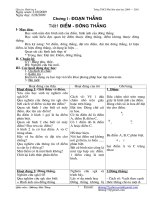
Figure 1-2 shows the DAQ Signal Accessory, one of the terminal blocks you
can use for this course.
Power
A
Quadrature A
Encoder B
B
Relay DIO 5
200mA Max
50-pin MIO Device (Diff Mode)
Lab/1200 Series (NRSE Mode)
68-pin Device (Diff Mode)
A
B
24 Pulses/rev
Digital Trigger
Digital Port 0
3
2
1
0
Frequency Frequency
Range
Adjust
13kHz-1MHz
1kHz-100kHz
Lo
Hi
100Hz-10kHz
Analog Analog Function
Out
In
Generator
Counters
Temp Sensor
Noise
Off
On
Temp Sensor
Mic Ch 6
DAQ
V*100 = °C
Signal Accessory
Ch 0
1
1
2
Ch 0
Figure 1-2. DAQ Signal Accessory
The DAQ Signal Accessory is a customized terminal block designed for
learning purposes. It has three different cable connectors to accommodate
many different DAQ devices and spring terminals to connect signals. You
can access three analog input channels, one of which is connected to the
temperature sensor, and two analog output channels.
The DAQ Signal Accessory includes a function generator with a switch to
select the frequency range of the signal, and a frequency knob. The function
generator can produce a sine wave or a square wave. A connection to ground
is located between the sine wave and square wave terminal.
LabVIEW Core 1 Course Manual
1-4
ni.com
Lesson 1
Setting Up Hardware
Na
ti o
No na
t fo l I n
r D str
i st um
ri b e n
uti ts
on
A digital trigger button produces a TTL pulse for triggering analog input or
output. When you press the trigger button, the signal goes from +5 V to 0 V
and returns to +5 V when you release the button. Four LEDs connect to the
first four digital lines on the DAQ device. The LEDs use reverse logic, so
when the digital line is high, the LED is off and vice versa.
The DAQ Signal Accessory has a quadrature encoder that produces
two pulse trains when you turn the encoder knob. Terminals are provided for
the input and output signals of two counters on the DAQ device. The DAQ
Signal Accessory also has a relay, a thermocouple input, and a microphone
jack.
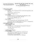
BNC-2120
Figure 1-3 shows the BNC-2120, which has similar features as the DAQ
Signal Accessory and can also be used to complete the exercises in this
course.
© National Instruments Corporation
1-5
LabVIEW Core 1 Course Manual
Lesson 1
Setting Up Hardware
1
NATIONAL
INSTRUMENTS
ANALOG INPUTS
Floating
Source (FS)
+
_
Ground Ref.
Source (GS)
+
_
AI 3
1
RES
!
PWR
BNC-2120
24
Na
ti o
No na
t fo l I n
r D str
i st um
ri b e n
uti ts
on
BNC
TIMING I/O
2
2
3
PFI 0 / P1.0
23
4
3
4
1. RES+
2. AI GND
3. AI SENSE
4. RES-
Temp.
Ref.
BNC
Quadrature
Encoder
Thermo
couple
BNC
5
96 Pulses/Rev
22
6
PULSES
UP /DN
AI 0
FS
GS
21
AI 1
FS
PFI 1 / P1.1
GS
PFI 2 / P1.2
PFI 3 / P1.3
PFI 4 / P1.4
PFI 5 / P1.5
AI 3
AI 2
PFI 6 / P1.6
7
FS
GS
FS
GS
PFI 7 / P1.7
PFI 8 / P2.0
8
20
PFI 9 / P2.1
PFI 12 / P2.4
AI 4
FS
GS
AI 5
FS
PFI 13 / P2.5
GS
PFI 14 / P2.6
+5 V
D GND
AI 6
FS
GS
USER-DEFINED
SIGNALS*
AI 7
FS
GS
19
ANALOG OUTPUTS
USER 1
9
18
USER 2
AO
AO 0
AO 1
*For BNC connections, wire
anyTiming I/O or Digital I/O
screw terminals here.
FUNCTION GENERATOR
Frequency Selection
10
DIGITAL I/O
0.1-10 kHz
1-100 kHz
17
P0.7
13-1000 kHz
P0.6
11
P0.5
P0.4
12
Sine/Triangle
P0.3
TTL Square Wave
16
P0.2
13
P0.1
14
15
1
2
3
4
5
6
7
8
9
10
11
12
P0.0
D GND
LO
HI
Amplitude Adjust
LO
HI
Frequency Adjust
RES/BNC Switch (AI 3)
Resistor Measurement Screw Terminals
Thermocouple Input Connector
Temperature Reference
BNC/Temp. Ref. Switch (AI 0)
BNC/Thermocouple Switch (AI 1)
Analog Input BNC Connectors
FS/GS Switches
Analog Output BNC Connector
Frequency Range Selection Switch
Sine/Triangle BNC Connector
TTL Square Wave BNC Connector
13
14
15
16
17
18
19
20
21
22
23
24
Sine/Triangle Waveform Switch
Frequency Adjust Knob
Amplitude Adjust Knob
Digital I/O Screw Terminals
Digital I/O LEDs
User-Defined Screw Terminals
User-Defined BNC Connectors
Timing I/O Screw Terminals
Quadrature Encoder Screw Terminals
Quadrature Encoder Knob
Timing I/O BNC Connector
Power Indicator LED
Figure 1-3. BNC-2120
LabVIEW Core 1 Course Manual
1-6
ni.com
Lesson 1
Setting Up Hardware
Using DAQ Devices
Na
ti o
No na
t fo l I n
r D str
i st um
ri b e n
uti ts
on
Most DAQ devices have four standard elements—analog input, analog
output, digital I/O, and counters.
You can transfer the signal you measure with the DAQ device to the
computer through a variety of different bus structures. For example, you can
use a DAQ device that plugs into the PCI or PCI Express bus of a computer,
a DAQ device connected to the PCMCIA socket of a laptop, or a DAQ
device connected to the USB port of a computer. You also can use
PXI/CompactPCI to create a portable, versatile, and rugged measurement
system.
If you do not have a DAQ device, you can simulate one in Measurement &
Automation Explorer (MAX) to complete your software testing. You learn
to simulate a device in the Simulating a DAQ Device section of this lesson.
Refer to the DAQ section of the NI catalog or to ni.com/products for
more information about specific types of DAQ devices.
Analog Input
Analog input is the process of measuring an analog signal and transferring
the measurement to a computer for analysis, display or storage. An analog
signal is a signal that varies continuously. Analog input is most commonly
used to measure voltage or current. You can use many types of devices to
perform analog input, such as multifunction DAQ (MIO) devices,
high-speed digitizers, digital multimeters (DMMs) and Dynamic Signal
Acquisition (DSA) devices.
Acquiring an analog signal with a computer requires a process known as
analog-to-digital conversion, which takes an electrical signal and translates
it into digital data so that a computer can process it. Analog-to-digital
converters (ADCs) are circuit components that convert a voltage level into
a series of ones and zeroes.
ADCs sample the analog signal on each rising or falling edge of a sample
clock. In each cycle, the ADC takes a snapshot of the analog signal, so that
the signal can be measured and converted into a digital value. A sample
clock controls the rate at which samples of the input signal are taken.
Because the incoming, or unknown signal is a real world signal with infinite
precision, the ADC approximates the signal with fixed precision. After the
ADC obtains this approximation, the approximation can be converted to a
series of digital values. Some conversion methods do not require this step,
because the conversion generates a digital value directly as the ADC reaches
the approximation.
© National Instruments Corporation
1-7
LabVIEW Core 1 Course Manual
Lesson 1
Setting Up Hardware
Analog Output
Na
ti o
No na
t fo l I n
r D str
i st um
ri b e n
uti ts
on
Analog output is the process of generating electrical signals from your
computer. Analog output is generated by performing digital-to-analog
(D/A) conversions. The available analog output types for a task are voltage
and current. To perform a voltage or current task, a compatible device must
be installed that can generate that form of signal.
Digital-to-analog conversion is the opposite of analog-to-digital conversion.
In digital-to-analog conversion, the computer generates the data. The data
might have been acquired earlier using analog input or may have been
generated by software on the computer. A digital-to-analog converter (DAC)
accepts this data and uses it to vary the voltage on an output pin over time.
The DAC generates an analog signal that the DAC can send to other devices
or circuits.
A DAC has an update clock that tells the DAC when to generate a new value.
The function of the update clock is similar to the function of the sample
clock for an ADC. At each cycle the clock, the DAC converts a digital value
to an analog voltage and creates an output as a voltage on a pin. When used
with a high speed clock, the DAC can create a signal that appears to vary
constantly and smoothly.
Digital I/O
Digital signals are electrical signals that transfer digital data over a wire.
These signals typically have only two states—on and off, also known as high
and low, or 1 and 0. When sending a digital signal across a wire, the sender
applies a voltage to the wire and the receiver uses the voltage level to
determine the value being sent. The voltage ranges for each digital value
depend on the voltage level standard being used. Digital signals have many
uses; the simplest application of a digital signal is controlling or measuring
digital or finite state devices such as switches and LEDs. Digital signals also
can transfer data; you can use them to program devices or communicate
between devices. In addition, you can use digital signals as clocks or triggers
to control or synchronize other measurements.
You can use the digital lines in a DAQ device to acquire a digital value. This
acquisition is based on software timing. On some devices, you can configure
the lines individually to either measure or generate digital samples. Each
line corresponds to a channel in the task.
You can use the digital port(s) in a DAQ device to acquire a digital value
from a collection of digital lines. This acquisition is based on software
timing. You can configure the ports individually to either measure or
generate digital samples. Each port corresponds to a channel in the task.
LabVIEW Core 1 Course Manual
1-8
ni.com
Lesson 1
Setting Up Hardware
Counters
Na
ti o
No na
t fo l I n
r D str
i st um
ri b e n
uti ts
on
A counter is a digital timing device. You typically use counters for event
counting, frequency measurement, period measurement, position
measurement, and pulse generation.
When you configure a counter for simple event counting, the counter
increments when an active edge is received on the source. In order for the
counter to increment on an active edge, the counter must be armed or started.
A counter has a fixed number it can count to as determined by the resolution
of the counter. For example, a 24-bit counter can count to:
2(Counter Resolution) – 1 = 224 – 1 = 16,777,215
When a 24-bit counter reaches the value of 16,777,215, it has reached the
terminal count. The next active edge forces the counter to roll over and start
at 0.
B. Using DAQ Software
National Instruments data acquisition devices have a driver engine that
communicates between the device and the application software. There are
two different driver engines to choose from: NI-DAQmx and Traditional
NI-DAQ. You can use LabVIEW to communicate with these driver engines.
In addition, you can use MAX to configure your data acquisition devices.
In this section, you learn about the driver engines and about using MAX to
configure your data acquisition device.
Using NI-DAQ
NI-DAQ 7.x contains two NI-DAQ drivers—Traditional NI-DAQ (Legacy)
and NI-DAQmx—each with its own application programming interface
(API), hardware configuration, and software configuration. NI-DAQ 8.0 and
later come with only NI-DAQmx, the replacement for Traditional NI-DAQ
(Legacy).
•
Traditional NI-DAQ (Legacy) is an upgrade to NI-DAQ 6.9.x, the earlier
version of NI-DAQ. Traditional NI-DAQ (Legacy) has the same VIs and
functions and works the same way as NI-DAQ 6.9.x. You can use
Traditional NI-DAQ (Legacy) on the same computer as NI-DAQmx,
which you cannot do with NI-DAQ 6.9.x. However, you cannot use
Traditional NI-DAQ (Legacy) on Windows Vista.
•
NI-DAQmx is the latest NI-DAQ driver with new VIs, functions, and
development tools for controlling measurement devices. The advantages
of NI-DAQmx over previous versions of NI-DAQ include the DAQ
Assistant for configuring channels and measurement tasks for a device;
increased performance, including faster single-point analog I/O and
© National Instruments Corporation
1-9
LabVIEW Core 1 Course Manual
Lesson 1
Setting Up Hardware
multithreading; and a simpler API for creating DAQ applications using
fewer functions and VIs than earlier versions of NI-DAQ.
Na
ti o
No na
t fo l I n
r D str
i st um
ri b e n
uti ts
on
Note (Windows) LabVIEW supports NI-DAQmx and the DAQ Assistant.
(Mac OS) LabVIEW supports NI-DAQmx Base but not the DAQ Assistant.
(Linux) LabVIEW supports NI-DAQmx but not the DAQ Assistant.
Traditional NI-DAQ (Legacy) and NI-DAQmx support different sets of
devices. Refer to Data Acquisition (DAQ) Hardware on the National
Instruments Web site for the list of supported devices.
DAQ Hardware Configuration
Before using a data acquisition device, you must confirm that the software
can communicate with the device by configuring the devices. The devices
are already configured for the computers in this class.
Windows
The Windows Configuration Manager keeps track of all the hardware
installed in the computer, including National Instruments DAQ devices. If
you have a Plug & Play (PnP) device, such as an E Series MIO device, the
Windows Configuration Manager automatically detects and configures the
device. If you have a non-PnP device, or legacy device, you must configure
the device manually using the Add New Hardware option in the Windows
Control Panel.
You can verify the Windows Configuration by accessing the Device
Manager. You can see Data Acquisition Devices, which lists all
DAQ devices installed in the computer. Double-click a DAQ device to
display a dialog box with tabbed pages. The General tab displays overall
information regarding the device. The Driver tab specifies the driver
version and location for the DAQ device. The Details tab contains additional
information about hardware configuration. The Resources tab specifies the
system resources to the device such as interrupt levels, DMA, and base
address for software-configurable devices.
LabVIEW Core 1 Course Manual
1-10
ni.com
Lesson 1
Setting Up Hardware
Measurement & Automation Explorer
Na
ti o
No na
t fo l I n
r D str
i st um
ri b e n
uti ts
on
MAX establishes all device and channel configuration parameters. After
installing a DAQ device in the computer, you must run this configuration
utility. MAX reads the information the Device Manager records in the
Windows Registry and assigns a logical device number to each DAQ device.
Use the device number to refer to the device in LabVIEW. Access MAX by
double-clicking the icon on the desktop or selecting Tools»Measurement
& Automation Explorer in LabVIEW. The following window is the
primary MAX window. MAX is also the means for SCXI and SCC
configuration.
1: AT-MIO-64E-3
Figure 1-4. The Primary MAX Window
The device parameters that you can set using the configuration utility
depend on the device. MAX saves the logical device number and the
configuration parameters in the Windows Registry.
The plug and play capability of Windows automatically detects and
configures switchless DAQ devices, such as the NI PCI-6024E, when you
install a device in the computer.
Scales
You can configure custom scales for your measurements. This is very useful
when working with sensors. It allows you to bring a scaled value into your
application without having to work directly with the raw values. For
example, in this course you use a temperature sensor that represents
temperature with a voltage. The conversion equation for the temperature is:
Voltage x 100 = Celsius. After a scale is set, you can use it in your
application program, providing the temperature value, rather than the
voltage.
© National Instruments Corporation
1-11
LabVIEW Core 1 Course Manual
Lesson 1
Setting Up Hardware
Simulating a DAQ Device
Na
ti o
No na
t fo l I n
r D str
i st um
ri b e n
uti ts
on
You can create NI-DAQmx simulated devices in NI-DAQmx 7.4 or later.
Using NI-DAQmx simulated devices, you can try NI products in your
application without the hardware. When you later acquire the hardware, you
can import the NI-DAQmx simulated device configuration to the physical
device using the MAX Portable Configuration Wizard. With NI-DAQmx
simulated devices, you also can export a physical device configuration onto
a system that does not have the physical device installed. Then, using the
NI-DAQmx simulated device, you can work on your applications on a
portable system and upon returning to the original system, you can easily
import your application work.
C. Instrument Control
When you use a PC to automate a test system, you are not limited to the type
of instrument you can control. You can mix and match instruments from
various categories. The most common categories of instrument interfaces
are GPIB, serial, and modular instruments. Additional types of instruments
include image acquisition, motion control, USB, Ethernet, parallel port,
NI-CAN, and other devices.
When you use PCs to control instruments, you need to understand properties
of the instrument, such as the communication protocols to use. Refer to the
instrument documentation for information about the properties of an
instrument.
D. GPIB
The ANSI/IEEE Standard 488.1-1987, also known as General Purpose
Interface Bus (GPIB), describes a standard interface for communication
between instruments and controllers from various vendors. GPIB, or
General Purpose Interface Bus, instruments offer test and manufacturing
engineers the widest selection of vendors and instruments for
general-purpose to specialized vertical market test applications. GPIB
instruments are often used as stand-alone benchtop instruments where
measurements are taken by hand. You can automate these measurements
by using a PC to control the GPIB instruments.
IEEE 488.1 contains information about electrical, mechanical, and
functional specifications. The ANSI/IEEE Standard 488.2-1992 extends
IEEE 488.1 by defining a bus communication protocol, a common set of
data codes and formats, and a generic set of common device commands.
LabVIEW Core 1 Course Manual
1-12
ni.com
Lesson 1
Setting Up Hardware
Na
ti o
No na
t fo l I n
r D str
i st um
ri b e n
uti ts
on
GPIB is a digital, 8-bit parallel communication interface with data transfer
rates of 1 Mbyte/s and higher, using a three-wire handshake. The bus
supports one system controller, usually a computer, and up to 14 additional
instruments.
The GPIB protocol categorizes devices as controllers, talkers, or listeners to
determine which device has active control of the bus. Each device has a
unique GPIB primary address between 0 and 30. The Controller defines the
communication links, responds to devices that request service, sends GPIB
commands, and passes/receives control of the bus. Controllers instruct
Talkers to talk and to place data on the GPIB. You can address only
one device at a time to talk. The Controller addresses the Listener to listen
and to read data from the GPIB. You can address several devices to listen.
Data Transfer Termination
Termination informs listeners that all data has been transferred. You can
terminate a GPIB data transfer in the following three ways:
•
The GPIB includes an End Or Identify (EOI) hardware line that can be
asserted with the last data byte. This is the preferred method.
•
Place a specific end-of-string (EOS) character at the end of the data
string itself. Some instruments use this method instead of or in addition
to the EOI line assertion.
•
The listener counts the bytes transferred by handshaking and stops
reading when the listener reaches a byte count limit. This method is
often a default termination method because the transfer stops on the
logical OR of EOI, EOS (if used) in conjunction with the byte count.
As a precaution, the byte count on the listener is often set higher than the
expected byte count so as not to miss any samples.
Data Transfer Rate
To achieve the high data transfer rate that the GPIB was designed for,
you must limit the number of devices on the bus and the physical distance
between devices.
You can obtain faster data rates with HS488 devices and controllers.
HS488 is an extension to GPIB that most NI controllers support.
Note Refer to the National Instruments GPIB support Web site at ni.com/support/
gpibsupp.htm for more information about GPIB.
© National Instruments Corporation
1-13
LabVIEW Core 1 Course Manual