Hướng dẫn hệ thống điện đầu kéo Freightliner M2 EPA 2010 Electrical Guide
Bạn đang xem bản rút gọn của tài liệu. Xem và tải ngay bản đầy đủ của tài liệu tại đây (4.38 MB, 43 trang )
EPA 2010 M2 Electrical
Body Builder Reference Guide
Electrical System Overview
2010 M2 Electrical Body Builder Reference Title Page Rev New
EPA 2010 Models
Electrical System Overview
2010 M2 Electrical Body Builder Reference Page # 1 Rev New
EPA 2010 Models
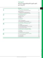
Index
Page 1 Index
Page 2 Electrical Component Overview
Page 3 Electrical Harness Overview
Page 4 Electrical Power flow Overview
Page 5
Page 6
Page 7
Page 8
Page 9 Bulk Head Module (BHM)
Page 10 Bulk Head Module (BHM) Pin Detail
Page 11 Chassis Module (CHM)
Page 12
PNDB Power Net Distribution Box
Positive Disconnect Switch
Main Power Distribution Module (PDM)
PDM / VBAT Fuse Coverage
Chassis Module (CHM) Pin Detail
Page 13 Multiplexing System Backbone
Page 14 System Tap Points
Page 15 J1708 Gateway
Page 16 Low Current Smart Switches
Page 17 High Current Switches (Battery Hot)
Page 18 High Current Switch (BH) Schematics
Page 19 High Current Switches (Ignition Interlocked)
Page 20 High Current Switch (Ignition Interlocked) Schematics
Page 21 High Current Switch Label Options
Page 22 Body Builder Lighting Interface
Page 23 Body Builder PDM
Page 27 Trailer Electrical Schematics (Combination)
PTO Installation
Page 36 PTO PTO Controls
Page 37 PTO Air Schematics
Page 38 PTO Electrical Schematics
Page 39 Hybrid PTO Options
Page 40 Remote Start Stop Schematics
Page 41 M2 VDR Prep Information (NFPA)
Page 42 M2 VDR to M2 Connections
Page 24 Body Lighting Interface Schematics
Page 25 Trailer PDM
Page 26 Trailer Electrical Schematics (Seperate)
Page 28 Wired Rite Prep
Page 29 Wired Rite Schematic
Page 30 Wired Rite Trailer and Floor connections
Page 31 Tail Lights
Page 32 Tail Light Schematics
Page 33 Transmission Interface
Page 34 Engine Interface
Page 35
Bulk Head Module
(BHM)
(Module 32A)
Power Distribution
(Module 285 PDM)
Chassis Module
(CHM Under Cab)
(Module 335, 32K)
Accessory Air
Valve Assembly (AAVA)
(Multiple Modules )
Body lighting
Interfaces
(Module 353, 296)
Dash Switches
(Module 329)
Tail Light
Configurations
(Module 294)
Trailer Interfaces
(Module 296, 297)
(Module )
Engine Interface
(Black Plug)
(Plugs may also
be frame located)
148, 163, 87L
Transmission
(Grey Plug)
(Plugs may also
frame located
Interfaces.
be
(Module , 34C)
Electrical Component Overview
2010 M2 Electrical Body Builder Reference Page # 2 Rev: New
EPA 2010 Models
PNDB Power Net Distribution
Box (Module 33P/281/293)
Electrical Harness Overview
FORWARD CHASSIS HARNESS Module
1) Connections to Bulkhead module and Underhood PDM
2) Connections to headlamps
3) Connections to side marker/turn lamps
4) Connections to Chassis Module
288
AFT CHASSIS HARNESS Module
1) Connections to Chassis Module
2) Connections to tail lamps
28A
MAIN CAB HARNESS Module
1) Connections to bulkhead connector
2) Connections to diagnostic connector (behind ignition switch)
3) Connections to CPC
4) Pass-thru connector to engine compartment
5) Gauge Cluster
6) HVAC unit and controler
7) Steering wheel horn and windshield wiper
320
OVERHEAD CAB HARNESS Module 287
1) Inline connection to Main cab Harness
(at bottom of A pillar)
2) Connections to Marker Lamps
3) Connections to Dome Lamp
FRONTWALL HARNESS Module 321
1) Connections to Bulkhead Module and Underhood PDM
2) Connection to Starter Mag Switch
3) Connection to Wiper Motor
4) Connection to the low coolant level sensor and horn (under surge tank)
5) Connection under cab to Washer pump and level switch
6) Pass-thru connector to Main Cab Harness and Powertrain Harness
POWERTRAIN HARNESS Module 286, 283
1) Connections to the Bulkhead
Module and Underhood PDM
ABS/AMU HARNESS Module 332
1) Connections to Forward chassis
harness and frame ground studs near
Chassis module
2) Connections to AMU (Mod 877 without ABS)
3) Connections to Wabco ABS ECU
4) Connections to rear combo valves
2010 M2 Electrical Body Builder Reference Page # 3 Rev: New
EPA 2010 Models
Electrical Power Flow Overview
2010 M2 Electrical Body Builder Reference Page # 4 Rev: New
EPA 2010 Models
Battery
Main PNDB
TCM
Trailer PDM
Tail Lights
BB PNDB
Body Lighting Conn
Transmission Connector
BB PDM
Trailer Connector
Engine Connector
Main PDM
BHM
Powertrain
PDM
ECM
ICU
CHM
C2-F Trailer Marker Relay
C2-H Trailer Turn Left Relay
C2-E Trailer Turn Right Relay
C2-A Trailer Power Relay
C2-D Trailer Stop Lamp Relay
Chassis Module Outputs
Bulkhead Module Outputs
B5.E - SPARE (Utility Light/Spotlight)
B4.M - SPARE (Utility Light/Spotlight)
B3.E - Horn
B5.F - Cigar Lighter Output
B5.H - Panel Lamps
B7.A1 - Panel Lamps (Smart Switch)
B5.G - SPARE (Ignition)
B6.A9 - Accessory (HVAC)
B6.A10 - Accessory (Radio)
B4.F - SPARE (Left Heated Mirror)
B4.E - SPARE (Right Heated Mirror)
B6.A8 - Ignition (VCU)
B2.K - Ignition (Engine)
B1.P - Ignition (ABS)
B5.A - Battery (Dome Lamps)
B7.A12 - Battery (Smart Switch)
B5.D - Instrument Cluster
B5.B - Dome Lamps Switched
B1.L - Left High Beam
B2.L - Ignition (Trans)
B1.F - Fuel Water Sensor Power
B3.F - Wiper High
B5.C - Clearance Lamps
B1.K - Tail/License Plate
B1.R - Left Low Beam
B3.H - Wiper Low
B3.G - Washer Pump
B2.M - AC Clutch
B4.B - Starter Relay (Crank)
/Trailer Relay
C3-A Optional Fuel Water Separator Heater
C4-C Left Park Lamp
C4-L Right Park Lamp
C4-D Left Marker Lamp
C4-M Right Marker Lamp
C3-N Turn Left Front/Side
C1-G Turn Left Rear
C3-R Turn Right Front/Side
C1-P Turn Right Rear
C1-A Left Backup Lamp
C1-J Right Backup Lamp
C1-H Backup Alarm
C3-L Right Low Beam
C4-K Right High Beam
C1-N Left Stop Lamp
C1-L Right Stop Lamp
C3-K Right DRL
C4-F Left DRL
C3-C Optional Fog/Road Lamps
C3-D Optional Fog/Road Lamps
C5-H AMU Solenoid #0
C5-J AMU Solenoid #1
C5-L AMU Solenoid #2
C5-M AMU Solenoid #3
ECM
TCM
BHM
CHM
ICU
BB
PNDB
Main
PNDB
Main
PDM
Powertrain
PDM
BB
PDM
Trailer
PDM
Battery
(296) Trailer
Connector
(353) Body
Lighting Conn
Engine
Connector
Transmission
Connector
(294) Tail
Lights
J1939
Multiplexed
Network
PNDB Power Net Distribution Box
2010 M2 Electrical Body Builder Reference Page # 5 Rev: New
EPA 2010 Models
INSTALLATION WITHOUT
DISCONNECT SWITCH
INSTALLATION WITH
DISCONNECT SWITCH
Primary
Solenoid
for Cut off
Switch
Battery
Input
Primary Solenoid
Cut Off Switch
Connection
ATC Fuse
Output
ATC Fuses
MIDI Fuse
Output
Fuse Cover
and label
Power Net Distribution Box (PNDB)
The PNDB is a new power delivery system for the
M2 designed to deliver more consistent and better
protected power from the battery to the other components
on the truck.
The PNDB also has protected keep alive circuits that
maintain power even with the cutoff switch is in the off position.
The primary reason for this change is to provide power to the
2010 DEF purge system which drains urea from the delivery
system and prevents the system from freezing during cold
conditions.
The PNDB located at the front wall is equipped with three
MIDI fuses which supply power to the Main Power
Distribution Module. These fuse connections have been
relocated from the battery in 2010 to prevent corrosion
and improve the trucks reliability in severe conditions.
A secondary PNDB is available as an option for the body builder and
will be located with the trailer and bodybuilder PDM located in the cab
behind the drivers seat on day cabs or under the rear bench seat for
crew cab units.
ATC -A
ATC -B
ATC -C
ATC -D
ATC Fuse output
keeps power on after
disconnect
Mating connector
23-13153-410
1
A
2
2
3
1
A
B
C
D
B
3
C
A
D
B
E
C
F
4
D
Battery Input
300 AMPS Max
AFTER TREATMENT ECU
EMERGENCY POWER
RADIO AND CLOCK
ALTERNATOR REMOTE SENSE
GROUND
X2 KEEP ALIVE
CIRCUIT
X1 SOLENOID
CONTROL
SIGNAL OFF
LED INDICATOR
SIGNAL ON
SIGNAL RETURN
GROUND
1
2
3
4
A
B
C
D
E
F
CONNECTOR
PIN
DESCRIPTION
Fuse Description Function Rating Max. Fuse Allowed
ATC-A Keep Alive Power After Treatment ECU 30 AMPS 30 AMPS
ATC-B Keep Alive Power Emergency Power 20 AMPS 30 AMPS
ATC-C Keep Alive Power Radio and Clock 5 AMPS 30 AMPS
ATC-D Keep Alive Power Alternator Remote Sense 5 AMPS 30 AMPS
MIDI-1 (Fuse 1) High AMP Fuse Powertrain PDM 175 AMPS 200 AMPS
MIDI-2 (Fuse 2) High AMP Fuse
PDM #2
125 AMPS 200 AMPS
MIDI-3 (Fuse 3) High AMP Fuse PDM #1 125 AMPS 200 AMPS
Solenoid Control
Positive Cutoff Switch
2010 M2 Electrical Body Builder Reference Page # 6 Rev: New
EPA 2010 Models
Battery Box Disconnect Switch Mounting
with box mounted air tanks
(brackets will vary depending on application)
293-061
In Cab Mounted Disconnect
Switch Mounting
293-058
Battery Box Mounting
without box mounted air tanks
293-001, 293-061
Disconnect Switch
Positive Disconnect Switch
The disconnect switch system for 2010 has been reconfigured
to provide better application coverage and offer two levels
of power disconnect based on the options ordered with the truck.
In cab disconnect switches will be offered in a locking or non locking
configuration.
Exterior battery mounted switches will be offered in the locking
configuration only.
Cutoff switches are equipped with red LED lights, which are
when power is on.
Trucks equipped with the body builder auxiliary power system
will have an additional LED light on the switch.
Note: Both PNDB units will be deactivated when the switch is in
the off position.
illuminated
Axillary Body Builder
Cutoff Switch
Standard
Cutoff Switch
Standard Power LED
Lockout Tab
Auxiliary Power
and Main Power
LED
Main Cab PNDB
Connector Plug
#23-13153-307
Body Builder PNDB
Connector Plug
#23-13662-401
1
3
2
1
4
2
3
293-057
293-061
293-060
293-058
NEGATIVE LOAD DISCONNECT W/CAB MTD DISCONNECT SWITCH
NEGATIVE LOAD DISCONNECT W/BATTERY BOX DISCONNECT SWITCH
POSITIVE LOAD DISCONNECT W/BATTERY BOX CTRL SWITCH W/LOCKING PROVISION
POSITIVE LOAD DISCONNECT W/CAB MTD CTRL SW W/LOCKING PROV MTD OB DR DEAT
POSITIVE LOAD DISCONNECT W/CAB MTD CONTROL SWITCH MTD OB DR SEAT
293-063
X2, Aux PNDB
X1, Main PNDB
The main Power Distribution Module (PDM) distributes
battery power to the various control modules on the
vehicle.
The PDM contains mini fuses that
the power feed circuits to these modules.
For most trucks there will be spare fuse slots available
customers to add additional wiring to the truck after
purchased.
There are four plugs attaching to the module that supply
output connections.
Common spare fuse sockets are listed below but may
vary based on the options that have been requested.
Common Spare Fuse locations
F6, F10, F11, F14, F21, F23, F25, F26
protect
for
it is
A
B
B
A
A
C
B
G
H
E
G
D
C
B
A
D
B
F
C
D
H
H
G
G
D
C
H
E
E
F
Single Wire Output
found on
Plug in Pin G
Green
PDM Plugs
contain output
wires
PDM #1
(MIDI-3)
PDM # 2
(MIDI-2)
Engine Harness
Plug (Green)
Forward Chassis
Harness Plug (Blue)
Forward
Chassis
Harness
Plug
(Grey)
Front
Wall
Harness
Plug
(Black)
Main Power Distribution Module (PDM)
Power Distribution Module Fuse Specications*
Output
MEGA
Fuse
Connection
Fuse
Location
Primary Function
Fuse
Rating
Secondary Function
Fuse
Rating
Green A
1
F1
Spare
{
Green B
Green H
1
F2 Blower Motor 30A {
{
{
{
{
2
F3
Spare
Spare
Spare
30A
Green G
2
F4
30A
30A
Black D
1
2
F5 Ignition Switch 5A { {
Black C
1
1
F6
Hydromax Relay
Gray F
1
1
F7 Bulkhead Module 30A { {
Green C
2
2
2
2
2
2
2
2
F8 ICU3-M2 10A {
{
{
Green D
2
1
1
1
1
1
1
F9
†
30A
Blue G
Green F
2
F10
Spare
Spare
{
{
{
{
{
{
{
{
Blue H
F11 Spare { { {
Black H
F12 Radio/Diagnostic 20A { {
Grey E
F13 Chassis Module 30A { {
Black B
F14 Spare { { {
Black A
F15 Bulkhead Module 30A { {
Blue A
F16
ABS ECU (pneumatic)
15A
ABS ECU (hydraulic)
25A
25A
Blue C
F17 Chassis Module 30A { {
Blue B
F18 Bulkhead Module 30A { {
Grey G
F19 Chassis Module 30A { {
Black E
F20 Bulkhead Module 30A { {
Black F
Grey H
Grey B
F21 Spare { { {
Black G
Blue E
Blue D
F22 Bulkhead Module 30A { {
F23
Spare
{
{
{
{
Grey D
F24
Hydraulic Pump and
Spare
Grey C
F25 Spare { { {
Multiple Wire output
Pin A & B on Grey
Plug and Pin D
on Blue Plug
Grey A
F26
Spare
{
{
{
2010 M2 Electrical Body Builder Reference Page # 7 Rev: New
Motor (hydraulic ABS)
VBAT 1 BHM
VBAT 2 BHM
VBAT 3 BHM
VBAT 4 BHM
VBAT 5 BHM
VBAT 1 CHM
VBAT 2 CHM
VBAT 3 CHM
F
VBAT
Fuse
Pin part number for harness connection
23-13213-120 TERM-FEMALE,(20-16) PAC12077411
23- -121 TERM- ,(14-12) PAC1212949313213 FEMALE
23-13213-122 TERM-FEMALE,(10) PAC12077413
EPA 2010 Models
Power Supply Fuses and Associated Outputs for the Bulkhead Module
BHM Power Input
BHM Power
Input Pin
Fuse Supplying BHM
Power Input
BHM Outputs Supplied
BHM
Power In
Power Out
Battery (dome lamps)
B5.A
Battery (smart switches)
B7.A12
Ignition (VCU)
B6.A8
Ignition (engine)
B2.K
Ignition (ABS)
B1.P
Ignition (trans)
B2.L
Fuel Water Sensor Power
B1.F
Dome Lamps Switched
B5.B
Left Low Beam
B1.R
A/C Clutch
B2.M
Smart Switch 1 Indicator
B7.B4
Smart Switch 2 Indicator
B7.B8
Smart Switch 3 Indicator
B7.A5
Smart Switch 4 Indicator
B7.A9
Smart Switch 5 Indicator
B7.B10
VBAT1
B3.D Fuse 22 (30A)
Battery (smart switch)
B7.A12
Accessory (HVAC)
B6.A9
Accessory (radio)
B6.A10
Wake Up (instrument cluster)
B5.D
Left High Beam
B1.L
Wiper High
B3.F
VBAT2
B4.G Fuse 20 (30A)
Horn
B3.E
Wiper Low
B3.H
Spare 8.0A HSD (ignition)
B5.G
Panel Lamps
B5.H
VBAT3
B1.N Fuse 18 (30A)
Panel Lamps (smart switch)
B7.A1
Clearance Lamps
B5.C
Tail Lamps/License Plate
Relay
B1.K*
Washer Pump
B3.G
VBAT4
B4.K Fuse 15 (30A)
12V Output (cigar lighter)
B5.F
Spare 8.5A (utility light/spotlight)
B5.E / B4.M
Left Heated Mirror
B4.F
VBAT5
B1.J Fuse 7 (30A)
Right Heated Mirror
B4.E
Power Supply Fuses and Associated Outputs for the Chassis Module
CHM Power
Input
CHM Power
Input Pin
Fuse Supplying CHM
Power Input
CHM Outputs Supplied
CHM
Power In
Power Out
Right Low Beam
C3.L
Turn Right Front/Side
C3.R
Turn Right Rear
C1.P
Right Stop Lamp
C1.L
Left Stop Lamp
C1.N
Right DRL
C3.K
Fog/Road Lamps
C3.C/C3.D
VBAT1
C4.P
Fuse 19 (30A)
Trailer Turn Right
C2.E
Left Park Lamp
C4.C
Right Park Lamp
C4.L
Left Marker Lamp
C4.D
Right Marker Lamp
C4.M
Trailer Marker Relay
C2.F
Right High Beam
C4.K
Left Backup Lamp
C1.A
Right Backup Lamp
C1.J
Backup Alarm
C1.H
Turn Left Front/Side
C3.N
Turn Left Rear
C1.G
Left DRL
C4.F
VBAT2
C3.J
Fuse 17 (30A)
Trailer Turn Left
C2.H
Fuel Water Separator Heater
C3.A
AMU Solenoid 0
C5.H
AMU Solenoid 1
C5.J
AMU Solenoid 2
C5.L
VBAT3
C4.J
Fuse 13 (30A)
AMU Solenoid 3
C5.M
Output Pin
Lamp/Trailer Tail
Output Pin
VBAT Fuse System
BHM and CHM output pins are powered by multiple VBAT fuses
through the main M2 PDM unit. If one of these fuses is tripped or
blown then all pins in the circuit will be affected. For this reason
seemingly unrelated issues can occur at the same time if a fuse
is overloaded and trips.
The lists below show which pins are controlled with the VBAT fuses.
PDM VBAT Fuse Coverage
2010 M2 Electrical Body Builder Reference Page # 8 Rev: New
EPA 2010 Models
Bulkhead Module BHM
Chassis Module CHM
Bulk Head Module (BHM)
The Bulkhead Module (BHM)
The BHM is the primary command module for the M2 electrical system.
The module controls the operation of the other component
the either directly or indirectly using messages sent over
The Bulkhead Module is mounted on the driver side of the front wall and connects
to the interior wiring through an opening in the front wall.
The BHM has four harness connections on the engine side of the front wall and
three harness connections to the cab interior.
The BHM Unit contains all system parameters and the unit controls power flow
and circuit protection to the various components of the M2 electrical system.
The BHM unit can also support up to 5 smart switches. The BHM is
programable and can be changed and updated by flashing the unit through
service link.
Power supply for the BHM is supplied using VBAT fuses, which reside in the
main PDM (see page 3)
The BHM is programmable and the feature screen in service link can be used to
or add parameters to the BHM
modules in
system the J1939 network.
directly
change
B4 Front
Wall Harness
B3 Front
Wall Harness
B1 Forward Chassis
Harness
B2 Engine
Harness
B6 Dash
Harness
B5 Dash
Harness
B7 Dash
Harness
B5.E - SPARE (Utility Light/Spotlight)
B4.M - SPARE (Utility Light/Spotlight)
B3.E - Horn
B5.F - Cigar Lighter Output
B5.H - Panel Lamps
B7.A1 - Panel Lamps (Smart Switch)
B5.G - SPARE (Ignition)
B6.A9 - Accessory (HVAC)
B6.A10 - Accessory (Radio)
B4.F - SPARE (Left Heated Mirror)
B4.E - SPARE (Right Heated Mirror)
B6.A8 - Ignition (VCU)
B2.K - Ignition (Engine)
B1.P - Ignition (ABS)
B5.A - Battery (Dome Lamps)
B7.A12 - Battery (Smart Switch)
B5.D - Wake Up (Instrument Cluster)
B5.B - Dome Lamps Switched
B1.L - Left High Beam
B2.L - Ignition (Trans)
B1.F - Fuel Water Sensor Power
B3.F - Wiper High
B5.C - Clearance Lamps
B1.K - Tail/License Plate/Trailer Relay
B1.R - Left Low Beam
B3.H - Wiper Low
B3.G - Washer Pump
B2.M - AC Clutch
B4.B - Starter Relay (Crank)
6.7A
6.7A
6.7A
6.7A
6.7A
6.7A
Combined
6.7A
6.7A
6.7A
6.7A
6.7A
Combined
6.7A
Combined
6.7A
Combined
12A
Combined
12A
12A
Combined
12A
20A
Combined
- Bulkhead Module outputs have defined amperage limits.
- If higher loads are required, bulkhead module outputs should be used as signal
power in conjunction with a relay.
Key Bulkhead Module Outputs
2010 M2 Electrical Body Builder Reference Page # 9 Rev: New
Pin part numbers for harness connection
FEMALE
23-13212-122 TERM-FEMALE,(10) PAC15326004
Inside Cab Connections:
PAC12129494 TERM-FEMALE,(12-14)
PAC12034046 TERM-FEMALE,(16-18)
Outside Cab Connections:
23-13212-120 TERM-FEMALE,(18-16) PAC153047191
23-13212-121 TERM- ,(14-12) PAC15304720
EPA 2010 Models
Bulk Head Module (BHM) Pin Detail
B4 Front
Wall Harness
B3 Front
Wall Harness
B1 Forward
Chassis Harness
B2 Engine
Harness
B6 Dash
Harness
A B C D
E F G H
A B C D E F
G H J K L M
A B C D
H G F E
A B C D E F
H J K L M N P
G
B1 B2 B3 B4 B5 B6 B7 B8 B9 B10 B11 B12
A1 A2 A3 A4 A5 A6 A7 A8 A9 A10 A1
1 A12
B1 B2 B3 B4 B5 B6 B7 B8 B9 B10 B11 B12
A1 A2 A3 A4 A5 A6 A7 A8 A9 A10 A1
1 A12
S R P N M L
H G F E D C B A
K J
B5 Dash
Harness
B7 Dash
Harness
Connector B1 Forward Chassis Harness Pinouts
Connector Pin Signal Name Signal Type
B1-A
|
|
B1-B Module Wake-Up Signal
Digital Input/
Output
B1-C Spare Digital Input 4 Digital Input
B1-D
|
|
B1-E Ground Power Ground
B1-F Fuel/Water Sensor Ignition Power Digital Output
B1-G Ground Signal Ground
B1-H J1587+ Datalink Datalink
B1-J Battery Power (VBAT5) Power
B1-K Tail Lamps/License Plate Lamp/Trailer Tail Relay Digital Output
B1-L Left High Beam Digital Output
B1-M Fuel/Water Separator (spare digital input 5) Digital Input
B1-N Battery Power (VBAT3) Power
B1-P ABS Ignition Power Digital Output
B1-R Left Low Beam Digital Output
B1-S J1587{ Datalink Datalink
Connector B2 Engine Harness Pinouts
Connector Pin Signal Name Signal Type
B2-A J1587+ Datalink Datalink
B2-B J1939+ Datalink Datalink
B2-C J1587+ Datalink Datalink
B2-D J1587{ Datalink Datalink
B2-E
|
|
B2-F
|
|
B2-G Backup Switch (spare digital input 3) Digital Input
B2-H J1587{ Datalink Datalink
B2-J J1939{ Datalink Datalink
B2-K Engine ECU Ignition Power Digital Output
B2-L Transmission ECU Ignition Power Digital Output
B2-M A/C Clutch Digital Output
B2-N
|
|
B2-P Alternator Charging Digital Input
Connector B3 Frontwall Harness Pinouts
Connector Pin Signal Name Signal Type
B3-A J1939{ Datalink Datalink
B3-B J1939+ Datalink Datalink
B3-C Wiper Parked Position Digital Input
B3-D Main Battery Power (VBAT1) Power
B3-E Horn Digital Output
B3-F Wiper Motor High Speed Digital Output
B3-G Washer Pump Digital Output
B3-H Wiper Motor Low Speed Digital Output
Connector B6 Dash Harness Pinouts
Connector Pin Signal Name Signal Type
B6-A3 Ignition Switch On Digital Input
B6-A4
|
|
B6-A5 Ignition Switch Start Digital Input
B6-A6 Passenger Door Open (spare digital input 10) Digital Input
B6-A7 Driver Door Open Digital Input
B6-A8 VCU Ignition Power Digital Output
B6-A9 HVAC Power Digital Output
B6-A10 Radio Power Digital Output
B6-A11 J1587{ Datalink Datalink
B6-A12 J1587+ Datalink Datalink
B6-B1 Horn Switch Digital Input
B6-B2 Top of Clutch Switch (spare digital input 7) Digital Input
B6-B3 Bottom of Clutch Switch (spare digital input 6) Digital Input
B6-B4
|
|
B6-B5 Panel Lamps Increase Digital Input
B6-B6 Panel Lamps Decrease Digital Input
B6-B7 A/C Clutch Request Digital Input
B6-B8 Hazard Switch Digital Input
B6-B9 Headlamp Switch PARK Position Digital Input
B6-B10 Headlamp Switch On Position Digital Input
B6-B11 Headlamp Switch On 2 Position Digital Input
B6-B12
|
|
Connector B7 Dash Harness Pinouts
Connector Pin Signal Name Signal Type
B7-A1 Panel Lamps (smart switch) Digital Output
B7-A2 Smart Switch 3 ID 1 Analog Input
B7-A3 Smart Switch 3 ID 2 Analog Input
B7-A4 Smart Switch 3 Input Analog Input
B7-A5 Smart Switch 3 Indicator Digital Output
B7-A6 Smart Switch 4 ID 1 Analog Input
B7-A7 Smart Switch 4 ID 2 Analog Input
B7-A8 Smart Switch 4 Input Analog Input
B7-A9 Smart Switch 4 Indicator Digital Output
B7-A10 Smart Switch 5 ID 1 Analog Input
B7-A11 Smart Switch 5 ID 2 Analog Input
B7-A12 Smart Switch Battery Power Digital Output
B7-B1 Smart Switch 1 ID 1 Analog Input
B7-B2 Smart Switch 1 ID 2 Analog Input
B7-B3 Smart Switch 1 Input Analog Input
B7-B4 Smart Switch 1 Indicator Digital Output
B7-B5 Smart Switch 2 ID 1 Analog Input
B7-B6 Smart Switch 2 ID 2 Analog Input
B7-B7 Smart Switch 2 Input Analog Input
B7-B8 Smart Switch 2 Indicator Digital Output
B7-B9 Ground Signal Ground
B7-B10 Smart Switch 5 Indicator Digital Output
B7-B11 Smart Switch 5 Input Analog Input
B7-B12
|
|
Connector B4 Frontwall Harness Pinouts
Connector Pin
Signal Name
Signal Type
B4-A Air Filter Restriction/Spare #9 Digital Input
B4-B Starter Relay Digital Output
B4-C Ground Ground
B4-D Spare Digital Input 2 Digital Input
B4-E Right Heated Mirror (spare digital output) Digital Output
B4-F Left Heated Mirror (spare digital output) Digital Output
B4-G Main Battery Power (VBAT2) Power
B4-H Module Wake-Up Signal Digital Input/Output
B4-J
|
|
B4-K Main Battery Power (VBAT4) Power
B4-L Washer Fluid Level (spare digital input 8) Digital Input
B4-M Utility Light/Spotlight (spare digital output) Digital Output
Connector B5 Dash Harness Pinouts
Connector Pin Signal Name Signal Type
B5-A Dome Lamps Battery Digital Output
B5-B Dome Lamps Switched Digital Output
B5-C Clearance Lamps (cab) Digital Output
B5-D Instrument Cluster Wake-Up Digital Output
B5-E Utility Light/Spotlight (spare digital output) Digital Output
B5-F Cigar Lighter Digital Output
B5-G Ignition Power, Other (spare digital output) Digital Output
B5-H Panel Lamps Digital Output
B6-A1
Ignition Switch Accessory Position
Digital Input
B6-A2
Module Wake-Up Signal
Digital Input
2010 M2 Electrical Body Builder Reference Page # 10 Rev: New
EPA 2010 Models
Chassis Module (CHM)
C3-A Optional Fuel Water Separator Heater
C4-C Left Park Lamp
C4-L Right Park Lamp
C4-D Left Marker Lamp
C4-M Right Marker Lamp
C2-F Trailer Marker Relay
C3-N Turn Left Front/Side
C1-G Turn Left Rear
C2-H TrailerTurn Left
C3-R Turn Right Front/Side
C1-P Turn Right Rear
C2-E TrailerTurn Right
C1-A Left Backup Lamp
C1-J Right Backup Lamp
C1-H Backup Alarm
C3-L Right Low Beam
C4-K Right High Beam
C1-N Left Stop Lamp
C1-L Right Stop Lamp
C3-K Right DRL
C4-F Left DRL
C3-C Optional Fog/Road Lamps
C3-D Optional Fog/Road Lamps
C5-H AMU Solenoid #0
C5-J AMU Solenoid #1
C5-L AMU Solenoid #2
C5-M AMU Solenoid #3
C2-A Trailer Power Relay
0.85A
0.85A
0.85A
0.85A
0.2A
10A
Combined
7.5A
Combined
7.5A
Combined
6.7A
Combined
20A
6.7A
Combined
6.7A
6.7A
6.7A
6.7A
6.7A
6.7A
Key Chassis Module Outputs
C2 Trailer
Module Harness
C1 Tail Light
Harness
C4 Forward
Chassis
Harness
C3 Forward
Chassis
Harness
C5 Air
UnitManagement
2010 M2 Electrical Body Builder Reference Page # 11 Rev: New
Pin part number for harness connection
23-13212-120 TERM-FEMALE,(18-16) PAC153047191
23-13212-121 TERM- ,(14-12) PAC15304720FEMALE
23-13212-121 TERM-FEMALE,(10) PAC15326004
EPA 2010 Models
Chassis Module (CHM)
The Chassis Module (CHM) and the Expansion Module (EXM)
both serve the same function in the M2 electrical system by acting
as dependants to the Bulkhead Module (BHM).
The CHM and XEM respond to commands from the BHM and
broadcast the status of the inputs and outputs that are sent to,
and delivered by the module.
The M2 system will always come equipped with chassis Module,
but will only have an expansion module when optional features
ordered with the unit require the additional space requirements.
The CHM and EXM both have the same pin connections although
they may not all be used in the same manner.
Locations:
The CHM will come standard in the under cab position for 2010 models to
provide better protection from the elements and free up frame space for
body components.
Only the Under cab
location will be avaliable
for 2010 truck offerings
to improve durability and
free up frame space
- Chassis Module outputs have defined amperage limits.
- If higher loads are required, Chassis module outputs should be used as signal
power in conjunction with a relay.
Chassis Module (CHM) Pin Detail
C2 Trailer
Module Harness
C1 Tail Light
Harness
C4 Forward
Chassis Harness
C3 Forward
Chassis Harness
C5 Air
UnitManagement
Taillight Harness Pinouts at Connector C1
Connector and
Pin Numbers
Signal Name
Signal Type Full
Standard
C1-A Left Backup Lamp
Digital Output X
X
C1-D Left Taillight Pass-through
Pass-through X
X
C1-E Right Taillight Pass-through
Pass-through X
X
C1-F License Plate Lamp
Digital Output X
X
C1-G Left Rear Turn Lamp
Digital Output X
X
C1-H Backup Alarm
Digital Output X
X
C1-J Right Backup Lamp
Digital Output X
X
C1-L Right Stop Lamp
Digital Output X
X
C1-N Left Stop Lamp
Digital Output X
X
C1-P Right Rear Turn Lamp
Digital Output X
X
Trailer Module Harness Pinouts at Connector C2
Connector and
Pin Numbers
Signal Name
Signal Type
Full
Standard
C2-A Trailer Power Relay Digital Output
X
|
C2-C Ground Power Ground
X
|
C2-D Trailer Stop Lamp Relay Pass-through Pass-through
X
|
C2-E Trailer Right Turn Lamp Digital Output
X
|
C2-F Trailer Marker Lamps Relay Digital Output
X
|
C2-G Trailer Taillight Relay Pass-through Pass-through
X
|
C2-H Trailer Left Turn Lamp Digital Output
X
|
Forward Chassis Harness Pinouts at Connector C3
Connector and
Pin Numbers
Signal Name Signal Type
Full
Standard
C3-A Fuel/Water Separator Heater Digital Output X
|
C3-B J1587{ Datalink Datalink X
X
C3-C Fog/Road Lamps Digital Output X
|
C3-D Fog/Road Lamps Digital Output X
|
C3-E Low Air Pressure Digital Input (active low) X
X
C3-F Park Brake Digital Input (active low) X
X
C3-G Service Brake Digital Input (active low) X
X
C3-H Ground Power Ground X
X
C3-J Main Battery Power (VBAT2) Power X
X
C3-K Right DRL Digital Output X
|
C3-L Right Low Beam Digital Output X
X
C3-M Ignition Digital Input (active high) X
X
C3-N Left Front/Side Turn Lamp Digital Output X
X
C3-P Taillight/License Plate Lamps Pass-through Pass-through X
X
C3-R Right Front/Side Turn Lamp Digital Output X
X
C3-S J1587+ Datalink Datalink X
X
Forward Chassis Harness Pinouts at Connector C4
Connector and
Pin Numbers
Signal Name Signal Type
Full Standard
C4-A Module Wake-up Signal Digital Input/Output X X
C4-B Address Identication A Analog Input X X
C4-C Left Park Lamp Digital Output X X
C4-D Left Marker Lamp Digital Output X X
C4-E Address Identication C Analog Input X X
C4-F Left DRL Digital Output X
|
C4-G J1939+ Datalink Datalink X X
C4-H Ground (address identication D) Signal Ground X X
C4-J Main Battery Power (VBAT3) Power X
|
C4-K Right High Beam Digital Output X X
C4-L Right Park Lamp Digital Output X X
C4-M Right Marker Lamp Digital Output X X
C4-N Address Identication B Analog Input X X
C4-P Main Battery Power (VBAT1) Power X X
C4-R J1939{ Datalink Datalink X X
C4-S Ground Power Ground X X
E
A
B
CDF
G
H
J
K
LMNPR
S
ABCDE
F
G
HJ
KL
M
C5-L AMU Solenoid 2 Digital Output X
|
C5-M AMU Solenoid 3 Digital Output X
|
Connector C5 Air Management Unit (AMU) Harness Pinouts
Connector and
Pin Numbers
Signal Name Signal Type
Full Standard
C5-A AMU Analog Input 0 Digital Input (active low), Analog Input X
|
C5-B AMU Analog Input 1 Digital Input (active low), Analog Input X
|
C5-C Ground Signal Ground X
|
C5-F AMU Analog Input 2 Digital Input (active low), Analog Input X
|
C5-G AMU Analog Input 3 Digital Input (active low), Analog Input X
|
C5-H AMU Solenoid 0 Digital Output X
|
C5-J AMU Solenoid 1 Digital Output X
|
A B C D E F G
H J K L M N P
A B C D
E F G H
H
G
F
E
D
C
B
A
J
K
L
M
N
P
R
S
2010 M2 Electrical Body Builder Reference Page # 12 Rev: New
EPA 2010 Models
Multiplexing System
The term "multiplexing" describes how the Business Class® M2
electrical system works.
Multiplexing is defined as the process of sending multiple electronic
through the same signal path at the same time - in this case,
through the data link.
The system communicates using two primary forms of
communication called data links: J1939 datalink (High speed)
and the J1708/J1587 datalink (low speed).
J1939 (
A high speed vehicle communications network, which permits devices to
requests as well as receive information from all other devices on the network.
Each message includes an identifier much like a CB channel setting that defines the
message priority, who sent it, and what data is contained within it.
messages
Yellow J1939+ Green J1939– In a twisted pair covered with black loom)
• broadcast
•
• A terminating resistor is installed at each end of the network to dampen feedback signals.
J1708/1587
Normally found in pre 2010 production models as a pair of wires which are
dark green J1587+ Orange J1587–. The interface with this system will be removed
for all trucks produced after 2009 and system information will only be available through
J1939 or with the use of a gateway conversion system (see “Conversion Gateway” Page)
J1939
System Terminology
J1939 Backbone The main J1939 datalink wiring that lies between the
two terminating resistors. It does not include the branch circuits to each ECU or to the
diagnostic connector.
* Minimum recommended length between any 2 nodes = 10 cm
* Maximum recommended branch length = 3 meter
* Maximum recommended total network length = 40 meters
Node Branch Circuit The section of J1939 datalink between the
backbone and each control unit that has J1939, and between the backbone
and the diagnostic connector.
Diagnostic Connector a 9-pin diagnostic connector is used for
troubleshooting the electrical system.
Control Unit connects to the J1939 datalink via a branch circuit.
NODE A node is the connection point for a device or control unit.
See “System Tap Points” for more information on adding nodes to the backbone
Gateway A gateway is a conversion device that translates information from
J1939 into J1708 signals for use with systems that do not accept J1939 signals
ABS
TRANS
ENG
CHM
BHM
DIAG
120 Ohm
Terminating
Resistor
120 Ohm
Terminating
Resistor
Backbone
Node
Branch
Circuit
Multiplexing System Backbone
The J1939 Datalink
ICU
2010 M2 Electrical Body Builder Reference Page # 13 Rev: New
Control Unit
EPA 2010 Models
Option Node Status Option Node Status
Engine Standard Trans Optional
Cluster Standard Allison Shifter Optional
ABS Standard Qualcom Optional
BHM Standard Data Recorder Optional
CHM Standard Body Builder Optional
Gateway Optional Axle control Future
M2 J1939 Node Options
J1939 Connections
Tying into the J1939 backbone is accomplished by tapping into the system
using the terminating resistor tee’s located at each end of the backbone
The Chassis terminating resistor is located in a tee along the left frame
rail, usually behind the cab.
The cab terminating resistor is located in the dash tucked up above the
dash tap points for the J1587.
The correct datlink resistence measured at any device, or at the diagnostic
plug should be 60 ohmes with the battery disconnected.
IMPORTANT:
- It is essential that both terminating resistors remain
connected to the ends of the J1939 backbone to dampen feedback signals.
Numerous J1939 problems can be attributed to terminated resistors are
missing or disconnected.
- If connections under dash become disconnected. Connections should
never be reconnected back together directly IE ABS with ABS as this creates an
independent circuit in the system that is not connected to the backbone.
ABS
TRANS
ENG
CHM
BHM
DIAG
120 Ohm
Terminating
Resistor
120 Ohm
Terminating
Resistor
Backbone
Branch
Circuit
System Tap Points
The J1939 Datalink
Dash Tap Points
Ignition Power, Ground and Dash Illumination
Tapping into dash illumination and ignition power and ground can be
accomplished by using the center tap point connections located in the
center back wall of the dash.
Note:
* Ignition power source will be powered during engine cranking
* Ignition power source will not be powered when key is in accessory
position.
ICU
Chassis resistor
located in chassis
frame rear of cab
Component Module Locations
Component
Module Number
General J1939 harness drawings, schematics, and installation drawings
160
Engine harness, installation drawings and wiring diagrams
283 and 286
Transmission harness, installation drawings and wiring diagrams
34A, 34B and 343
ABS harness and installation drawings
Gateway harness and installation drawings
330, 332, and 333
860 and 835
Dash Tap point
J1939 Multiplexing System connections
Illumination
Circuit 29A
Max load: 5amps
Ground
Circuit GND
Max load: 10amps
Ignition
Circuit 81C
Max load: 5amps
Cab resistor
located in dash
behind ICU panel
2010 M2 Electrical Body Builder Reference Page # 14 Rev: New
Look for Yellow or
Red tape located
at breakout point
under cab Drivers side
J1939 Tee connection
is used for Switch Expansion
or adding additional devices
Modules only and is not
used on std assemblies
(FTL # A06-37868-000)
J1939 Connections for Body Builders
To connect easily to J1939 at dash or chassis locations
order the following parts:
(1) Tee and Jumper FTL# A06-37868-000
(1) Jumper Plug # DUFDTM06 2S E004
(2) Female Pins DUFWM2SB
Resistor Receptor
Part FTL# 23-13303-902
Deutsch # DTM04 - 2P - EP10
Pin part number for harness connection
TERM-FEMALE,(18-16) PAC12110844
TERM- ,(14-12) PACFEMALE 12110842
EPA 2010 Models
Dash Tap Points
J1708 Gateway
2010 M2 Electrical Body Builder Reference Page # 15 Rev: New
J1708 Gateway Communications
Option code 786-008 -
Qualcomm and PeopleNet Gateway
160-026 - Diagnostics with Gateway
• On EPA2010 engines, manufacturers will no longer provide J1708/J1587 data bus
and the system will be supported using one single communication system
data bus – J1939 .
• To accommodate a few of the major systems that still use J1708 the 2010 M2 offers
a gateway module that translates a predefined subset of the standard J1939
messages into J1708/J1587 format.
• At this time only Qualcomm and PeopleNet telematics systems have been developed
for the M2 Gateway.
Third Party Connections
• Most third party systems will be converting to J1939 with 2010 or will offer their own
proprietary gateway translation systems.
• To tie into the J1939 system see the M2 system tap points page for
connection instructions.
Qualcomm
IMCP or
Third Party
equipment
M2 or Vendor
supplied
Gateway
J1939 Messages to
J1708/J1587
J1708/1587
Signal
EPA 2010 Models
J1708 Gateway
location
9 Ppin
Diagnostics Plug
New Gateway module
still uses the standard
J1708 Dash tap Point
ABS
TRANS
ENG
CHM
BHM
DIAG
120 Ohm
Terminating
Resistor
120 Ohm
Terminating
Resistor
Backbone
Branch
Circuit
The J1939 Datalink
ICU
Control Unit
23-13151-012
23-13151-011
CAN_H J1939
J1939 + #1603 (Y)
J1939 - #1603 (DKG)
508E # 2008 (BR-LTBL)
DIAGNOSTIC CAN_H
23
21
DIAGNOSTIC CAN_L
18
12
0.8
0.8
0.8
0.8
7
1
2
J1708 (+)
J1708 (-)
8
12
GROUND
GATEWAY
MUX_CTRL_D_ECU_CGW_1A
MUX_CTRL_D_ECU_CGW_2A
MUX_CTRL_DASH_0_MDL_CGW_1A
IGNITION PWR
16
508G # 2008 (BR-W)
GND # 1204 (BK)
81C # 1102 (PK)
1587 + # 1601 (DKG)
1587 - # 1601 (0)
CAN_L J1939
Smart switches:
Smart switches are low current switches that use signals
to communicate with the Bulk Head Module to tell what function
they effect and what state they are in (on or off etc.).
Smart switches identify themselves by two voltage signals to the bulkhead module.
Each switch has a unique combination of resistors that control the voltage signal
to the BHM allowing it to identify the switch.
Each channel can talk independently to the Bulkhead module at the same time.
In order for a smart switch to work on the vehicle the Bulk head module must be
trained to hear it, this is done through the features screen .
Accessing the features screen can be accomplished on-site at the body
with Freightliner Service link and the data link harness.
There are two primary types of Smart Switch
Two position switch: Supplies an on or off signal to the BHM
Three position switch: allows for an up down off signal to the BHM
(Used in applications where more than one input is required.)
using service link
builder if they are set up
Three common faults can occur with Smart Switches
Extra Smart Switch fault indicates that a smart switch has been installed that
the vehicle is not programmed to utilize.
Duplicate Smart Switch fault indicates that there are two or more identical smart
switches connected to either the BHM or SEM smart switch ports. To fix this error
the duplicate smart switches must be removed from the system.
Missing Smart Switch fault indicates that a smart switch has been
programmed but is not installed.
Low Current Smart Switches
Low Current
Smart Switch
Low Current Smart Switch Socket
1
2
1
0
1
2
4 3
10 1 2 4 123
9 5 6 8 11
Smart Switch Pinout for Two Position Switch Pins
Pin Circuit Number
Circuit Description
2 474B Switch Position Input
7 474C Switch Function ID 1 Input
8 474D Switch Function ID 2 Input
9 GND Ground
10 14E Indicator (+)
11 29A Backlighting (+)
12 474A Indicator ({)
Smart Switch Pinout for a 3 position Switch Pins
Pin Circuit Number
Circuit Description
2 474B Switch Position Input
7 474C Switch Function ID 1 Input
8 474D Switch Function ID 2 Input
9 GND Ground
11 29A Backlighting (+)
A Switch Expansion Module (SEM) is available for the Business Class®
M2 vehicle when more than five smart switches are installed on the vehicle. Each adds up to
6 Smart Switches (beyond the standard 5 supported directly by BHM). System can handle
up to 4 expansion modules on the M2 (Currently only one SEM is released)
The function of the SEM is to:
Read all smart switch IDs and positions; Transmit the smart switch IDs and position data
on the J1939 datalink; Turn on the smart switch indicator lights when commanded to do so
by the Bulkhead Module (BHM).
860-004 SMART SWITCH EXPANSION MODULE (SEM)
Switch Expansion Module
Easily identified by the
Black backing on the
switch
2010 M2 Electrical Body Builder Reference Page # 16 Rev: New
EPA 2010 Models