Ô tô Camry 3.5Q - Phần 1 - P131
Bạn đang xem bản rút gọn của tài liệu. Xem và tải ngay bản đầy đủ của tài liệu tại đây (1.41 MB, 39 trang )
CHASSIS – BRAKE
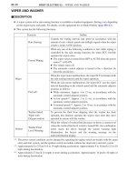
Service Tip
When brake control system is activated, the brake pedal could shudder, which is a normal occurrence
of the system in operation and should not be considered a malfunction.
CH-132
JBRAKE CONTROL SYSTEM (ABS with EBD, Brake Assist, TRC and VSC)
1. General
The brake control system (ABS with EBD, brake assist, TRC and VSC) of new Camry has the following
functions:
Function
Outline
ABS
(Anti-lock Brake System)
The ABS helps prevent the wheels from locking when the brakes are
applied firmly or when braking on a slippery surface.
EBD
(Electronic Brake
force Distribution)
The EBD control utilizes ABS, realizing the proper brake force distribution
between front and rear wheels in accordance with the driving conditions.
In addition, during cornering braking, it also controls the brake forces of
right and left wheels, helping to maintain the vehicle behavior.
Brake Assist
(Electrical Type)
The primary purpose of the brake assist is to provide an auxiliary brake
force to assist the driver who cannot generate a large brake force during
emergency braking, thus helping draw the vehicle’s brake performance.
TRC
(Traction Control)
The TRC system helps prevent the drive wheels from slipping if the driver
presses the accelerator pedal excessively when starting off or accelerating
on a slippery surface.
VSC
(Vehicle Stability Control)
The VSC system helps prevent the vehicle from slipping sideways as a
result of strong front wheel skid or strong rear wheel skid during cornering.
CH
CHASSIS – BRAKE
02KCH35TE
Speed Sensors
Stop Light Switch
Stop Light Control Relay*
1
Stop Light*
1
VSC Warning Buzzer
Combination Meter
Speedometer
Skid Control
ECU
Brake Actuator
Solenoid Relay
Master Cylinder Cut
Solenoid Valve (2)
Solenoid Valve (8)
Master Cylinder
Pressure Sensor
Pump Motor
Motor Relay
Motor Cut Relay
From Battery
DLC3
Parking Brake Switch
Main Body ECU
Yaw Rat e &
Deceleration Sensor
Steering Angle
Sensor
CAN
(CAN No.2 Bus)
CAN Gateway ECU
Distance Control
ECU*
1
Millimeter Wave
Radar Sensor*
1
Crankshaft
Position Sensor
Accelerator Pedal
Position Sensor
Neutral Start
Switch
Engine ECU
Throttle Body
Throttle Position Sensor
Throttle Control Motor
Combination Meter
ABS Warning Light
Slip Indicator Light
Brake System Warning Light
VSC Warning Light*
3
Master Warning Light*
2
Multi-information Display*
2
CAN
(CAN No.1 Bus)
CH-133
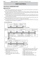
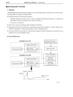
2. System Diagram
"
Model with ADVICS brake actuator
A
*
1
: Models with dynamic radar type cruise control system
*
2
: Models with multi-information display
*
3
: Models without multi-information display
CHASSIS – BRAKE
02KCH36TE
Speed Sensor (4)
Stop Light Switch
VSC Warning Buzzer
Combination Meter
Speedometer
Skid Control
ECU
Brake Actuator
Solenoid Relay
Master Cylinder Cut
Solenoid Valve (2)
Reservoir Cut
Solenoid Valve (2)
Solenoid Valve (8)
Master Cylinder
Pressure Sensor
Pump Motor
Motor Relay
From Battery
DLC3
Yaw Rate & Lateral
Acceleration Sensor
Steering
Angle Sensor
CAN (CAN No.1 Bus)
Parking Brake Switch
Main Body ECU
Crankshaft
Position Sensor
Accelerator Pedal
Position Sensor
Neutral Start
Switch
Engine ECU
Throttle Body
Throttle Position Sensor
Throttle Control Motor
Combination Meter
ABS Warning Light
Slip Indicator Light
Brake System Warning Light
Master Warning Light
Multi-information Display
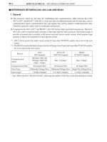
CH-134
"
Model with Bosch brake actuator
A
CH
CHASSIS– BRAKE
D13N68
Master Cylinder
Pressure Sensor
Signal
Skid Control
ECU
The fluid pressure is increased
by the brake actuator
With Brake Assist
D13N67
Without Brake Assist*
170CH18
Braking
Force
With Brake Assist
Without Brake Assist
Time
CH-135
3.Outline of EBD Control Function
The detailed outline is the same as that of brake control system (ABS with EBD). For details, see page
CH-122.
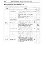
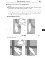
4. Outline of Brake Assist
D The brake assist in combination with ABS help to improve the vehicle’s brake performance.
D The brake assist interprets a quick push of the brake pedal as emergency braking and supplements the brake
power applied if the driver has not stepped hard enough on the brake pedal. In emergencies, some drivers,
especially inexperienced ones, often panic and do not apply sufficient pressure on the brake pedal.
D A key feature of brake assist system is that the timing and the degree of braking assistance are designed
to help ensure that the driver does not discern anything unusual about the braking operation. When the
driver intentionally eases up on the brake pedal, the system reduces the amount of assistance it provides.
D Based on the signals from the master cylinder pressure sensor, the skid control ECU calculates the speed
and the amount of the brake pedal application and then determines the intention of the driver to make an
emergency braking. If the skid control ECU determines that the driver intends the emergency braking, the
system activates the brake actuator to increase the brake fluid pressure, which increases the braking force.
"
In case that the driver’s depressing force is small when applying emergency braking
A
*: The basic performance of the brake is the same as of the model with the brake assist
CHASSIS – BRAKE
02KCH37Y
Without TRC System
With TRC System
Slippery Surface
Slippery Surface
Brake Actuator
with Skid Control
ECU
Brake
the slipping
drive-wheel
Engine ECU
D Regulating the throttle to
control the engine output
CH-136
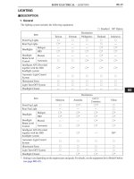
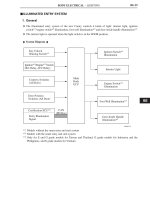
5. Outline of TRC Function
D If the driver presses the accelerator pedal aggressively when initially acceleration or when accelerating
on a slippery surface, the drive wheels could slip due to the excessive amount of torque that is generated.
By applying hydraulic brake control to the drive wheels and regulating the throttle to control the engine
output, the TRC helps minimize the slippage of the drive wheels, thus generating the drive force that is
appropriate for the road surface conditions.
D For example, a comparison may be made between two vehicles, one with the TRC function and the other
without. If the driver of each vehicle operates the accelerator pedal in a rough manner while driving over
a surface with different surface friction characteristics, the drive wheel on the slippery surface could slip
as illustrated. As a result, the vehicle could become unstable.
However, when the vehicle is equipped with the TRC function, the skid control ECU instantly determines
the state of the vehicle and operates the brake actuator in order to apply the brake of the slipping drive
wheel. Furthermore, the engine ECU receives the signals from the skid control ECU and regulates the
throttle in order to control the engine output. Thus, this function can constantly maintain a stable vehicle
posture.
"
Driving condition on road with different surface friction characteristics
A
CH
CHASSIS – BRAKE
189CH100
Front Wheel Skid Tendency
151CH17
Rear Wheel Skid Tendency
151CH19
Actual Locus of Travel
(Actual Yaw Rate)
Locus of Travel
Based on the
Target Yaw Rate
CH-137
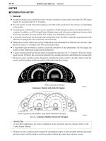
6. Outline of VSC Function
General
The followings are two examples that can be considered as circumstances in which the tires exceed their
lateral grip limit.
The VSC function is designed to help control the vehicle behavior by controlling the motive force and the
brakes at each wheel when the vehicle is under one of the conditions indicated below.
D When the front wheels lose grip in relation to the rear wheels (front wheel skid tendency).
D When the rear wheels lose grip in relation to the front wheels (rear wheel skid tendency).
Method for Determining the Vehicle Condition
To determine the condition of the vehicle, sensors detect the steering angle, vehicle speed, vehicle’s yaw
rate, and the vehicle’s lateral acceleration, which are then calculated by the skid control ECU.
1) Determining Front Wheel Skid
Whether or not the vehicle is in the state of
front wheel skid is determined by the
difference between the target yaw rate and the
vehicle’s actual yaw rate.
When the vehicle’s actual yaw rate is smaller
than the yaw rate (a target yaw rate that is
determined by the vehicle speed and steering
angle) that should be rightfully generated
when the driver operates the steering wheel, it
means the vehicle is making a turn at a greater
angle than the locus of travel.
Thus, the skid control ECU determines that
there is a large tendency to front wheel skid.
CHASSIS – BRAKE
151CH18
Direction of Travel of the Vehicle’s
Center of Gravity
Slip Angle
Movement of Vehicle
161ES30
Braking Force
Control Moment
Braking Force
Making a Right Turn
204CH15
Control Moment
Braking Force
Making a Right Turn
CH-138
2) Determining Rear Wheel Skid
Whether or not the vehicle is in the state of
rear wheel skid is determined by the values of
the vehicle’s slip angle and the vehicle’s slip
angular velocity (time-dependent changes in
the vehicle’s slip angle). When the vehicle’s
slip angle is large, and the slip angular
velocity is also large, the skid control ECU
determines that the vehicle has a large rear
wheel skid tendency.
Method for VSC Operation
When the Skid Control ECU determines that the vehicle exhibits a tendency to front wheel skid or rear wheel
skid, it decreases the engine output and applies the brake of a front or rear wheel to control the vehicle’s
yaw moment.
The basic operation of the VSC is described below. However, the control method differs depending on the
vehicle’s characteristics and driving conditions.
1) Dampening a Strong Front Wheel Skid
When the skid control ECU determines that
there is a large front wheel skid tendency, it
counteracts in accordance with the extent of
that tendency. The skid control ECU controls
the engine output and applies the brakes of the
front wheels and rear wheel of the inner circle
of the turn in order to help restrain the front
wheel skid tendency.
2) Dampening a Strong Rear Wheel Skid
When the skid control ECU determines that
there is a large rear wheel skid tendency, it
counteracts in accordance with the extent of
that tendency. It applies the brakes of the front
wheel of the outer circle of the turn, and
generates an outward moment of inertia in the
vehicle, in order to restrain the rear wheel skid
tendency. Along with the reduction in the
vehicle speed caused by the braking force, the
excellent vehicle’s stability is ensured.
In some cases, the skid control ECU applies
the brake of the rear wheels, as necessary.
CH
CHASSIS – BRAKE
189CH71
Braking
Operation
Buzzer
Sounds
Throttle Valve
Closed
D Throttle Valve Closed
D Braking Operation
Set Vehicle Distance
CH-139
7. Outline of Brake Control
(Operating of Dynamic Radar Type Cruise Control System)*
During dynamic radar type cruise control system operation, if the distance to the vehicle being driven ahead
is reduced, and if a sufficient deceleration cannot be attained by fully closing the throttle valve, the skid
control ECU activates the brake actuator to apply the brakes according to the distance control ECU’s request.
As a result, the stoplights illuminate.
If further deceleration is required, the system sounds a VSC warning buzzer to alert the driver to apply the
brakes. This warning buzzer is the same buzzer that the VSC system uses.
*: Models with dynamic radar type cruise control system
CHASSIS – BRAKE
02KCH38TE
Multi-information Display
ABS Warning Light
Slip Indicator Light
Master Warning Light
Brake System
Warning Light
Distance Control
ECU*
1
VSC Warning
Buzzer
Stop Light Switch
DLC3
Steering Angle
Sensor
Yaw Rate & Deceleration Sensor
Speed Sensors
Engine ECU*
4
Brake Actuator
D Skid Control ECU
D Master Cylinder Pressure Sensor
D Solenoid Relay
D Motor Relay*
3
Speed Sensors
Engine Room R/B
D Motor Relay*
2
D Motor Cut Relay*
2
Engine ECU*
5
VSC Warning Light
ABS Warning Light
Models with Multi-information Display Models without Multi-information Display
LHD Models
CH-140
8. Layout of Main Components
*
1
: Models with dynamic radar type cruise control system
*
2
: Model with ADVICS brake actuator
*
3
: Model with Bosch brake actuator
*
4
: Model with 2GR-FE engine
*
5
: Model with 1AZ-FE engine and 2AZ-FE engine
CH
CHASSIS – BRAKE
CH-141
9. Function of Main Components
Component Function
ABS Warning Light
Lights up to alert the driver when the skid control ECU detects the
malfunction in the ABS, EBD or Brake Assist system.
Slip Indicator Light
D Blinks to inform the driver when the TRC system or the VSC
system is operated.
Combination
Meter
Brake System
Warning Light
D Lights up together with ABS warning light to alert the driver when
the skid control ECU detects the malfunction in the EBD control.
D Lights up to inform the driver when the parking brake is ON or the
brake fluid level is low.
Meter
VSC Warning Light*
1
Lights up to alert the driver when the skid control ECU detects the
malfunction in the TRC or VSC system.
Master Warning Light*
2
Lights up to alert the driver when the skid control ECU detects the
malfunction in the TRC or VSC system.
Multi-information
2
Displays a warning massage to alert the driver when the skid control
Display*
2
py g g
ECU detects a malfunction in the TRC or VSC system.
Engine ECU
D Sends the throttle valve angle signal, accelerator pedal position
signal, engine speed signal, and shift lever position signal to the
skid control ECU.
D Receives the signal of throttle control request from the skid control
ECU.
Parking Brake Switch Detects when the parking brake lever is pulled up.
Speed Sensors Detects the wheel speed of each 4 wheels.
Stop Light Switch Detects the brake pedal depressing signal.
Distance Control ECU*
3
Transmits a signal to the skid control ECU via the engine ECU, in order
to activate brake control when the distance control ECU has
determined that the distance to the vehicle being driven ahead has been
shortened based on signals from the millimeter wave radar sensor.
Brake Actuator
Changes the fluid path based on the signals from the skid control ECU
during the operation of the ABS with EBD & brake assist & TRC &
VSC system, in order to control the fluid pressure that is applied to the
wheel cylinders.
Master Cylinder
Pressure Sensor
Assembled in the brake actuator and detects the master cylinder
pressure.
Skid Control ECU
Judges the vehicle driving condition based on signals from each
sensor, and sends brake control signal to the brake actuator.
Solenoid Relay Supply power to the solenoid valves.
Motor Relay*
4
Supply power to the pump motor in the brake actuator.
VSC Warning Buzzer
Emits an intermittent sound to inform the driver that the skid control
ECU detects the strong front skid tendency or strong rear skid
tendency.
Yaw Rate & Deceleration Sensor*
5
D Detects the vehicle’s yaw rate.
D Detects the vehicle’s longitudinal and lateral acceleration.
Yaw Rate & Lateral Acceleration
Sensor*
4
D Detects the vehicle’s yaw rate.
D Detects the vehicle’s lateral acceleration.
Steering Angle Sensor Detects the steering direction and angle of the steering wheel.
Motor Relay*
5
Supply power to the pump motor in the brake actuator.
Motor Cut Relay*
5
Cut the power to the pump motor in the brake actuator.
*
1
: Models without multi-information display
*
2
: Models with multi-information display
*
3
: Models with dynamic radar type cruise control system
*
4
: Model with Bosch brake actuator
*
5
: Model with ADVICS brake actuator
CHASSIS – BRAKE
285CH28
Master Cylinder
Brake Actuator
Port (A)
(1)
Port (C)
Port (D)
(3)
Port (H)
(4)
Port (G)
(7) (8)
Front Left Rear Right
Pumps
Pressure
Regulator
Valves
Reservoirs
Master Cylinder
Pressure Sensor
Port (B)
Port (E)
(2)
Port (F)
(5)
Port (I)
(6)
(9)
(10)
Port (J)
Rear Left Front Right
CH-142
10. Brake Actuator
D The brake actuator consists of the actuator portion, skid control ECU, relays.
D Models with ADVICS brake actuator consists of 10 solenoid valves, 1 pump motor, 2 pumps, 2 pressure
regulator valves, 2 reservoirs and 1 master cylinder pressure sensor.
D Models with Bosch brake actuator consists of 12 solenoid valves, 1 pump motor, 2 pumps, 2 reservoirs
and 1 master cylinder pressure sensor.
"
Hydraulic Circuit (Model with ADVICS brake actuator)
A
Component
(1), (2) Master Cylinder Cut Solenoid Valve
(3), (4), (5), (6) Pressure Holding Valve
(7), (8), (9), (10) Pressure Reduction Valve
CH
CHASSIS – BRAKE
025CH74Y
Master Cylinder
Brake Actuator
Master Cylinder
Pressure Sensor
(1)
(2)
(5) (6)
(9) (10)
Front Right Rear Left
Pumps
Reservoirs
(3) (4)
(7) (8)
(11) (12)
Rear Right Front Left
CH-143
"
Hydraulic Circuit (Model with Bosch brake actuator)
A
Component
(1), (4) Master Cylinder Cut Solenoid Valve
(2), (3) Reservoir Cur Solenoid Valve
(5), (6), (7), (8) Pressure Holding Valve
(9), (10), (11), (12) Pressure Reduction Valve
CHASSIS – BRAKE
285CH29
Master Cylinder
Brake Actuator
Port (A)
(1)
Port (C)
Port (D)
(3)
Port (H)
(4)
Port (G)
(7)
(8)
Rear Left Rear Right
Pumps
Pressure
Regulator
Valves
Reservoirs
Master Cylinder
Pressure Sensor
Port (B)
Port (E)
(2)
Port (F)
(5)
Port (I)
(6)
(9) (10)
Port (J)
Front Left Front Right
CH-144
11. System Operation
Normal Braking Operation
During normal braking, all solenoid valves are remained OFF.
"
Hydraulic Circuit (Model with ADVICS brake actuator)
A
CH
CHASSIS – BRAKE
025CH75Y
Master Cylinder
Brake Actuator
Master Cylinder
Pressure Sensor
(1) (2)
(5) (6)
(9)
(10)
Front Right Rear Left
Pumps
Reservoirs
(3) (4)
(7)
(8)
(11)
(12)
Rear Right Front Left
CH-145
"
Hydraulic Circuit (Model with Bosch brake actuator)
A
CHASSIS – BRAKE
Port A
Pressure Holding
Solenoid Valve
Port B
Pressure Reduction
Solenoid Valve
To Wheel
Cylinder
To
Reservoir
and Pump
From Wheel
Cylinder
D13N69 D13N70 D13N71
CH-146
ABS with EBD Operation
Based on the signals received from the 4 wheel speed sensors and yaw rate & deceleration sensor*
1
/yaw
rate & lateral acceleration sensor*
2
, the skid control ECU calculates each wheel speed and deceleration, and
checks wheel slipping condition. According to the slipping condition, the ECU controls the pressure
holding solenoid valve and pressure reduction solenoid valve in order to adjust the fluid pressure of each
wheel cylinder in the following three modes: pressure reduction, pressure holding, and pressure increase
modes.
*
1
: Model with ADVICS brake actuator
*
2
: Model with Bosch brake actuator
Not Activated
Normal Braking — —
Activated Pressure Increase Mode Pressure Holding Mode Pressure Reduction Mode
Hydraulic Circuit
Pressure Holding
Valve (Port A)
OFF/Open ON/Close ON/Close
Pressure
Reduction
Valve (Port B)
OFF/Close OFF/Close ON/Open
Pressure Increase Hold Reduce