Ô tô Camry 3.5Q - Phần 1 - P1
Bạn đang xem bản rút gọn của tài liệu. Xem và tải ngay bản đầy đủ của tài liệu tại đây (61.09 KB, 2 trang )
BODY ELECTRICAL – MULTIPLEX COMMUNICATION
BODY ELECTRICAL
02KBE01Y
CAN
Gateway
ECU*
1
AFS ECU*
2
Seat Belt
Control ECU*
3
Distance Control
ECU*
4
Engine ECUA/C ECU
Skid Control
ECU
Meter ECU
Steering Angle
Sensor*
5,6
Yaw Rate &
Deceleration*
5
/Lateral
Acceleration*
6
Rate Sensor
Active Control
Engine Mount ECU*
7
Airbag Sensor
Assembly*
8
DLC3
Main
Body
ECU
Clearance
Sonar ECU*
9
Seat ECU*
10
(for Driver)
Mayday ECU*
11
Mirror ECU*
10
Certification
ECU*
12
Tilt & Telescopic
ECU*
10
CAN
(CAN No.2 Bus)
CAN
(CAN No.1 Bus)
CAN
(MS Bus)
*
1
:Installed only when CAN No.2 bus is used
*
2
:Models with intelligent AFS
*
3
:Models with the pre-crash safety system
*
4
:Models with the dynamic radar type cruise
control system
*
5
:Except 2AZ-FE engine models with vehicle
stability control (VSC) system for Australia and
G.C.C. Countries
*
6
:2AZ-FE engine models with vehicle stability control
(VSC) system for Australia and G.C.C. Countries
*
7
:Models with the power tilt & power telescopic
column
*
8
:Models with SRS airbag system
*
9
:Models with the Toyota parking assist system
*
10
:Models with the memory system
*
11
:Models with the Toyota Link system
*
12
:Models with the smart entry and start system
BE-4
MULTIPLEX COMMUNICATION
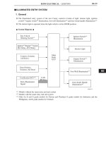
JDESCRIPTION
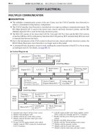
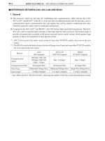
DThe multiplex communication system of the new Camry uses the CAN (Controller Area Network) to
achieve a streamlined wiring harness configuration.
DThe CAN (Controller Area Network) is classified into two types according to communication speed. The
HS (High Speed)-CAN is used for the power train, chassis and body electrical systems, and the MS
(Medium Speed)-CAN is used for the body electrical system.
DThe HS-CAN consists of two buses (the CAN No.1 bus and CAN No.2 bus) and the MS-CAN consists
of one bus (MS bus). ECUs with gateway functions (the CAN gateway ECU and main body ECU)are used
to transmit data between the buses.
DDue to the introduction of the CAN system for the power train, chassis and body electrical systems, the
BEAN (Body Electronics Area Network) is no longer used on this model.
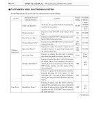
DA customized body electronics system is used, enabling the control functions of the ECUs to be set using
an intelligent tester II. For details, see page BE-14.
"
System Diagram
A
BE
BODY ELECTRICAL – MULTIPLEX COMMUNICATION
240BE03
240BE05
Frame
Data
1
0
Header End Message
Battery
Serial Communication Data
Switch
ECU
On On
Off
ECU
Light
Motor
Heater
Solenoid
BE-5
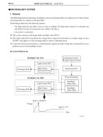
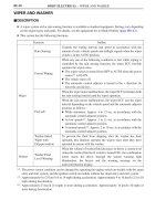
— REFERENCE —
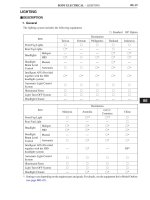
MPX communication uses serial communication data that consists of bits and frames in order to exchange
information among the various ECUs. This allows a reduction of the amount of wiring on the vehicle.
D A bit is the basic unit of communication that is used to represent information. A bit is represented by binary
values of “0” or “1”.
D A frame is a body of data that is transmitted together. A frame contains a header that indicates the
beginning, and an end message that indicates the end.
"
Conceptual Drawing
A