Hộp số xe ô tô HuynDai HD120
Bạn đang xem bản rút gọn của tài liệu. Xem và tải ngay bản đầy đủ của tài liệu tại đây (1.44 MB, 95 trang )
TRANSMISSI
ON
(M6S6)
GENERAL ............................................................................. TMa - 2
SPECIFICATIONS ................................................................. TMa - 3
SERVICE STANDARDS ........................................................ TMa - 4
SPECIAL TOOLS .................................................................. TMa - 7
SERVICE PROCEDURE ....................................................... TMa - 8
TROUBLESHOOTING .......................................................... TMa-42
TMa-2
-
TRANSMISSION (M6S6)
GENERAL
TRANSMISSION PROPER
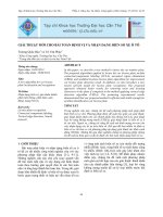
The transmission changes the torque produced by the engine to a
torque the vehicle requires. The torque, or drive power, is increased
or decreased by shifting several groups of gears.
Since the engine always turns in one direction, the transmission
also performs the function of changing the direction of rotation so
the vehicle can be backed.
NOTE:
This illustration shows a 5-speed transmission.
Shift fork
Synchromesh
Drive pinion
Costant mesh gear
5th
4th
2nd
3rd
1st
Rev.
5th
4th
1st
2nd
3rd
Rev.
22AA0375
TMa-3SPECIFICATONS
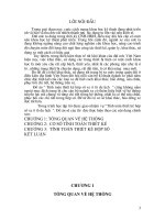
The transmission gears are kept in constant mesh with the drive
pinion by the constant-mesh gears, main shaft gears, and counter
shaft gears.
The rotating motion imparted by the drive pinion to the constantmesh
gears is transmitted to all main shaft gears which turn freely. When
the gearshift lever, the synchromesh function causes the synchronizer
sleeve to mesh with a gear to change the speed of rotation from the
pinion and transmit it to the rear axle.
The constant-mesh slide design is employed between the 1st and
reverse gear.
<Pin type>
22AA0376
22AA0312
5th gear
Shifting key
spring
Synchronizer hub
SYNCHRONIZER ASSEMBLY
<Key type>
Synchronizer
sleeve
Synchronizer ring
Synchronizer cone
4th gear
Shifting key
Type
K360
6.453
3.604
1.813
1.000
0.803
-
6.453
5.5
Floor shift, remote control type
SPECIFICATONS
TRANSMISSION PROPER
1st
2nd
3rd
4th
5th
6th
Rev.
GEAR RATIO
Oil capacity (with P.T.O)
Transmission control
Synchronizer ring
Sleeve
Synchronizer
stem
Synchronizer cone
2nd gear
Sunchronizer hub
Shifting pin
Shifting ball
Shifting spring
TMa-4
-
TRANSMISSION (M6S6)
SERVICE STANDARDS
SERVICE STANDARDS TABLE
Nominal value
(Basic diameter in [ ])
Limit
1st gear
2nd gear
3rd gear
4th gear
5th gear (drive pinion and
constant-mesh gear)
Reverse gear Counter shaft
Main shaft
1st gear (main shaft)
2nd gear (main shaft)
3rd gear (main shaft)
4th gear (main shaft)
Reverse gear (main shaft)
Reverse gear (reverse gear shaft)
Play in diametric direction after assembly of
reverse gear needle bearing
Main
shaft
Play in diametric direction after
assembly of pilot bearing
0.08 to 0.20
0.08 to 0.20
0.09 to 0.21
0.09 to 0.21
0.04 to 0.17
0.08 to 0.20
0.09 to 0.21
0.15 to 0.35
0.25 to 0.40
0.15 to 0.35
0.2 to 0.9
-
-
4.75 to 4.95
0.05 to 0.20
T0.0069 to L0.088
0.052 to 0.148
1.45 to 1.85
Replace
Check for damaged
tooth surface
Replace gear or washer
Replace defective parts
Replace defective parts
Replace
Replace
Remedy and remarks
Maintenance item
2nd and 3rd synchronizer assembly
synchronizer ring to main shaft 3rd
2nd gear assembly synchronizer
cone clearance
Fit between 2nd and 3rd synchronizer
hub and main shaft in turning
direction
0
0.052 to 0.148
T0.005 to L0.107
1.5
0.3
0.2
Unit: mm
Backlash
End play
Syn-
chro-
mesh
key
type
Synchronizer ring keyway to shifting
key clearance
Synchronizer hub keyway to shifting
key clearance
Fit between synchronizer hub and
main shaft in turning direction
Play between synchronizer hub and
synchronizer sleeve in turning
direction
Synchronizer ring to main shaft 4th
gear assembly gear cone clearance
0.5
0.5
1.2
0.12
0.12
5.8
0.5
0.2
0.3
0.2
Syn-
chro-
mesh
key
type
TMa-5SERVICE STANDARDS
Nominal value
(Basic diameter in [ ])
Maintenance item Limit
-0.10
0.12
0.3
1.0
0.2
0.06
0.04
7.3 N (7.4 kgf)/
27.6
0.15
0.36
1.0
0.6
0.6
0.6
42 N (4.3 kgf)/
45.4
1st gear
2nd gear
3rd gear
4th gear
Reverse gear
Shift fork to synchronizer
sleeve clearance
Tilt of shift fork claw
Alignment or bend of
shift rail
1st and Rev.
2nd and 3rd
4th and 5th
1st and Rev.
2nd and 3rd
4th and 5th
1st and Rev.
4th and 5th
2nd and 3rd
Load/installed
length
1st and Rev. return spring
Speedometer gear bushing to speedometer
gear clearance
Backlahs between speedometer gear and
speedometer worm
Ball stud to housing clearance
Housing bushing to pipe A clearance
Front cross shaft to bushing clearance
Rear cross shaft to bushing
Spring
Load/installed
length
0.1 or less
O.D.
-0.030
-0.043
[55]
-0.030
-0.043
Main
shaft
Lower
gear
shift
Upper
gear
shifter
Speedo-
meter
gear
Trans-
mission
control
-
Replace
Replace
Replace
Corret or replace
Replace
Replace
Replace
Replace ball stud or
housing, whichever
is worn
Replace bushing
Replace bushing
Replace bushing
Replace
Remedy and remarks
2nd gear bearing sleeve
3rd gear bearing sleeve
4th gear bearing sleeve
Clearance in diametric
direction after assembly
of main shaft needle
roller bearing
Play between synchronizer sleeve and main
shaft in turning direction
0.03 or less
0.02 or less
85 N (8.7kgf)/
27.6
[12] 0.02 to 0.07
0.13 to 0.29
0.10 to 0.40
0.07 to 0.17
0.07 to 0.17
0.02 to 0.25
52 N (5.3 kgf)/
45.4
0.052 to 0.148
0.3 to 0.5
[68]
Replace
Replace defective
parts. If two needle
roller bearings are
used for a gear, use
bearings of the same
package color for
replacement
TMa-6
-
TRANSMISSION (M6S6)
TIGHTENING TORQUE TABLE
Clutch housing bolt
Gearshift upper mounting bolt
Gearshift lower mounting bolt
Gearshift fork set bolt
Drain plug and level plug
Main shaft front lock nut
Main shaft rear lock nut
Reverse shaft lock piece bolt
Rear cover and extension housing bolt
Backup lamp switch
Speedometer gear bushing
Mounting bolt of transmission (clutch housing)
onto engine (flywheel housing)
Counter shaft rear lock nut
Rear bearing retainer mounting
Jaw set bolt
Lock pin mounting nut
Support plate and shoe assembly or
dust cover mounting bolt
Front mechanism housing bolt
Select lever bolt
Gearshift lever bolt
Select rod and shift rod ball joint nut
Tighten ball joints
Location tightened
M16 x 2.0
M8 x 1.25
M8 x 1.25
M10 x 1.25
M20 x 1.5
M36 x 1.5
M27 x 1.5
M10 x 1.5
M10 x 1.5
M18 x 1.5
M27 x 1.5
M10 x 1.5
M36 x 1.5
M10 x 1.5
M14 x 1.5
M8 x 1.25
M10 x 1.5
M12 x 1.25
M12 x 1.25
M12 x 1.25
M8 x 1.25
M8 x 1.25
M10 x 1.25
Tightening torque
Nm (kgfm)
190 (19.2)
23 (2.3)
23 (2.3)
29 (3.0)
54 to 83 (5.5 to 8.5)
245 (25)
245 to 345 (25 to 35)
40 (4.1)
40 (4.1)
49 (5.0)
145 (15)
40 (4.1)
345 (35)
40 (4.1)
135 (13.6)
17 (1.7)
40 (4.1)
48 (4.9)
37 to 54 (3.8 to 5.5)
36 (3.7)
8.8 to 14 (0.9 to 1.4)
19 to 27 (1.9 to 2.8)
38 to 59 (3.9 to 6.0)
Screw size
O.D. x pitch (mm)
Transmission
proper
Transmission
control
TMa-7
SPECIAL TOOLS
Tool name
Shape
Use
Puller set Removal of drive pinion and
reverse shaft
Part No.
09431-83100
ASST0030
Unit: mm
SPECIAL TOOLS
TMa-8
-
TRANSMISSION (M6S6)
22AA1335
Inspection
plug
Drain
plug
22AA0381
Interlock switch
Return spring
SERVICE PROCEDURE
REMOVAL AND INSTALLATION OF TRANSMISSION
Key points for removal
1) Detach the control rod and associated parts around the
transmission.
2) Remove the power cylinder with hoses and pipes left attached.
3) Remove the propeller shaft.
4) Remove the drain plug and inspection plug to remove trans-
mission oil. On vehicles with full-power PTO, remove
transmission oil also from the PTO case.
5) When draining the transmission oil, check the oil for quantity,
quality, and metal chips and particles.
The drain plug is magnet and metal particles adhering to it
should be removed after the inspection.
22AA0004
Hub and release bearing
Clutch housing
Clutch booster
Dust plug
Cable bracket
Backup lamp switch
TMa-10
-
TRANSMISSION (M6S6)
22AA1337
Extension housing
22AA0310
(Vehicles with center parking brake)
Socket Wrench
TRANSMISSION ASSEMBLY
Disassembly
Disassembly Procedure
Using the Socket Wrench, remove the main shaft rear lock nut.
Clutch housing
(vehicles with C5 clutch)
Clutch housing
(vehicles with C6, C7 clutch)
Reverse gear
cover
Lower gear shifter
Companion
flange
Parking brake drum
Parking brake
assembly
Upper gear shifter
TMa-11SERVICE PROCEDURE
Reassembly
22AA1338
Drain plug
54 to 83 Nm
(5.5 to 8.5 kgfm)
NOTE
Apply sealant (THREEBOND 1105D or equivalent) to threads in
inspection and drain plugs.
Upper gear shifter
mounting bolt (8 places)
23 Nm (2.3 kgfm)
Lower gear shifter
mounting bolt (11 places)
23 Nm (2.3 kgfm)
Main shaft rear
lock nut
245 to 345 Nm
(25 to 35 kgfm)
Rear cover mounting
bolt (9 places)
40 Nm (4.1 kgfm)
Apply sealant
(THREEBOND 1104J
or equivalent
to mating surfaces
Apply sealant
(THREEBOND 1215J
or equivalent
to mating surfaces
Apply sealant
(THREEBOND 1215 or
equivalent
to mating surfaces
Inspection plug and drain plug
Inspection plug
54 to 83 Nm
(5.5 to 8.5 kgfm)
TMa-12
-
TRANSMISSION (M6S6)
Cluch housing
Drive pinion
22AA0666
190 Nm
(19.2 kgfm)
22AA0667
Vinyl Tape
22AA0015
Reassembly Procedure
1) To mount the clutch housing to the transmission case, using
the Vinly Tape.
2) Tighten the clutch housing mounting bolts in diagonal order
and uniformly, and finally tighten to specified torque.
Transmission
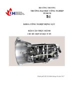
Inspection before disassembly
Before attempting to disassemble the transmission, measure the
backlash between gears and end play in each gear. If the
measurement exceeds the limit, replace the defective parts.
22AA0309
End play
NV 0.25 to 0.4
L 0.5
Backlash
NV 0.2 to 0.9
L 0.5
5th 4th 3rd 2nd 1st Rev.
End play
NV 0.09 to 0.21
L 0.5
Backlash
NV 0.09 to 0.21
L 0.5
End play
NV 0.15 to 0.35
L 0.5
Backlash
NV 0.08 to 0.20
L 0.5
Backlash
NV 0.09 to 0.21
L 0.5
Backlash
NV 0.04 to 0.17
L 0.5
TMa-13SERVICE PROCEDURE
Disassembly and inspection
o Check bearings for rotating condition.
o Check gears and splines for tooth contact, damage,
and flaking and missing tooth.
Play diametric
direction after assembly
L 0.12
Bend
NV 0.05 or less
L 0.1
Clearance
BD 13
NV 0.02 to 0.07
L 0.15
Tilt of claw
NV 0.1 or less
L 0.2
Clearance
NV 0.3 to 0.5
L 1.0
Bend
NV 0.3 or less
L 0.06
Bend
NV 0.02 or less
L 0.04
Clearance
NV 0.05 to 0.20
L 0.5
Clearance
NV 4.75 to 4.95
L 5.8
Play in turning direction
NV 0.052 to 0.148
L 0.3
Fit in counter shaft
in turning direction
NV T0.006 to L0.088
L 0.2
Clearance
NV 1.45 to 1.85
L 0.2
Play in diametric direction
after assembly
NV 0.105 to 0.150
L 0.3
8
32
1
M5S5, M6S5
24
4
11
29
22
5
2
20
19
18
3
21
26
36
35
34
33
31
20
25
6
12
23
13
14
7
16
17
10
15
9
27
30
28
10
Wear
Wear
VB43001
TMa-14
-
TRANSMISSION (M6S6)
25
Bearing
26
Bearing
27
Snap ring
28
Snap ring
29
Drive pinion assembly
30
Bearing
31. Rear bearing retainer
32
Snap ring
33
Bearing
34. Main shaft assembly
35. Counter shaft assembly
36. Transmission case
13
Synchronizer hub
14
Synchronizer ring
15
Counter shaft O.D. gear assembly
16. O.D. gear sleeve
17. Thrust washer
18. Reverse shaft lock piece
19
Reverse gear shaft
20. Reverse gear side washer
21
Reverse gear
22
Needle bearing
23
Snap ring
24
Snap ring
Disassembly sequence
1. Main shaft O.D. gear
2. O.D. shift shaft
3
O.D. shift lever
4
O.D. shift rail B
5. Set bolt
6
O.D. gearshift rail C
7
O.D. gearshift fork
8
Lock nut
9. Shifting key retainer
10. Shifting key spring
11
Synchronizer sleeve
12
Shifting key
2) Check O.D. shift rail B and O.D. gearshift rail C for alignment
or bend. (Half of the dial indicator reading is the bend.)
If the limit is exceeded, correct or replace the part.
For parts with an encircled number, refer to
Disassembly and Inspection Procedure that follows.
NOTE
1. Before disassembling the key type synchronizer, put matching mark at one location each in the
synchronizer hub and synchronizer sleeve where a key is inserted.
2. Before removing the main shaft assembly, extract the ball bearings at front and rear of the counter
shaft and let it fall down into the transmission case.
Disassembly and Inspection Procedure
1) Check the O.D. shift lever for alignment or bend.
If B is misaligned or bent exceeding the limit with reference to
A-A, replace the lever
A A A
VB43003
VB43005
TMa-15SERVICE PROCEDURE
7) Measure the clearance between the synchronizer ring and gear
cone of the counter shaft O.D. gear assembly. If the limit is
exceeded, replace the parts.
NOTE
Press the synchronizer ring evenly and take measurement
throughout the entire circumference.
VB43015
VB43013
VB43011
VB43009
VB43007
3) Using the special tool, Single Spanner, remove the lock nut.
<M5S6, M6S6>
4) Measure the clearance between the O.D. gearshift fork and
synchronizer sleeve and replace the parts if the clearance ex-
ceeds the limit.
At the same time, check the shift fork claw for tilt.
If defects are evident, correct or replace the parts.
5) Measure the clearance between the synchronizer hub keyway
and shifting key. If the clearance exceeds the limit, replace the
parts.
6) Measure the synchronizer ring keyway width and shifting key
width to calculate the clearance. If the clearance exceeds the
limit, replace the parts
Single Spanner
MH061555
O.D. gearshift fork
Synchronizer
sleeve
Shifting key
Synchronizer hub
Shifting key
Synchronizer
Synchronizer
ring
Feeler gauge
Counter shaft O.D.
gear assembly
TMa-16
-
TRANSMISSION (M6S6)
Synchronizer ring
Shifting key
22AA0996
22AA1148
22AA0301
22AA1344
22AA1345
Disassembly and Inspection Procedure
1) Mesure the synchronizer ring keyway width and shifting key
width to calculate the clearnce. If the clearance exceeds the
limit, replace the parts.
2) Before disassembling the reverse gear, check it for play in dia-
metric direction. If the play excceds the limit, replace the defec-
tive parts.
3) Remove the reverse gear shaft.
4) Remove the snap rings from the front end of the counter shaft.
5) Remove bearings from the front and rear ends of the counter
shaft.
TMa-17SERVICE PROCEDURE
10) Remove the bearing from the rear end of the main shaft.
22AA1346
22AA1347
22AA0317
22AA1342
22AA0141
Puller set
09431-83300
Puller set
09431-83100
Puller set
09431-83100
6) Remove the snap rings on the drive pinion side.
7) Remove the drive pinion assembly together with the bearings.
8) Remove the bearings from the drive pinion.
9) Remove the snap ring from the rear end of the main shaft.
TMa-18
-
TRANSMISSION (M6S6)
2) Drive the bearing into the drive pinion assembly. Then, fit the
snap rings into position.
NOTE:
Place the drive pinion assembly on a flat surface when
installing the bearing into it to prevent the drive pinion
assembly from being damaged.
40 Nm
(4.1 kgfm)
22AA1349
22AA0188
22AA0155
Dummy Bearing Re-
tainer
Dummy Bearing
Main Shaft Rear
Bearing Installer
22AA1351
Bearing
Snap ring
Drive
pinion
assembly
Drift
Reassembly
1) With supporting the front end of the main shaft drive the
bearings, to which snap rings have been attached, into the rear
end of the main shaft using special tool.
14
9
8
1
2
3
4
5
15
3
1817
13
12
11
10
6
7
16
TMa-19SERVICE PROCEDURE
7) Insert the reverse gear, to which the needle bearing and re-
verse gear side washer have been installed, from the side
washer have been installed, from the side and drive the re-
verse gear shaft into position with a plastic hammer. Then, se-
cure the shaft with the reverse shaft lock piece.
22AA0908
22AA1352
22AA1353
22AA1344
Oil hole
40 Nm
(4.1 kgfm)
Reverse shaft
lock piece
O-ring
Reverse gear
side washer
Reverse gear
side washer
Reverse
gear shaft
Reverse gear
22AA1354
Drift
Drift
Drift
3) Drive the bearing together with the drive pinion assembly into
position.
4) Hold the front end of the counter shaft with tools. Then, install
the bearing on the rear end with the groves outward.
5) Remove the tool from the front end of the counter shaft. Then
drive bearing, to which snap rings have been attached, into
position.
6) Fit the snap ring to secure the bearing in position.
TMa-20
-
TRANSMISSION (M6S6)
22AA1355
Oil groove
Synchronizer
sleeve
Synchronizer
hub
Stub
tooth
Keyway
22AA1356
22AA1000
Shifting key
spring
Shifting
key
Shifting key
spring
Shifting key
Synchronizer ring
Oil groove
22AA0993
22AA1357
Protrusions
8) Install the thrust washer so that its side having the oil groove
faces gear.
9) Mate the synchronizer hub with the synchronizer sleeve, en-
suring that the keyways at three places in the synchronizer
hub are aligned with stub teeth at three places (indicated by *
in Fig.) of the synchronizer sleeve.
NOTE
If the synchronizer hub and synchronizer sleeve are reused,
be sure to align the alignment marks when they are reas-
sembled together.
10) Fit shifting keys into keyways. Then, install the shifting key spring
so that gap between its ends is not located at the shifting key
position.
11) Face the synchronizer ring to the synchronizer hub side having
oil grooves. Then, align keyway and fit synchronizer ring to syn-
chronizer hub.
Next, mount the assembly onto the counter shaft.
12) Install the shifting key retainer to the synchronizer hub, making
sure that the protrusions at two places in the retainer are fitted
into the slots in hub.
TMa-21SERVICE PROCEDURE
14) After reassembly, check gears for backlash and end play.
NOTE
Check gears also for rotating condition.
22AA1358
345 Nm
(35 kgfm)
Tang
22AA1339
Single spanner
13) Tighten lock nut to specification.
NOTE
After torquing the lock nut, bend tangs at four places of
the shifting key retainer over the lock nut.
TMa-22 TRANSMISSION (M6S6)
MAIN SHAFT
Disassembly and Inspection
BD ... Basic Diameter
NV ... Nominal Value
L ... Limit
o Check bearings for rotating condition.
o Check gears and splines for tooth contact, damage, and
flaking and missing tooth.
Clearance
NV 0.05 to 0.20
L 0.5
Clearance
NV 4.75 to 4.95
L 5.8
Fit in main shaft in
turning direction
NV T0.006 to L0.088
L 0.2
Play in turning direction
NV 0.052 to 0.148
L 0.3
Play in diametric direction
after assembly
L 0.12
Play in diametric direction
after assembly
L 0.12
Play in diametric direction
after assembly
L 0.12
Play in diametric direction
after assembly
L 0.12
Play in diametric direction
after assembly
L 0.12
Fit in main shaft in
turning direction
NV T0.05 to L0.017
L 0.2
Play in turning direction
NV 0.052 to 0.148
L 0.3
Play in diametric direction
after assembly
L 0.2
Play in turning direction
NV 0.052 to 0.148
L 0.3
22AA0383
Clearance
NV 1.45 to 1.85
L 0.2
Clearance
NV 0
L 1.5
Clearance
NV 0
L 1.5
14
13
12
11
10
9
8
1
2
3
4
5
7
15
16
17
18
19
20
21
22
23
24
25
26
27
28
29
9
6
TMa-23
20. 2nd and 3rd synchronizer assembly
21. Main shaft 3rd gear bearing sleeve
22. 2nd and 3rd synchronizer hub
23. Main shaft 2nd gear assembly
24. Needle bearing
25. Main shaft 2nd gear bearing sleeve
26. 2nd gear thrust washer
27. Main shaft 1st and reverse gear
28. Needle bearing
29. Main shaft
Snap Ring Expander
22AA1359
Puller set
09431-83100
22AA1104
Disassembly Procedure
1) Using the Snap Ring Expander, remove the snap ring.
2) Using the special tool, Puller set, remove the pilot bearing.
SERVICE PROCEDURE
Disassembly sequence
1. 1st gear thrust washer
2. Main shaft 1st and reverse gear
3. Needle bearing
4. Synchronizer sleeve
5. Snap ring
6. Pilot bearing
7. Lock nut
8. Lock washer
9. Synchronizer ring
10. Shifting key spring
11. Synchronizer sleeve
12. Shifting key
13. Synchronizer hub
14. Main shaft 4th gear assembly
15. Needle bearing
16. Main shaft 4th gear bearing sleeve
17. 4th gear thrust washer
18. Main shaft 3rd gear assembly
19. Needle bearing
For parts with an encircled number, refer to Disassembly and
Inspection procedure that follows.
NOTE
1. Before disassembling the key type synchronizer, put
matching mark at one location each in the synchronizer
hub and synchronizer sleeve where a key is inserted.
2. Do not disassemble the 2nd and 3rd synchronizer assem-
bly of the pin type synchronizer, as its stem has been
staked over the ring. If it needs replacement, replace it as
an assembly.
TMa-24 TRANSMISSION (M6S6)
2) Measure the clearance between the synchronizer hub keyway
and shifting key. Replace parts if the clearance exceeds the
limit
Single Spanner
22AA0187
22AA575
Shifting key
Synchronizer hub
22AA1360
22AA0997
Bearing sleeve
3) Using the Single Spanner, loosen and remove the lock nut.
4) To remove each bearing sleeve, make use of the weight of gear;
i.e., lightly hit the main shaft against a lead plate.
NOTE
Be sure to use a lead plate to prevent main shaft end from
being damaged.
Inspection Procedure
1) Measure the play in diametric direction in each main shaft gear
and needle bearing.
If the play exceeds the limit, replace the needle bearing.
NOTE
1. If two needle bearings are used for one gear, use ones
of the same package color for replacement.
2. If replacement of the needle bearing does not correct
the excessive diametric play, check each bearing sleeve
(except those in 1st and reverse gear) and main shaft
gear and replace any defective parts.
TMa-25SERVICE PROCEDURE
Synchronizer ring
Shifting key
22AA0996
Synchronizer ring Gear cone
Feeler gauge
Main shaft 4th
gear assembly
22AA0998
Synchronizer ring
Synchronizer cone
Main shaft 3rd gear
assembly or main
shaft
2nd gear
assembly
Clearance
22AA0993
3) Measure the synchronizer ring keyway width and shifting key
width to calculate the clearance between the two. If the limit is
exceeded, replace parts.
4) Measure the clearance between thew synchronizer ring and
the gear cone of main shaft 4th gear assembly. If the clear-
ance exceeds the limit, replace parts.
NOTE
Press synchronizer ring evenly and take measurement
throughout the entire circumference.
5) Measure the clearance between the synchronizer ring of 2nd
and 3rd synchronizer assembly and the synchronizer cone of
main shaft 3rd/2nd gear assembly.
Replace parts if the clearance exceeds the limit.
TMa-26 TRANSMISSION (M6S6)
Assembly sequence
29→28→27→26→25→24→23→22→20→21→19→18→17→16→15→14→8→7→6→5→4→3→2→1
13→11→12→10→9
↑
For part with an encircled number, refer to Reassembly Procedure that followings.
245 Nm
(25 kgfm)
22AA1362
22AA1363
Main shaft 3rd
gear assembly side
Main shaft 4th gear
assembly side
Synchronizer hub
Synchro-
nizer
sleeve
Stub
tooth
Key way
Shifting key
spring
Shifting
key Shifting key
spring
Shifting key
22AA1000
22AA1356
Reassembly
Reassembly Procedure
1) Install the 4th gear thrust washer so that its side with a greater
contacting area faces the main shaft 3rd gear assembly.
2) Mate the synchronizer hub with the synchronizer sleeve, en-
suring that the keyways at three places in the synchronizer
hub are aligned with stub teeth at three places (indicated by *
in Fig.) of the synchronizer sleeve.
NOTE
If the synchronizer hub and synchronizer sleeve are reused,
be sure to align the alignment marks when they are reas-
sembled together.
3) Fit shifting key into keyways. Then, install the shifting key spring
so that the gap between its ends is not located at the shifting
key positions.
14
13
12
11
10
9
1
2
3
4
5
6
7
16 17
18
19
20
21
22
23
24
25
26
27
28
8
15
9
29