Xe ô tô BMW X5 E70 SM 02a_E70 Powertrain
Bạn đang xem bản rút gọn của tài liệu. Xem và tải ngay bản đầy đủ của tài liệu tại đây (188.84 KB, 9 trang )
Initial P
rint
Dat
e: 10/06
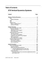
Table of Contents
Subject Page
Transfer Case, Axles and Output Shafts . . . . . . . . . . . . . . . . . . . . . . . .3
Changes . . . . . . . . . . . . . . . . . . . . . . . . . . . . . . . . . . . . . . . . . . . . . . . . . . . . . . .3
Transfer Box ATC700 . . . . . . . . . . . . . . . . . . . . . . . . . . . . . . . . . . . . . . . . . . .4
Coding Resistor . . . . . . . . . . . . . . . . . . . . . . . . . . . . . . . . . . . . . . . . . . . . . .5
Transfer Box Control Unit . . . . . . . . . . . . . . . . . . . . . . . . . . . . . . . . . . .5
Axle Drive . . . . . . . . . . . . . . . . . . . . . . . . . . . . . . . . . . . . . . . . . . . . . . . . . . . . . .6
Front Axle Gearbox VAG180A . . . . . . . . . . . . . . . . . . . . . . . . . . . . . . . . .6
Final Drive Unit HAG188K/188L . . . . . . . . . . . . . . . . . . . . . . . . . . . . . . .7
HAG188L . . . . . . . . . . . . . . . . . . . . . . . . . . . . . . . . . . . . . . . . . . . . . . . .7
Shafts . . . . . . . . . . . . . . . . . . . . . . . . . . . . . . . . . . . . . . . . . . . . . . . . . . . . . . . . .8
Propeller Shafts . . . . . . . . . . . . . . . . . . . . . . . . . . . . . . . . . . . . . . . . . . . . . .8
Output Shafts . . . . . . . . . . . . . . . . . . . . . . . . . . . . . . . . . . . . . . . . . . . . . . .9
E70 Powertrain
R
e
vision Dat
e:
2
E70 Powertrain
Powertrain
Model: E70
Production: From Start of Production
After completion of this module you will be able to:
• Describe the E70 Powertrain
• Understand changes to the X-drive Transfer Case
In many aspects, the transfer box, axle drive units, propeller shafts and the output shafts
in the E70 represent a further development of known components and technologies.
One of the main objectives of this development was to increase efficiency in the drive
train.
Changes
Changes and modifications have been made to the known transfer box, axle drive and
shaft systems in the E70:
• Re-engineered transfer box
• New front axle gearbox
• Final drive unit with optimized friction loss
• Propeller shaft fitted in a plug-on arrangement to the final drive unit
• Output shafts fitted in a plug-on arrangement to the final drive unit
3
E70 Powertrain
Transfer Case, Axles and Output Shafts
Transfer Box ATC700
The transfer box ATC700 is a further development of the ATC500 that was fitted in the
E53. The power is output via a chain to the propeller shaft to the front axle and appor-
tioned by a multi-disc clutch.
The torque transmission efficiency of the multi-disc package has remained the same
compared to the ATC500.
Only slight changes have been made compared to the ATC500.
• Installation position of coding resistor
• Optimized lifetime gear oil
• New ventilation system
• Transfer box control unit (VGSG).
4
E70 Powertrain
Index Explanation Index Explanation
1
Input
fr
om automatic gearbox
5
Multi-disc pack
age
2
Output to rear axle
6
Actuator lever with ball ram
3
Output to front axle
7
Chain
4
A
ctuat
or motor
8
Contr
ol wheel
Coding Resistor
The locking power characteristic of the multi-disc clutch can vary slightly due to the
mechanical tolerances in the production process. After measuring the actual locking
power on the clutch test rig, a resistor is fitted to the actuator motor with its value repre-
senting a reference regarding the progression of the locking power.
Every time the engine is started, the transfer box control unit measures the resistance and
correspondingly selects the optimum characteristic map for the installed transfer box.
To facilitate accessibility, the coding resistor is no longer fitted on the casing of the worm
drive but rather on the casing of the transfer box.
Transfer Box Control Unit
The transfer box control unit is known from the E60 and E90 all-wheel drive models.
It
has a new housing that is not water-tight. It is arranged under the luggage compart-
ment floor on the left next to the battery.
5
E70 Powertrain
Index Explanation Index Explanation
1
Transfer box casing
4
Flange to rear propeller shaft
2
W
orm gear casing
5
Coding resistor
3
Electric motor
6
Connectors