Effectiveness of Minimum Quantity Lubrication in Hard Milling of AISI H13
Bạn đang xem bản rút gọn của tài liệu. Xem và tải ngay bản đầy đủ của tài liệu tại đây (4.52 MB, 148 trang )
國立高雄應用科技大學
機械工程系
博士論文
AISI H13 硬銑削最少量潤滑有效性之研究
Effectiveness of Minimum Quantity Lubrication in Hard
Milling of AISI H13
Student: Do The Vinh (杜 勢 榮)
Advisor: Dr. Quang-Cherng Hsu (許光城 教授)
中華民國 106 年 6 月
i
AISI H13 硬銑削最少量潤滑有效性之研究
Effectiveness of Minimum Quantity Lubrication in Hard Milling of
AISI H13
研究生: 杜 勢 榮
指導教授: 許光城 教授
國立高雄應用科技大學
機械工程系
博士論文
A Dissertation Submitted to Institute of Mechanical Engineering
National Kaohsiung University of Applied Sciences
In Partial Fulfillment of the Requirements
For the Degree of Doctor of Philosophy
In Mechanical Engineering
June 2017
Kaohsiung, Taiwan, Republic of China
中華民國 106 年 6 月
ii
iii
中文摘要
最小量潤滑(MQL)可有效取代濕切及乾切製程,其應用於硬銑削可改善
表面光度、降低刀具磨耗、增加刀具壽命及降低切削溫度等優點。
本研究分為兩部分:第一部分以降低表面粗度值為品質目標利用田口
方法找出 AISI H13 於硬銑削下之最佳切削參數。本研究以槽銑加工進行
研究,採用 L9 直交表進行實驗配置並以訊噪比(S/N)及變異數分析(ANOVA)
分析最小量潤滑參數(切消液種類、壓力及流量)對表面光度的影響。結果
顯示其最佳參數為流量 50 ml/h 且壓力 3 kg/cm2 之水溶性切削液,其流量
與壓力貢獻度經變異數分析後依序為 68.13%及 30.19%。
在第二部分之研究主要基於表面粗糙度及切削力來驗證最小量潤滑之
效率,以乾切與最小量潤滑之切削力及表面粗糙度做比較,選用 L27 直交表
進行實驗規劃,運用反應曲面法及變異數分析來分析切削參數對切削力及
表面粗糙度的影響。結果顯示在乾切與最小潤滑的條件下進給率及切深皆
對表面粗糙度影響最大。切削力分量主要受切削深度影響其次為進給速率。
當切削條件為高切速、低進給與低切深且低硬度之材料即可獲得較良好的
表面粗糙度和最小的切削力。而最小量潤滑切削可提供較好的表面粗糙度
及降低刀具磨耗。以統計模型建立出預測模型用以預測乾切與最小量潤滑
條件下之切削力和表面粗糙度,其結果顯示最小量潤滑相較於乾切條件下
更具有顯著的效果。
關鍵字:最小量潤滑、優化、切削力、表面粗糙度、刀具磨耗、硬銑削、
田口方法、反應曲面法
iv
Effectiveness of Minimum Quantity Lubrication in Hard Milling of
AISI H13
Advisors: Prof. Quang-Cherng Hsu
Student:Do The Vinh
Institute of Mechanical Engineering
National Kaohsiung University of Applied Sciences
ABSTRACT
As a successful alternative to flood coolant processing and dry cutting, the
minimum quantity lubricant (MQL) has already been applied to hard milling for
improvement of surface finish, reduction of tool wear, an increase of tool life,
reduction of cutting temperature, etc.
This research was divided into two parts. In the first part, Taguchi method
was used to find the optimal values of MQL condition in the hard milling of AISI
H13 with consideration of improved surface roughness. Slot milling was selected
for the investigation as an operation that is commonly applied for machining of
the closed slots or pockets and grooves, etc. Taguchi’s L9 array was used to
design the experiments. The signal-to-noise (S/N) ratio and analysis of variance
(ANOVA) were utilized to analyze the influence of the performance
characteristics of MQL parameters (i.e., cutting fluid type, pressure, and fluid
flow) on surface finish. In the results section, the water-soluble oil lubricant, the
50 ml/h fluid flow and the 3 kg/cm2 pressures provided the best results for
surface roughness in hard-milling of AISI H13. Lubricant and pressure of MQL
condition are determined to be the most influential factors giving a statistically
significant effect on machined surfaces. The pressure factor contributed 68.13 %
and the lubricant factor contributed 30.19 % of the total effect. The effect of them
v
carried statistical significance. The three parameters of MQL conditions
explained 99.76 % of the variability in surface roughness.
In the second part, the research objective is to demonstrate the efficiency of
MQL based on certain process parameters such as surface roughness and cutting
force. A comparative analysis was done to prove the effectiveness of MQL
versus dry cutting. The characteristics of the cutting force and the surface
roughness obtained under dry cutting and MQL condition were experimentally
investigated. The experiments were conducted using the L27 orthogonal array of
Taguchi’s experimental design technique. The response surface methodology
(RSM) and analysis of variance (ANOVA) were employed for analysis the
influence of cutting parameters (i.e., cutting speed, feed rate, depth-of-cut and
hardness of work-piece) on the cutting force and the surface roughness. As the
result, under both cutting conditions (MQL and dry), feed rate and depth of cut
are the most influential variables regarding surface roughness. The cutting force
components get affected mostly by depth of cut followed by feed rate. Higher
cutting speed, lower feed rate, lower depth of cut and lower work-piece hardness
applied lead to good surface roughness and minimum cutting force. MQL cutting
provided better surface roughness and reduced tool wear. The difference of
values of cutting force components under two cutting conditions (MQL and dry)
is negligible in short machining time. The statistical models to predict cutting
force and surface roughness under dry cutting and MQL condition were
established. The results of the research showed the outstanding effectiveness of
MQL compared to dry cutting.
Keywords: Minimum quantity lubricant, optimization, cutting force, surface
roughness, tool wear, hard milling, Taguchi method, response surface
methodology.
vi
ACKNOWLEDGMENTS
The fulfillment of over four years of study at National Kaohsiung University
of Applied Sciences (KUAS) has brought me into closer relations with many
enthusiastic people who wholeheartedly devoted their time, energy, and support
to help me during my studies. Therefore, this is my opportunity to acknowledge
my great debt of thanks to them.
I wish to express my thanks and gratitude to my academic supervisor, Prof.
Dr. Quang-Cherng Hsu, for his continuous guidance, valuable advice, and
helpful supports during my studies. He has always been supportive of my
research work and gave me the freedom to fully explore the different research
areas related with MQL hard milling.
I would also like to thank Prof. Yung-Chou Kao, my first supervisor, for his
help and advice during my first study time at KUAS.
I wish to acknowledge my deepest thanks to President of KUAS and Office
of International Affairs for giving me a great opportunity, necessary scholarships
to study at KUAS and many enthusiastic helps during my time in KUAS. I am
also particularly grateful to Thai Nguyen University provided me unflagging
encouragement, continuous helps and support to complete this course.
My gratitude also goes to all of the teachers, Dean and staffs of Department
of Mechanical Engineering for their devoted teaching, great helping and
thoughtful serving during my study in ME.
I would also like to express my sincere gratitude to all of my colleagues at
the Precision and Nano Engineering Laboratory, Department of Mechanical
Engineering, KUAS. I would specially like to thank Mr. Ye Jhan Hong, Mr. Li
Wen Hsiung and Mr. Wei Lin for their great helps in my experimental process.
vii
I want to express my sincere thanks to all my Vietnamese friends in
KUAS for their helpful sharing and precious helping me over the past time.
I also wish to express my gratitude to all those who directly or indirectly
helped me during my study in KUAS.
Finally, my special thanks to my dad Đỗ Văn Kiểu and my mom Nguyễn Thị
Hà, to my brother Đỗ Minh Khoa, to my adorable wife Nguyễn Thị Nguyên, to
lovely little daughter Đỗ Khánh Linh, who is the most motivation for me over
years in Taiwan.
viii
CONTENTS
中文摘要 ......................................................................................................... iv
ABSTRACT ..................................................................................................... v
ACKNOWLEDGMENTS ............................................................................. vii
CONTENTS .................................................................................................... ix
LIST OF FIGURES ......................................................................................xiii
LIST OF TABLES ........................................................................................ xvi
NOMENCLATURE ....................................................................................xvii
Chapter 1 INTRODUCTION ........................................................................... 1
1.1 Motivation of the research ....................................................................... 1
1.2 Objective of the research ......................................................................... 4
1.3 Scopes of the research.............................................................................. 5
1.4 Organization of the Dissertation .............................................................. 6
Chapter 2 BACKGROUND ............................................................................. 8
2.1 Hard machining........................................................................................ 8
2.1.1 Overview .......................................................................................... 8
2.1.1.1 Concepts of hard machining ..................................................... 8
2.1.1.2 Advantages and disadvantages ................................................. 8
2.1.2 Basic operations in hard machining ................................................. 9
2.1.2.1 Hard turning ............................................................................. 9
2.1.2.2 Hard milling ........................................................................... 10
2.1.2.3 Other operations ..................................................................... 11
2.1.3 The characterization of hard machining ......................................... 13
ix
2.1.3.1 Cutting temperature ................................................................ 13
2.1.3.2 Surface roughness................................................................... 14
2.1.3.3 Cutting force ........................................................................... 15
2.1.3.4 Tool wear ................................................................................ 17
2.2 Cooling and lubrication in metal cutting ............................................... 19
2.2.1 Functions of cutting fluid ............................................................... 19
2.2.1.1 Cooling ................................................................................... 20
2.2.1.2 Lubrication ............................................................................. 22
2.2.2 Types of cutting fluid ..................................................................... 22
2.2.2.1 Neat cutting oil ....................................................................... 23
2.2.2.2 Soluble oil............................................................................... 24
2.2.2.3 Semisynthetic ......................................................................... 25
2.2.2.4 Synthetic ................................................................................. 26
2.2.3 Cooling/lubrication methods .......................................................... 26
2.2.3.1 Wet machining method .......................................................... 26
2.2.3.2 Dry machining method ........................................................... 28
2.2.3.3 Minimum quantity lubrication method .................................. 28
2.3 Minimum quantity lubrication ............................................................... 29
2.3.1 Introduction .................................................................................... 29
2.3.2 Principles of MQL system .............................................................. 30
2.3.3 The MQL systems .......................................................................... 32
2.3.4 The lubricant feeding forms in MQL ............................................. 33
2.3.4.1 Internal feeding form .............................................................. 33
2.3.4.2 External feeding form ............................................................. 34
x
2.3.5 Cutting fluids and parameters for MQL ......................................... 34
2.3.5.1 Fluid types for MQL............................................................... 34
2.3.5.2 Wetting of fluids ..................................................................... 35
2.3.5.3 Viscosity of fluids .................................................................. 35
2.3.5.4 Position of external nozzle ..................................................... 35
2.3.5.5 Fluid flow and air pressure ..................................................... 37
2.3.6 Benefits and limitations of MQL ................................................... 37
2.3.6.1 Benefits ................................................................................... 37
2.3.6.2 Limitations.............................................................................. 38
2.4 Literature review .................................................................................... 38
Chapter 3 RESEARCH METHODS .............................................................. 46
3.1 Taguchi method ..................................................................................... 46
3.2 Response surface methodology ............................................................. 50
3.3 Analysis of variance............................................................................... 52
Chapter 4 OPTIMIZATION OF MQL PARAMETERS ............................... 53
4.1 Design of experiment ............................................................................. 53
4.2 Experimental procedure ......................................................................... 56
4.3 Results and Discussions ......................................................................... 59
4.4 Summary ................................................................................................ 62
Chapter 5 EFFECTIVENESS OF MQL IN HARD MILLING .................... 63
5.1 Design of experiment ............................................................................. 63
5.2 Experimental procedure ......................................................................... 64
5.3 Results and Discussions ......................................................................... 66
5.3.1 The analysis of variance and the mathematical model of surface
roughness and cutting force under MQL conditions. .................... 68
xi
5.3.2 The analysis of variance and the mathematical model of surface
roughness and cutting force under dry conditions. ........................ 74
5.3.3 The comparative analysis. .............................................................. 81
5.4 User interface of calculation of response characteristics in hard milling
of AISI H13 ........................................................................................... 99
5.5 Summary .............................................................................................. 100
Chapter 6 CONCLUSION AND FUTURE WORKS ................................. 102
6.1 Conclusion ........................................................................................... 102
6.1.1 Optimization of MQL parameters ................................................ 102
6.1.2 Comparison between MQL and dry condition ............................. 103
6.2 Future works ........................................................................................ 104
LIST OF PUBLICATIONS ......................................................................... 106
SCIE papers ............................................................................................... 106
EI papers .................................................................................................... 106
International conferences ........................................................................... 106
APPENDICES ............................................................................................. 108
I. Technical Drawing ................................................................................. 108
II. Settings for machining program ............................................................ 108
III. NC program ......................................................................................... 109
IV. Code for the calculation of response characteristics ........................... 111
REFERENCE ............................................................................................... 119
xii
LIST OF FIGURES
Figure 1- 1 Research procedure .............................................................................. 6
Figure 2- 1 Hard turning process [33] .................................................................... 9
Figure 2- 2 Hard milling process [35] .................................................................. 10
Figure 2- 3 Hard boring operation [39] ................................................................ 11
Figure 2- 4 Hard hobbing operation [41] ............................................................. 12
Figure 2- 5 Dissipation of heat through chips during cutting process [43] .......... 13
Figure 2-6 Influences of cutting speed and work material on cutting
temperature[44] ............................................................................... 14
Figure 2- 7 Influence of cutting parameters on surface roughness[43] ................ 15
Figure 2- 8 The relationship between cutting force and hardness[4] ................... 16
Figure 2- 9 Relationship of cutting speed and cutting force components[50] ..... 16
Figure 2- 10 The influence of feed-rate and depth-of-cut on cutting force[43] ... 17
Figure 2- 11 Two basic wear types (a) crater wear, (b) flank wear [53] .............. 18
Figure 2- 12 Wear of end milling tool .................................................................. 19
Figure 2- 13 The distribution of the heat sources in cutting [57] ......................... 20
Figure 2- 14 Built-up edge [58] ............................................................................ 22
Figure 2- 15 Classification of cutting fluids in metal cutting [58] ....................... 23
Figure 2- 16 Machining with wet cutting method [67] ........................................ 27
Figure 2- 17 Benefits of dry cutting [15].............................................................. 28
Figure 2- 18 Metal-working fluid costs in metal machining [12] ........................ 30
Figure 2- 19 The ideal concept of MQL[72] ........................................................ 31
Figure 2- 20 Model of a simple MQL atomizer [70] ........................................... 31
Figure 2- 21 External and internal MQL system .................................................. 32
Figure 2- 22 External and internal lubrication feeding forms [73] ...................... 33
Figure 2- 23 The special drill tool with internal feed[71] .................................... 34
Figure 2- 24 Levels of wetting of fluids[71] ........................................................ 35
Figure 2- 25 Optimal position of external MQL nozzle for end milling [71] ...... 36
xiii
Figure 2- 26 The dead zone in feeding by external MQL nozzle [71] ................. 36
Figure 2- 27 The optimal angle of MQL nozzle [71] ........................................... 37
Figure 3- 1 The general Design Of Experiments process [87] ............................. 47
Figure 4- 1 Peanut oil ........................................................................................... 55
Figure 4- 2 Test - tube .......................................................................................... 55
Figure 4- 3 TiAlN coated-carbide end mill tool ................................................... 55
Figure 4- 4 Experimental set-up ........................................................................... 57
Figure 4- 5 Measurement of surface roughness by SJ-400 Mitutoyo surf-test
instrument ........................................................................................ 58
Figure 4- 6 Noga MC 1700 cooling system ......................................................... 58
Figure 4- 7 Statistical analysis by Minitab software ............................................ 59
Figure 4- 8 Effect of MQL parameters on surface roughness .............................. 60
Figure 5- 1 Experimental setup. ........................................................................... 65
Figure 5- 2 Using Minitab for statistical analysis ................................................ 66
Figure 5- 3 Optimization plot of surface roughness: a) Optimization for Ra-mql;
and, b) Optimization for Ra-dry...................................................... 82
Figure 5- 4 Plot of response surface for Ra-mql (other factors are held at middle
value) ............................................................................................... 83
Figure 5- 5 Plot of response surface for Ra-dry (other factors are held at middle
value) ............................................................................................... 84
Figure 5- 6 Optimization plot of cutting-force components: a) Optimization for
cutting force components of MQL conditions; and, b) Optimization
for cutting force components of dry conditions .............................. 86
Figure 5- 7 Plot of response surface for Fx-mql (other factors are held at middle
value) ............................................................................................... 87
Figure 5- 8 Plot of response surface for Fy-mql (other factors are held at middle
value) ............................................................................................... 88
Figure 5- 9 Plot of response surface for Fz-mql (other factors are held at middle
value) ............................................................................................... 89
xiv
Figure 5- 10 Plot of response surface for Fx-dry (other factors are held at middle
value) ............................................................................................... 90
Figure 5- 11 Plot of response surface for Fy-dry (other factors are held at middle
value) ............................................................................................... 91
Figure 5- 12 Plot of response surface for Fz-dry (other factors are held at middle
value) ............................................................................................... 92
Figure 5- 13 Comparison of Ra under dry- and MQL-cutting conditions. .......... 93
Figure 5- 14 Comparison of cutting-force components under dry and MQL
cutting conditions. ........................................................................... 95
Figure 5- 15 Comparison of experimental and predicted values of cutting force 96
Figure 5- 16 Comparison of dry and MQL condition in longer machining time
(cutting speed of 55m/min, feed rate of 0.02 mm/teeth, depth-of-cut
of 0.6mm, and hardness of 50HRC) ............................................... 98
Figure 5- 17 User interface of calculation of response characteristics ................ 99
Figure 5- 18 Resulting file of the program ........................................................... 99
Figure I Technical drawing for experimental process ........................................ 108
Figure II Settings for tool parameters ................................................................. 108
Figure III Settings for contour parameters ......................................................... 109
xv
LIST OF TABLES
Table 2. 1 Comparison of different cutting fluids[56] ......................................... 26
Table 2. 2 Some of the remarkable involved studies ........................................... 42
Table 3. 1 L9 orthogonal array .............................................................................. 48
Table 3. 2 L27 orthogonal array ............................................................................. 50
Table 4. 1 Chemical compositions of the AISI H13 steel (weight %). ................ 53
Table 4. 2 Material properties of AISI H13 steel ................................................. 53
Table 4. 3 Parameters and levels. ......................................................................... 56
Table 4. 4 Milling process information. ............................................................... 56
Table 4. 5 Technical information of milling tool. ................................................ 56
Table 4. 6 The surface roughness result and S/N ratio[93]. ................................. 59
Table 4. 7 Mean of S/N response for surface roughness. ..................................... 60
Table 4. 8 Analysis of variance for surface roughness (Ra) ................................ 61
Table 5. 1 Cutting parameters with levels ............................................................ 63
Table 5. 2 Hard-milling process information. ...................................................... 65
Table 5. 3 Information about the MQL process. .................................................. 65
Table 5. 4 Experimental results for surface roughness and cutting force
components. .................................................................................... 67
Table 5. 5 Analysis of Variance for Ra-mql......................................................... 69
Table 5. 6 Analysis of Variance for Fx-mql ......................................................... 70
Table 5. 7 Analysis of Variance for Fy-mql ......................................................... 71
Table 5. 8 Analysis of Variance for Fz-mql ......................................................... 72
Table 5. 9 Analysis of Variance for Ra-dry ......................................................... 75
Table 5. 10 Analysis of Variance for Fx-dry........................................................ 76
Table 5. 11 Analysis of Variance for Fy-dry........................................................ 77
Table 5. 12 Analysis of Variance for Fz-dry ........................................................ 78
xvi
NOMENCLATURE
ANOVA
Analysis of Variance
Adj SS
Adjusted sums of squares
Adj MS
Adjusted mean of squares
BUE
Built-up edge
CAD/CAM
Computer Aided Design/Computer Aided Manufacturing
d
Depth of cut (mm)
DOE
Design of Experiments
DOF
Degree of freedom
EDM
Electrical Discharge Machining
f
Feed rate (mm/tooth)
F
Variance ratio
Fx
Feed force (N)
Fy
Normal force (N)
Fz
Axial force (N)
H
Material hardness (HRC)
MQL
Minimum Quantity Lubricant
MS
Mean of square
n
Spindle speed (rpm)
OA
Orthogonal Array
P
Estimated regression coefficient
xvii
PC
Percentage contribution
R-Sq
Coefficient of determination
Ra
Arithmetic average roughness (μm)
Rz
Mean roughness depth (μm)
Rq
Root mean square roughness (μm)
RSM
Response surface methodology
SS
Sum of square
Seq SS
Sequential sums of squares
S/N
Signal-to-Noise ratios
TiN
Titanium-Nitride
TiCN
Titanium-Carbon-Nitride
TiAlN
Titanium-Aluminum-Nitride
TiAlCN
titanium-aluminum-carbon-nitride
v
Cutting speed (m/min)
xi
Coded variables,
βi
The coefficient of the polynomial equation
HRC
Hardness Rockwell
VB
Flank wear (μm)
VB1
Uniform flank wear (μm)
VB2
Non-uniform flank wear (μm)
VB3
Localized flank wear (μm)
xviii
Chapter 1 INTRODUCTION
1.1 Motivation of the research
Containing the valuable particularity such as the great resistance to thermal
softening, good toughness, high hardenability and high resistance to abrasion,
AISI H13 is used widely in manufacturing, especially in high pressure die casting
and extrusion molding, cutting blades, and forging [1]. According to many
manufacturers, this steel is the most popular grade for various industries. The
hardness of AISI H13 recommended is at 40-50 HRC with its application in mold
and die manufacture. A traditional manufacture process of AISI H13 often
includes rough machining, heat treatment, and then finish machining such as
grinding operation. This process has many limitations in which costly and time
consuming are typical.
In order to improve production and quality of product in mold and die
manufacture, the traditional machining processes were gradually replaced by a
new machining process having many advantages. The new machining process is
hard machining that is a term used for machining process of steels with 40-60
HRC hardness with many improvements [2, 3]. The quality of finished products
in hard machining is significantly improved [4]. The surface roughness obtained
by hard machining is equivalent to grinding process when suitable cutting
parameters are applied [3]. Further, reducing manufacturing cost, having high
material removal rates and decreasing machining time are features of hard
milling. Flexible process design is also an advantage of hard machining [5-8].
In actual hard machining, dry cutting condition is often applied. In their
research, Sreejith, et al. [9] remarked that dry cutting is the machining method of
the future. The appearance of CAD/CAM (Computer-aided design/Computeraided manufacturing) systems, the significant advances in manufacturing, coating
1
techniques for cutting tools, and the industrial development of cutting machines
have all changed the metal-cutting process entirely. The application of fluid
cutting (or wet cutting) in traditional metal machining has decreased as of late
due to the environmental and human health concerns it causes. In fluid cutting, a
lubricant or cutting fluid is applied in order to improve the tribological processes
that occur between the surfaces of the cutting tool and the work-piece.
The immediate advantages of using a cutting fluid during the machining
process are an improvement in tool life, a reduction of tool wear, and a lowered
cutting temperature [10-13]. However, the fluid cutting method has many
negative effects, especially with the significant adverse environmental effects it
causes and possible damage to health of operators [9-14]. Any reduction, or even
elimination, of the use of cutting fluids involved during machining process would
be seen as a major incentive to switch to a non-cutting-fluid method. Therefore,
dry cutting is presented as both an efficient and a desirable alternative to fluid
cutting. The advantages of dry cutting include non-polluting of the environment,
a reduction in manufacturing cost through saving in coolant-related cost and
lowered cleaning costs, and no further danger to the health of operators due to
prohibitive contact with toxic cutting fluid substances [9, 10, 12, 15]. In cases of
interrupted cutting, dry cutting improves tool life due to an avoidance of thermal
shock to the tool [9]. In some of the cases, the required cutting forces using dry
cutting is lower than what occurs under wet cutting due to the effect of increased
cutting temperature and a thermal softening of the materials [16]. Nevertheless,
hard machining under dry conditions also has disadvantages such as increased
tool wear and reduced tool life because of the influence of contact with ultra-hard
materials [6, 17]. The application of flood coolant in hard-milling is not
recommended due to the reasons mentioned above.
Many studies have addressed the question "Why perform MQL cutting?"
According to Diniz, et al. [11] MQL is an acronym used to describe a procedure
in which a very small volume of lubricant (<50 ml/h) is pulverized in a flow of
2
air directed at the cutting zone during milling. MQL has been widely applied in
the machining processes (i.e., milling, turning and drilling) due to efficiency and
environmental issues. The effectiveness of MQL has already been demonstrated
with the improvement of surface roughness [15, 18-21], reduction of tool wear,
enhancement of tool life, a decrease in cutting temperature, and a reduction in
lubricant-related costs[15, 18, 20-25]. Many studies proved for the benefits of
using MQL in machining in comparison to dry cutting and wet cutting methods.
In the research of Dhar, et al. [18], the effect of MQL on tool wear and surface
roughness in turning AISI-4340 steel was significant. There was a noticeable
reduction in tool wear and surface roughness by MQL due to a reduction of
temperature in the cutting zone and a favorable change in the chip–tool and
workpiece–tool interaction. In comparison to wet and dry cutting [20], MQL
effects using vegetable oil-based cutting fluid were presented. The significant
contributions of MQL in turning AISI 9310 alloy steel were a reduction of
cutting temperature, a decrease of tool wear, and an improvement of surface
roughness. Similarly, in research of Dhar, et al. [22], reduction of cutting
temperature was presented in turning AISI-1040 steel by employing MQL. In the
milling process, the effectiveness of MQL was also demonstrated in many other
studies. The tool life improved by an application of MQL was expressed in highspeed end milling of AISI D2 cold-worked die steel with 62 HRC in a study by
Kang, et al.[23], and in the research by Iqbal, et al. [24]. In a study by Inconel
718 steel milling [26], Thamizhmanii, et al. concluded that surface roughness
obtained by using MQL is lower than that obtained by dry cutting. The tool life
was improved by 43.75 % by MQL rather than by dry cutting. Rahman, et al.
[27] concluded that the surface roughness obtained by MQL is equivalent to what
was obtained through wet cooling means. The difference in cutting force between
that of flood cooling and MQL was considered to be insignificant.
Many researchers have taken H13 steel being the object of study. Ding, et al.
[2] performed an experimental investigation into the establishment of two
3
prediction models used for determining cutting force and surface roughness in
the hard milling of AISI H13 steel with carbide-coated tools. The effect of
cutting parameters on cutting forces and surface roughness was analyzed by
using Taguchi method and ANOVA. The results of research expressed that
depth-of-cut is the main factor affecting surface roughness and cutting force. In a
study by Ozel, et al. [28], an investigation into the influences of cutting edge
geometry, cutting-speed, feed-rate, and workpiece-hardness on surface roughness
and cutting force in the finished hard-turning of AISI H13 steel was carried out.
The conclusions showed that honed-edge geometry and lower work-piece surface
hardness lead to good surface roughness. The lower work-piece surface-hardness
and honed-edge geometry lead to lower tangential and radial forces. Ghani, et al.
[29] used Taguchi method to investigate the effects of cutting parameters on
surface roughness and cutting force in the milling process of H13 steel. The
result showed that higher cutting-speed, lower feed-rate and lower depth-of-cut
lead to a better surface roughness and lower cutting force. Similarly, in hardmilling of AISI H13 alloy steel (JIS SKD61), Nguyen, and Hsu, [30] concluded
that high cutting-speed, low feed-rate, lower depth-of-cut and lower hardness
resulted in good surface roughness.
However, the application of MQL in hard-milling of AISI H13 steel has not
been adequately studied to date. Consequently, the author continued to respond
to the question of “Why use MQL cutting?” In this research, an attempt has been
made to demonstrate the efficiency of MQL compared with dry cutting in the
hard-milling of AISI H13 steel based on the combination of the Taguchi method
and RSM.
1.2 Objective of the research
The objective of the research is the suitability of MQL in hard milling of
AISI H13. In order to achieve the objective of the topic, there are five main
research works undertaken as follows:
4
1. Optimization of MQL parameters in hard milling of H13 steel
2. Study on the influence of cutting parameters on surface roughness,
cutting force under dry and MQL condition
3. Optimization of cutting parameters in hard milling under MQL and dry
cutting
4. Establishing the second-order models for prediction of surface roughness
and cutting force under MQL and dry cutting.
5. Performance a comparative analysis to prove the effectiveness of MQL
versus dry cutting
1.3 Scopes of the research
In this research, the hard milling process of AISI H13 was conducted under
two cutting conditions such as dry and MQL. Wet cutting (or fluid cutting) was
not investigated due to its environmental matter as mentioned in the first section.
The milling operation using end milling tool consists of side milling, face
milling, slotting milling, plunge milling and ramping. The slotting milling is an
operation being commonly applied for machining of the closed slots or pockets
and grooves, etc. Thus, the author only concentrated on the slotting milling in the
research.
In hard milling, there are many independent input factors that have
significant influences on quality features, such as cutting parameters, work-piece
material, cutting tool, and system parameters. The research only considers the
effect of cutting parameters and cooling/lubrication condition. The other input
factors were fixed which is seen as a case study of the research. This
consideration is due to the economy and efficiency which provides on the basis
of available equipment conditions. Furthermore, independent output factor of
hard milling studied in the research is surface roughness, cutting force
components and tool wear. These are important factors reflecting quality features
of hard milling process.
5
1.4 Organization of the Dissertation
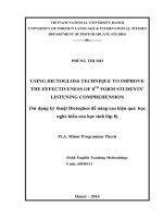
The dissertation was divided into six chapters. The organization of the
dissertation can be expressed as Figure 1-1.
Chapter 1 presents the motivation, objective, scopes of the research and
organization of the dissertation.
Chapter 2 shows a brief background of the research. In this chapter, an
overview of hard machining, cooling and lubrication in metal cutting, and
overview of minimum quantity lubrication were described.
Figure 1- 1 Research procedure
Chapter 3 presents research methods that were used in this study such as
Taguchi and response surface methodology.
Chapter 4 gives the optimization of MQL parameters. The Taguchi method
was utilized to design the experiment and find the optimal condition in MQL.
6
ANOVA is also used to perform an analysis of the influence of MQL parameters
on surface roughness.
Chapter 5 describes the outstanding effectiveness of MQL when compared
with dry cutting. In this chapter, a series of meticulous experiments related to the
hard-milling of AISI H13 steel were conducted under two different conditions
given as dry machining and MQL. Its result shows the influence of cutting
parameters on surface roughness and cutting force under both dry and MQLcutting conditions. Simultaneously, the result expresses the effectiveness of MQL
when compared with dry cutting.
The last section is chapter 6. This chapter show conclusion of the research
and recommendation for the future work.
7