GROUP 4 DISASSEMBLY AND ASSEMBLY
Bạn đang xem bản rút gọn của tài liệu. Xem và tải ngay bản đầy đủ của tài liệu tại đây (126.26 KB, 7 trang )
GROUP 4 DISASSEMBLY AND ASSEMBLY
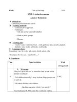
1. BRAKE PUMP
1) STRUCTURE
33
32
31
23
24
25
27
30
26
28
26
25
24
23
29
22
27
12
21
17
12
17
21
22
23
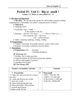
O-ring
O-ring
Splined coupling
Spacer plate
O-ring
24
25
26
27
28
Seal
Seal
Bushing
Bushing
Driven gear
4-31
29
30
31
32
33
Drive gear
Body
Cover
Spring washer
Bolt
2) GENERAL
(1) Introduction
Each unit comprises an end cover, body housing, the bush/gear assembly and a mounting flange
bolted together. The gear/bush assembly consists of a pair of meshing gears supported by plain
bearings in the bushes. The drive gear journal extends through the mounting flange to form the
drive shaft. A lip type shaft seal and O-rings provide external sealing whilst special lobe seals and
backing rings are used internally.
(2) Routine maintenance
No maintenance is necessary other than periodic checks for tightness of the mounting bolts and
visual examination for oil leakage. The unit should be kept externally clean, especially in the area
of the shaft seals as dirt can accelerate seal wear and cause leakage.
The unit must be operated only with clean oil and the system manufacturer's directions for
periodic renewal of system oil filter elements must be strictly observed.
(3) Field servicing
Seal kits and spare parts are available to enable units to be serviced.
4-32
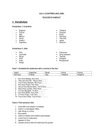
3) DISASSEMBLY
33
32
31
23
24
25
27
30
26
28
26
25
24
23
29
22
27
12
21
17
Ɠ Before disassembling ensure that the unit itself, bench and tools are thoroughly clean.
(1) Lightly mark the end cover(31), body(30) and spacer plate(22) to ensure reassembly in the
correct position.
(2) Remove the bolts(33) and separate the brake pump unit from the main pump using a soft faced
hammer.
(3) Remove splined coupling(21) and O-rings(12, 17) sealing the internal passages between the
pump sections.
(4) Remove the spacer plate(22) from the body(30), free from spacer plate using a soft faced
hammer.
(5) Remove the backup seal(24), the seal element(25) and the body O-ring(23).
(6) Remove the end cover(31) from the body(30).
(7) Remove the backup seal(24), the seal element(25) and the body O-ring(23).
Ɠ Before removing the internal components each bushing(26, 27) must be marked to denote its
location within the body. On the plain area of the bush away from the seal location, lightly mark.
(8) With the unit laying on its side grasp hold of the drive shaft(29) and pull it squarely out of the body
(30) bringing the bushing(26, 27) with it.
(9) Remove the driven gear(28) and the two remaining bushing(26, 27).
4-33
4) INSPECTION AND REPAIR
(1) Assessment
Each components should be thoroughly cleaned, carefully examined and assessed for suitability
re-use. Below is a guide for inspecting the various components.
(2) Body
ڸInspect the body bore cut-in where both gears wipe into the body.
ڹThe body can only be re-used if the cut-in is bright and polished in appearance and the depth
does not exceed 0.15mm(0.006").
ںThe body should be replaced if the surface is scored, has a matt appearance or shows signs that
the tip of the gears have dug in and torn away the surface material.
ڻThe body should be inspected to ensure that there is no superficial damage which may
adversely effect performance or sealing. Pay particular attention to the port threads and body Oring seal recesses.
(3) Spacer plate and end cover
ڸThe inner surfaces should be inspected to ensure that there is no unusual wear or scoring in the
regions where the body O-rings and backing rings contact, which result in external leakage.
ڹCheck the shaft seal recess for scoring or damage that could result in oil leakage around the
outer diameter of the shaft seal. Replacement shaft seals can be refitted with Loctite hydraulic
sealant to overcome slight damage in this area.
(4) Bushing
ڸThe side faces which abut the gears should be perfectly flat showing no sign of scoring.
Characteristically there are bright polished areas on this surface caused by loading against the
gear side faces, which is often more pronounced on the low pressure side. The bush should be
replaced if there is any general scoring or fine scoring with a matt appearance or tearing of the
surface material. Often there is a witness where the tips of the opposing gears have wiped an
overlap reassembling a half moon shape. There must be no noticeable wear step as it is critical
that the bush side face is completely flat to the gear side face.
ڹThe bearing liners are acceptable providing that they are not scored or show other damage.
The general outside area of the bush should not show any prominent signs of wear.
(5) Gears
ڸThe gear side faces should be examined for bruising or scoring. Often operation on
contaminated fluid shows scoring between the root of the gear and the journal undercut, which
leaves a wear step. If a wear step can be felt, coincidental with the root diameter, by drawing a
sharp pointed tool across the surface from the undercut outwards towards the tip of the gear,
then the gear is unserviceable.
ڹThe gear teeth should then be carefully examined to ensure that there are no signs of bruising or
pitting.
ںThe journal bearing surfaces should be completely free from scoring or bruising. The surface
should appear highly polished and smooth to touch.
ڻExamine the area where the shaft seal lips run on the drive shaft, this shows up as a polished
ring or rings. If a noticeable groove can be felt or there is scoring the shaft should be replaced.
ڼProvided the drive shaft is not damaged from the drive-coupling and the gears have not been
harmed as described above, then the gears can be re-used. If, however, the gears are
damaged they must be replaced as a matched pair.
ڽAs a matter of good practice, when pumps have been disassembled, all the seals should be
replaced. It is most important that only the genuine seals are used.
4-34
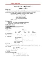
5) ASSEMBLY
33
32
31
23
24
25
27
30
26
28
26
25
24
23
29
22
27
12
21
17
Ɠ Ensure that all parts are perfectly clean and lightly lubricate the bushes and gears with hydraulic
oil(Ensure body O-ring recess and end faces remain free from oil). This will assist with their
assembly when they are later fitted into the body.
(1) Refit the cover drive shaft bushing(26) and cover driven bushing(27) into the undowelled end of
the body(30) from where they were removed.
(2) Place the end cover(31) against the body(30) and then stand the assembly on the cover so that
the hollow dowels are uppermost, i.e. the bushing should be at the bottom with the bushings
against the cover.
(3) Fit the drive shaft(29) and driven gear(28) back into their original positions in the body(30).
(4) Refit the separate plate drive shaft bushing(27) and the separate plate driven bushing(26) into
their original bores.
(5) Fit the new body O-ring(23).
(6) Fit the new seal element(25) and backup seal(24) to the bushing.
(7) Carefully refit the spacer plate(22) to the body(30). If the spacer plate(22) is not fitted squarely
the backup seal(24) may become misplaced and trapped, resulting in internal damage if the unit
is run in this condition.
4-35
ASSEMBLY
33
32
31
23
24
25
27
30
26
28
26
25
24
23
29
22
27
12
21
17
(8) Fit O-rings(12, 17) and coupling(21) to the spacer plate(22).
(9) Holding the whole unit together carefully turn it over, making sure it is supported on the spacer
plate(22) not the shaft.
(10) Slide off the end over and fit seals as in (5) and (6) above.
(11) Fit the end cover(31), taking care not to dislodge the backup seal(24) and bolt(33) the unit
together. Tighten the bolts to the torque figures stated below.
şTightening torque : 4.8Ź0.4kgfşm(35Ź3lbfşft)
Ɠ Pour a small amount of oil into a port and check that the shaft can be rotated without undue force
using a smooth jawed hand wrench hooked around the shaft or a suitable half coupling locked
against the key.
4-36
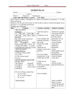
6) RUNNING-IN
Pressure gauge
Test unit
Microbic
filter
Variable
restrictor
Flow
meter
Relief valve
Strainer
Tank
(1) A unit which has been re-assembled with either new gears, bushes or body, must be carefully
run-in before it is subjected to full working conditions.
(2) Ideally this should be done on a test rig(See figure) where pressure can be gradually applied and
any wipings from the body cut-in arrested by filters.
(3) It is recommended that the unit is run-in at 1500rpm, initially, at zero pressure for one minute then
in stages with the pressure increased by 500psi every minute, until maximum rated pressure has
been attained. Frequently check the system temperature, ensuring that it does not exceed the
maximum permissible figure of 80Ɓ
C. If the temperature exceeds the system or unit specification
the test must be delayed and operated off-load until acceptable temperatures are obtained.
4-37