Controlled fabrication and assembly of carbon nanotubes based nanostructures
Bạn đang xem bản rút gọn của tài liệu. Xem và tải ngay bản đầy đủ của tài liệu tại đây (5.46 MB, 108 trang )
Controlled Fabrication and Assembly of
Carbon Nanotubes based Nanostructures
Wang Lei
(B.ENG. (1st Class Hons), NUS)
A THESIS SUBMITTED
FOR THE DEGREE OF MASTER OF ENGINEERING
DEPARTMENT OF ELECTRICAL AND COMPUTER ENGINEERING
NATIONAL UNIVERSITY OF SINGAPORE
2008
Abstract
Abstract
This project focuses on the controlled methods of fabrication and
assembly of carbon nanotube based nanostructures as future nanoscale
building blocks. Large scale (on 4-inch wafer) vertically aligned multi-walled
carbon nanotubes array on Ti electrodes with controlled position as
potential vertical interconnect or biosensing probe is fabricated by
plasma-enhanced chemical vapor deposition. Spin-on glass is found to be
good candidature for insulating layer coating on this structure. The total
resistance of the CNT-Ti electrode structure is measured to be 10 kΩ on
average. Individual carbon nanotube is also deposited on SiO2 surface with
controlled position and direction by modifying the SiO2 surface with APTS
patterned PMMA trench. The width of PMMA trench needs to be smaller
than 1 μm to have single CNT deposited. Carbon nanotubes are also
placed between electrodes with controlled position and direction by
dielectrophorectic force. Centrifugation of CNTs solution is found to be
effective to reduce the number of junk particles. With proper electrode
configuration and CNT solution concentration, individual CNT can be
precisely positioned between electrodes. Comparisons between electric
field simulation and experiment results show that CNTs are driven to the
higher field density region by dielectrophorectic force and aligned along the
electric field direction. By manipulating the electrodes geometry, electric
field could be modified in the intensity and direction. This paves the way for
using ac dielectrophoresis to align nanostructures in complex circuits.
i
Acknowledgements
Acknowledgements
The author would like to express his sincere gratitude to Assistant
Professor Wong Wai Kin and Associate Professor John Thong for all the
invaluable guidance, patience and the sunshiny encouragement which
made this project a great learning experience.
The author would like to thank the following staffs from CICFAR Lab for
their kind helps during the experiment process: Mrs. Ho Chiow Mooi, and
Mr. Koo Chee Keong.
The author also likes to thank the following graduate students from
CICFAR Lab for their kind help during the experiment process: Mr. Lim
Soon Huat and Mr. Yeong Kuan Song.
ii
Contents
Contents
Abstract
i
Acknowledgements
ii
List of Figures
vi
Chapter One – Introduction..................................................................... 1
1.1 General Characteristics of Carbon Nanotubes ............................ 2
1.2 Potential Application of Carbon Nanotubes ................................. 5
1.3 Motivation for the project ............................................................. 7
1.4 Objectives of the project .............................................................. 8
1.5 Scope of Thesis ........................................................................... 9
Chapter Two – Literature Review ......................................................... 10
2.1 Background................................................................................ 10
2.2 Growth of carbon nanotubes...................................................... 13
2.2.1 Arc-discharge.................................................................... 13
2.2.2 Laser Ablation ................................................................... 14
2.2.3 Chemical Vapor Deposition .............................................. 15
2.3 Positioning of carbon nanotubes................................................ 16
2.3.1 Field guided growth .......................................................... 16
2.3.2 Patterned deposition......................................................... 21
2.3.3 Dielectrophoresis .............................................................. 22
iii
Contents
Chapter Three – Fabrication of Carbon Nanotubes by CVD process 24
3.1 Objective .................................................................................... 24
3.2 Methodology .............................................................................. 25
3.2.1 Cleaning procedure of test die .......................................... 26
3.2.2 Catalyst Coating ............................................................... 26
3.2.3 Catalyst annealing ............................................................ 28
3.2.4 Chemical Vapor Deposition............................................... 30
3.3 Experiment and Results ............................................................. 34
3.3.1 Thermal chemical vapor deposition .................................. 34
3.3.2 Plasma-enhanced chemical vapor deposition .................. 35
3.4 Summary ................................................................................... 41
Chapter
Four
–
Fabrication
of
Carbon
Nanotubes
based
Microelectrode Array ............................................................................. 43
4.1 Objective .................................................................................... 43
4.2 Experiment and Results ............................................................. 44
4.2.1 Metal layer patterning ....................................................... 46
4.2.2 Catalyst patterning ............................................................ 49
4.2.3 Carbon nanotube growth .................................................. 50
4.2.4 Insulating layer coating ..................................................... 55
4.3 Summary ................................................................................... 58
Chapter Five -- Positioning of Carbon Nanotubes by Patterned
Deposition .............................................................................................. 60
5.1 Objective .................................................................................... 60
iv
Contents
5.2 Experiment and results .............................................................. 60
5.3 Summary ................................................................................... 66
Chapter Six – Controlled Positioning of Carbon Nanotubes by ac
Dielectrophoresis................................................................................... 68
6.1 Objective .................................................................................... 68
6.2 Methodology .............................................................................. 69
6.3 Experiment and results .............................................................. 71
6.3.1 CNT suspension preparation ............................................ 71
6.3.2 The effect of the concentration of CNT suspension on
dielectrophoresis ....................................................................... 73
6.3.3 Dielectrophoresis on two-electrode structure.................... 79
6.3.4 Dielectrophoresis on four-electrode geometry .................. 83
6.4 Summary ................................................................................... 87
Chapter Seven – Conclusions .............................................................. 89
References.............................................................................................. 92
v
List of Figures
List of Figures
Figure 1.1 Density of electronic states N(E) as a function of the
dimensionality of the structure
2
Figure 1.2 Single-walled and Multi-walled Carbon Nanotubes
3
Figure 1.3 Schematic diagram showing how a hexagonal sheet of
graphite is ‘rolled’ to form a carbon nanotube
3
Figure 1.4 Different types of SWCNT (a) Zigzag SWCNT (b)
Armchair SWCNT
4
Figure1.5 Model of Infineon’s 18nm nanotube transistor
6
Figure 2.1 Top down and Bottom up approach
11
Figure 2.2 Model of Infineon’s vertical carbon nanotube transistor
12
Figure 2.3 Diagram illustration of the arc-discharge technique
13
Figure 2.4 Schematic illustration of the laser vaporization technique
14
Figure 2.5 SEM images showing electric field directed SWCNTs
growth
16
Figure 2.6 Schematic representation of the PECVD process for
growing vertically aligned carbon nanotubes
18
Figure 2.7(a) shows MWCNFs at a bias voltage of −550V (360W,
670 mA)) (b) Increasing the bias to −600V (470W, 780 mA) gives
exclusive growth of MWCNTs.
19
Figure 2.8 Growth of nanotubes on lithographically defined areas
20
vi
List of Figures
Figure 2.9 AFM images of carbon nanotubes deposited on patterned
21
PMMA trench
Figure 2.10 SEM micrographs showing carbon nanotubes
dielectrophoretically aligned along adjacent electrodes
22
Figure 2.11 A thin film formed by DEP from a suspension of
individually dispersed SWNCTs.
23
Figure 3.1 Procedures for Growth of Carbon Nanotubes
25
Figure 3.2 Catalyst coating process using Evaporator
27
Figure 3.3 Thermal Evaporator
28
Figure 3.4 Conditions on the surface energies of substrate
29
Figure 3.5 Tip-growth and Base growth of Carbon nanotubes
30
Figure 3.6 Schematic of Chemical Vapor Deposition System
31
Figure 3.7 Carbon nanotube Alignment mechanism during PECVD
as proposed by Merkulov
32
Figure 3.8 Multi-walled carbon nanotubes grown by thermal CVD
33
Figure 3.9 TEM images of carbon nanotubes grown by thermal CVD
process
34
Figure 3.10 SEM image shows carbon nanotubes grown by PECVD
on SiO2
35
Figure 3.11 30 degree tilted SEM image shows carbon nanotubes
36
Figure 3.12 SEM image of carbon nanotube grown by PECVD on Ti
surface
37
Figure 3.13 SEM image of vertically-aligned MWCNT grown on Si3N4
membrane
38
vii
List of Figures
Figure 4.1 Schematic diagram of the fabrication process of carbon
nanotube based microelectrodes array
42
Figure 4.2 Process problems with insulating layer coated wafer
43
Figure 4.3 Mask design for the metal layer
45
Figure 4.4 Spinner for resist coating
45
Figure 4.5 Optical pictures of Ti electrodes
46
Figure 4.6 Optical image showing the catalyst pattern by
Photolithography
47
Figure 4.7 CVD growth result of carbon nanotube on 4-inch wafer at
730oC
49
Figure 4.8 CVD growth result of carbon nanotube on 4-inch wafer
with a lower plasma power
50
Figure 4.9 CVD growth result of carbon nanotube on 4-inch wafer
with a lower flow rate of C2H2
51
Figure 4.10 Tilted SEM images showing patterned carbon nanotubes
grown on Ti line
52
Figure 4.11 Photo of 4-inch wafer with carbon nanotubes-titanium
electrodes array
53
Figure 4.12 SEM image of Carbon nanotube-titanium electrodes
testing wafer after SiO2 coating
54
Figure 4.13 SiO2 coating on carbon nanotube by evaporation
55
Figure 5.1 Schematic of Carbon nanotubes being deposited on SiO2
surface by patterned PMMA trench
58
Figure 5.2 Testing patterns for PMMA trenches
60
viii
List of Figures
Figure 5.3 SEM image shows single carbon nanotube deposited in
predefined location by monolayer assembly in 0.5 μm PMMA trench
60
Figure 5.4 SEM image shows no carbon nanotube could be found in
2 μm PMMA trench
61
Figure 5.5 SEM image shows no carbon nanotube could be found
the PMMA trenches larger than 2 μm
62
Figure 5.6 SEM image of the carbon nanotube positioned in 1 μm
PMMA trench
62
Figure 5.7 SEM image showing that carbon nanotubes positioned in
tandem along the PMMA trench
63
Figure 6.1 Schematic of the experiment set up for dielectrophoresis
66
Figure 6.2 Arc discharge carbon nanotube powder produced by SES
Research
68
Figure 6.3 Ultrasonic machine
69
Figure 6.4 Weighing machine for CNT powder measurement
70
Figure 6.5 Round-shape electrode structure for carbon nanotube
dielectrophoresis.
71
Figure 6.6 Carbon nanotube-DCE suspension with different
concentration
72
Figure 6.7 SEM image of dielectrophoresis result with different CNT
solution concentration
73
Figure 6.8 Simulation of the electric field intensity and direction for
the round-shape electrode structure
77
ix
List of Figures
Figure
6.9
Two
electrodes
structure
for
carbon
nanotube
dielectrophoresis
78
Figure 6.10 Simulation of the electric field intensity for the
two-electrode geometry
79
Figure 6.11 Centrifuge machine Hettich Mikro120
79
Figure 6.12 SEM image of dielectrophoresis on the two electrodes
structure, ac power supply: square wave 5 Vpp, 100 kHz
80
Figure 6.13 SEM image of dielectrophoresis on the two electrodes
structure, ac power supply: square wave 1 Vpp, 100 kHz
81
Figure 6.14 Four electrodes structure for carbon nanotube
dielectrophoresis.
83
Figure 6.15 Simulation of the electric field intensity for the
four-electrode geometry
84
Figure 6.16 SEM image showing a single carbon nanotube aligned
between two electrodes in four-electrode geometry
85
Figure 6.17 I-V characteristic of the carbon nanotube between two
electrodes
86
x
Chapter 1 -- Introduction
Chapter One – Introduction
For
nanostructured
materials
(e.g.
nanotubes,
nanowires
and
nanoparticles), the presence of small volumes, free surfaces and strong
bonding can dramatically alter mechanical and electrical behavior.
Because of unique bonding configurations and quantum mechanical size
effects, coupling between mechanical and electronic properties can be
observed in many of these systems.
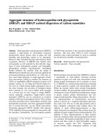
Figure 1.1 shows the density of electron states as the dimensionality of
the structure decreases. Electron transport property of a nanostructure is
very different from the bulk material. For example, in the case of one
dimension material, carbon nanotube (CNT), at low temperature, charge
transport in CNT is ballistic in the micrometer range if no defects are
present due to the translational symmetry of the tube along the axis. The
resistance of the tube is virtually independent of the length at the scale of
interest. The absence of scattering along the tube allows current densities
of more than 1000 times that in polycrystalline metals [1, 2]. The electron
transport properties of the carbon nanotube connected to metallic
electrodes depends on the carbon nanotube-metal junction, and may
change with increasing transparencies of the junctions: from the Coulomb
blockade regime, through the Kondo effect, and Fabry-Perot resonator-like
behavior up to the Fano resonance.[3]
1
Chapter 1 -- Introduction
Figure 1.1 Density of electronic states N(E) as a function of the
dimensionality of the structure.
1.1 General Characteristics of Carbon Nanotubes
Carbon nanotubes were discovered by Sumio lijima in 1991. Since then,
they have been of great interest among the scientific community as well as
the engineering community, both from a fundamental science point of view
and for future applications. Their large length (up to several microns) and
small diameter (several nanometers) result in a large aspect ratio.
Therefore, carbon nanotubes are expected to possess extraordinary
electrical, mechanical and chemical properties.
2
Chapter 1 -- Introduction
Figure1.2 Single-walled and Multi-walled Carbon Nanotubes
There are two types of carbon nanotubes: single-walled nanotubes
(SWCNTs) and multi-walled nanotubes (MWCNTs), which are shown in
Figure 1.2. Single-walled nanotubes have a diameter of close to 1
nanometer, with a tube length that can be many thousands of times longer.
The structure of a SWCNT can be imagined by wrapping a one-atom-thick
layer of graphite, called graphene, into a seamless cylinder. The way the
graphene sheet is wrapped is represented by a pair of indices (n,m) called
the chiral vector (figure 1.3).
Figure 1.3 Schematic diagram showing how a hexagonal sheet of graphite
is ‘rolled’ to form a carbon nanotube
3
Chapter 1 -- Introduction
The integers n and m denote the number of unit vectors along two
directions in the honeycomb crystal lattice of graphene. If m=0, the
nanotubes are called "zigzag" (figure 1.4 (a)). If n=m, the nanotubes are
called "armchair" (figure 1.4 (b)).
Figure1.4 Different types of SWCNT (a) Zigzag SWCNT (b) Armchair
SWCNT
Because of the symmetry and unique electronic structure of graphene,
the structure of a nanotube strongly affects its electrical properties. For a
(n,m) nanotube, if n−m is a multiple of 3, the nanotube is metallic,
otherwise the nanotube is semiconducting. So all armchair (n=m)
nanotubes are metallic [4].
MWCNTs have more than one shell with increasing diameters from
innermost shell to the outmost shell. The diameter of the outmost shell
typically ranges from 10 nm to 100 nm.
4
Chapter 1 -- Introduction
Carbon
nanotubes
are
also
exceedingly
strong
mechanically,
chemically and thermally very stable and have excellent thermal
conductivity. These unique properties of carbon nanotubes make them the
object of extensive studies in both basic science and technology. A great
challenge for nanotubes is the ability for controlled fabrication of
semiconducting or metallic CNTs, as well as the difficulties in manipulating
individual carbon nanotube in a controlled way.
1.2 Potential Application of Carbon Nanotubes
Carbon nanotubes have attracted much attention around the world with
their unique properties, which may lead to lots of promising applications.
Potential practical applications have been reported such as electronic
devices [5], nanoelectronic devices [6], high sensitivity nanobalance for
nanoscopic particles [5], supercapacitors [7], field emission materials [8],
nanotweezers [9], hydrogen storage [10] and chemical sensors [11]. New
applications are likely in the diamond industry since experiments have
shown the conversion of carbon nanotubes to diamond under high
pressure and high temperatures with the presence of a certain catalyst [12].
Carbon nanotube is also a candidate to use as interconnects or FET
channels in electronics devices when the current silicon technology
reaches its fundamental size limit [13]. Figure 1.5 shows a model of
Infineon’s 18nm nanotube transistor [14]. These are just a few possibilities
5
Chapter 1 -- Introduction
that are currently being explored. As more research and development are
conducted, the potential applications of CNTs will continue to increase.
.
Figure1.5 Model of Infineon’s 18nm nanotube transistor[14]
6
Chapter 1 -- Introduction
1.3 Motivation for the project
As shown in the previous section, carbon nanotubes indeed have many
fascinating properties as nanoscale building blocks. However, their use in
practical devices still has great challenges. One critical challenge is to
develop a technology that enables precise placement of individual carbon
nanotube on the substrate. For practical applications, carbon nanotube
must be positioned on exact substrate locations, so it could be electrically
addressed and connected to the macroscopic outside world. The lack of a
solution for the controlled deposition of carbon nanotubes at given
locations on the wafer is a major bottleneck. Although a great deal of work
has been carried out to look for a possible solution, how to place the
nanotubes at desired locations with targeted shapes, directions, and
densities for fabricating functional devices are still unsolved problems. As
silicon devices approach fundamental scaling limits, methods are urgently
needed to assemble carbon nanotubes over large-scale areas with
controllable morphology, location, orientation, and density. All these
promising properties of carbon nanotubes, potential applications and the
difficulties in the controlled fabrication and assembly motivate the author to
explore large-scale fabrication of carbon nanotube based structures with
controlled parameters and assembly of carbon nanotubes with single tube
precision in this project.
7
Chapter 1 -- Introduction
1.4 Objectives of the project
Methods of controlled fabrication and assembly of carbon nanotube
based structures such as interconnects, probes and FET channels will be
explored. Wafers with large-scale vertically-aligned CNT array in contact
with metal electrodes will be fabricated with controlled tube position. Single
CNT is going to be placed horizontally on the wafer surface with controlled
position by patterned deposition. Individual carbon nanotube is going to be
positioned between electrodes by dielectrophoresis with controlled position.
There are three main objectives in this project:
z
To fabricate large-scale vertically aligned carbon nanotubes array on
metal electrodes with controlled position and test the basic electrical
property of the structure.
z
To control the positioning of carbon nanotube in a horizontal direction
on a wafer surface by patterned deposition. Based on the experiment
results, to suggest the optimum patterning parameters for depositing
single nanotube with controlled position.
z
To control the positioning of carbon nanotube between metal
electrodes with single tube precision by dielectrophoresis and analyze
correlation between carbon nanotube positioning and electric field
intensity.
8
Chapter 1 -- Introduction
1.5 Scope of Thesis
This thesis is divided into 7 chapters. Chapter 2 presents a literature
review of the topic of carbon nanotube properties, fabrication and methods
to achieve controlled positioning. Chapter 3 focuses on the fabrication of
carbon nanotubes using chemical vapor deposition (CVD) process.
Aspects of experiment process and the parameters studied will be
discussed. Chapter 4 shows the fabrication process of large-scale carbon
nanotube based microelectrode-array structure, which has potential
applications as probes, interconnects, vertical channels and so on. Basic
electrical property of the structure will be shown. Chapter 5 explores the
precise carbon nanotube deposition on silicon dioxide by chemically
modifying the wafer surface. Chapter 6 focuses on the positioning of
carbon nanotube between electrodes by dielectrophoresis. The effects of
process parameters such as concentration of carbon nanotube suspension,
electric field intensity and direction will be discussed. The method of
precisely positioning a single tube between electrodes will be presented.
Basic electrical property of single carbon nanotube will be shown. Lastly,
the report will be concluded in Chapter 7.
9
Chapter 2 – Literature Review
Chapter Two – Literature Review
2.1 Background
In 1959, Professor Richard Feynman gave a seminal talk at the annual
meeting of the American Physical Society at the California Institute of
Technology, in which he first envisioned the impact of things at ultra-small
scale on future science and technology. The topics that have been covered
by his talk include but are not limited to data storage, electron microscope,
biology, small machine, manipulation of atoms and so on. Great progress
has been made after 1959. Nanostructures became a broad and
interdisciplinary area of research and development activity.
It has the
potential for revolutionizing the ways in which materials and products are
created and the range and nature of functionalities that can be accessed.
Silicon-based microelectronic devices have revolutionized the world in
the past three decades. Integrated circuits, built up from many silicon
devices (such as transistors and diodes) on a single chip, control
everything from cars to cell phones, not to mention the Internet. The desire
for cheaper electronic memory, and faster processors, is still not satisfied.
Every year, more powerful chips with smaller device size are introduced.
The miniaturization of the devices found in integrated circuits is predicted
10
Chapter 2 – Literature Review
by the semiconductor industry roadmap to reach atomic dimensions in
2012. According to Muller, silicon devices will then reach their fundamental
physical limit. [15]
Figure 2.1 Top down and Bottom up approach
As the top-down approach is reaching its limit, researchers are
intensively developing the bottom-up processes. Various kinds of
nanoparticles [16], nanowires [17] and nanotubes are used as building
blocks for next generation electronic devices. There has been intense effort
to develop carbon nanotubes for electron transport in the next generation
of devices. The small diameter of single-walled carbon nanotubes
(SWCNTs), along with their long length, low scattering, and almost ballistic
transport, makes them very attractive as potential channels in field effect
transistors (FETs). Figure 2.2 shows the model of Infineon’s vertical carbon
nanotube transistor [18]. Great effort has been expended to integrate these
11
Chapter 2 – Literature Review
FETs into logic gates and logic circuits [19].
Figure 2.2 Model of Infineon’s vertical carbon nanotube transistor [18]
Great challenges still need to be overcome for nanotubes to be viable
as channels and interconnects in FETs. Among these, the precise
positioning of nanotubes in devices needs to be addressed.
Several methods have been proposed to achieve controlled positioning
of carbon nanotubes, including chemical modification of the substrate [20],
growing nanotubes on a substrate directly by chemical vapor deposition
[21], the mechanical transfer protocol [22], and the use of dielectrophoresis
to position carbon nanotubes in electrode gaps [23-25]. All the methods
could be divided into two groups: positioning by direct growth and
post-synthesis positioning.
12
Chapter 2 – Literature Review
2.2 Growth of carbon nanotubes
The techniques for production of carbon nanotubes can be roughly
divided into three main classes: Arc-discharge, Laser ablation and
Chemical vapor deposition.
2.2.1 Arc-discharge
In the arc-discharge technique (figure 2.3), an electric arc is generated
between two graphite electrodes under a helium or argon atmosphere,
which causes the graphite to vaporize and condense on the cathode. The
deposit contains the nanotubes and also fullerenes, amorphous carbon
materials and catalyst particles. This technique requires further purification
to separate the CNTs from the by-products. The electrodes of graphite are
doped with catalytic metal atoms (Ni, Co) for the production of SWCNTs.
Figure 2.3 Diagram illustration of the arc-discharge technique (Thostenson
et al 2001).
13
Chapter 2 – Literature Review
2.2.2 Laser Ablation
The laser ablation method is the second technique for producing carbon
nanotubes (figure 2.4). This process is known to produce CNTs with the
highest quality and high purity of single walls [26]. In this process, a piece
of graphite is vaporized by laser irradiation under an inert atmosphere. With
every laser pulse, a plume of carbon and metal vapors emanates from the
surface of the target, and CNTs start to grow in the gas phase. This results
in soot containing nanotubes. They are then collected on a water-cooled
target. Two kinds of products are possible: multi-walled carbon nanotubes
or single-walled carbon nanotubes. The graphite target is doped with cobalt
and nickel catalyst to produce single-walled nanotubes [27]. For this
process, a purification step by gasification is also needed to eliminate
carbonaceous material.
Figure 2.4 Schematic illustration of the laser vaporization technique (Guo
et al 1995).
14