2 basics wind
Bạn đang xem bản rút gọn của tài liệu. Xem và tải ngay bản đầy đủ của tài liệu tại đây (3.42 MB, 64 trang )
Power Systems & Energy Course:
Wind Generation Basics
Jason MacDowell
Atmospheric Circulation
Uneven heating of the earth
by the sun drives global
atmospheric circulation
Source: />
Earth’s rotation causes large
E-W component of wind via
Coriolis effect
© 2016 General Electric International, Inc. All rights reserved. Not for distribution without permission.
2-2 /
Cyclonic Flow
L
H
• Flow from high pressure system to low pressure system causes
rotation of air due to Coriolis effect
• Rotation is clockwise along isobars around high pressure system
counterclockwise around low pressure system (storm)
• Wind velocity greatest where isobars are more closely spaced
(greater pressure gradient)
© 2016 General Electric International, Inc. All rights reserved. Not for distribution without permission.
2-3 /
Weather Systems
At any given time, the
earth has numerous
high and low pressure
weather systems
© 2016 General Electric International, Inc. All rights reserved. Not for distribution without permission.
2-4 /
Local Atmospheric Circulation
Source: />
Localized atmospheric heating also drives wind
© 2016 General Electric International, Inc. All rights reserved. Not for distribution without permission.
2-5 /
Vertical Wind Shear
Atmospheric boundary layer is the
layer affected by surface friction
Friction with the earth’s surface
causes vertical wind shear
• Increasing velocity with height
• Change in direction
Above boundary layer, wind flow is
geostrophic, and non-turbulent
Inside boundary layer:
• General wind direction shifted more
toward pressure gradient
• Turbulent flow, “mixes” wind to the
surface
Wind velocity
and direction
Boundary level is thinner:
• Over water, and smoother ground
• At night, due to decreased convection
Wind speed at hub height (~80m) can
be far greater than at ground level
© 2016 General Electric International, Inc. All rights reserved. Not for distribution without permission.
2-6 /
Orographic Effects
Mountain passes funnel wind
Mountain wind shadows block wind
Ridges enhance wind velocity
Mountain waves can enhance velocity
Source: />
© 2016 General Electric International, Inc. All rights reserved. Not for distribution without permission.
2-7 /
Wind Resources in the US
© 2016 General Electric International, Inc. All rights reserved. Not for distribution without permission.
2-8 /
Wind Classification
Germanischer Lloyd, Certification Agency, and International Electrotechnical
Commission (IEC) Standards detail specific loading conditions that need to be
evaluated:
IEC Wind
Class
V Average
I
II
III
IV
S
10
8.5
7.5
6
70.0
59.5
52.5
42
Specified
by
Designer
(m/s)
V 50 yr Extreme
(m/s)
Turbulence models, deterministic gusts, sudden directional changes, ice loading,
atmospheric density, wind shear, wind upflow angle etc…
© 2016 General Electric International, Inc. All rights reserved. Not for distribution without permission.
2-9 /
0
_Finding
Wind
© 2016 General Electric International, Inc. All rights reserved. Not for distribution without permission.
2-10 /
Siting
High-Resolution Wind Maps
A
Potential
Development Sites
© 2016 General Electric International, Inc. All rights reserved. Not for distribution without permission.
2-11 /
Measuring the wind
Met Mast
ENRON WIND - Met Mast Configuration
50m mast system
0.5 m
ENRON WND - Met Mast Details
Mast & Boom Orientation
0.5 m
1.5 m
2.0m (1.5m)
N
2.0m (1.5m)
0.5 m
120°
0.5 m
150°
°
90
2.0m (1.5m)
2.0m (1.5m)
[Values in brackets = minimum]
°
90
0.5 m
0.5 m
2.0m (1.5m)
2.0m (1.5m)
h5
h4
[Values in brackets = minimum]
Requirement for booms > 1.5m
0.5 m
…
0.5 m
1.5 m
2.0m (1.5m)
2.0m (1.5m)
2.0m (1.5m)
2.0m (1.5m)
0.5 m
h3
2/3
1/3
0.5 m
30°
h2
[Values in brackets = minimum]
h1
Heights of sensors
h 1 = Wind vanes @ 23,5m
h 2 = Anemometers @ 25m
h 3 = anemometers @ 37.5m
h 4 = wind vanes / temperature probe @ 48,5m
h 5 = anemometers @ 50m
© 2016 General Electric International, Inc. All rights reserved. Not for distribution without permission.
2-12 /
Instrumentation
Wind Vane
Temperature
Probe
Anemometer
Barometric
Probe
Data Logger: 1 Hz sample rate
10 minute averaging interval
© 2016 General Electric International, Inc. All rights reserved. Not for distribution without permission.
2-13 /
Analyzing the wind
Statistical methods
a
h2
v 2 = v1
h1
( 1 2)
a = ln v v
ln(h1 h2 )
Further formulas for calculation of wind
characteristics:
(Empiric formulas according IEC standards)
(1)
(2)
Vref = 5 x Vm
(3)
Ve1 = 0.75 x Ve50
(4)
Ve50 = 1.4 x Vref
(5)
© 2016 General Electric International, Inc. All rights reserved. Not for distribution without permission.
2-14 /
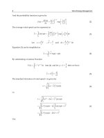
Site Suitability
Rule of Thumb Measures
Assess slopes – greater than 20% within 100m - ????
Wake losses for individual WTG higher than 8% - ????
Overall average wake loss higher than 5% - ????
Separation distances less than 2.5 rotor diameters - ?????
© 2016 General Electric International, Inc. All rights reserved. Not for distribution without permission.
2-15 /
Wind Turbines
© 2016 General Electric International, Inc. All rights reserved. Not for distribution without permission.
2-16 /
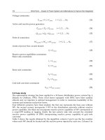
Wind Turbines as a Power Source
Power Sources
Overhead Transmission
Distribution Substation
Distribution Lines
Commercial
Load
Industrial
Load
Residential
Load
© 2016 General Electric International, Inc. All rights reserved. Not for distribution without permission.
2-17 /
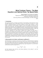
Wind Turbine Components
GE 1.5 MW
1200-1700 Households
Rotor
35 metric tons
77 meters diameter
Nacelle
52 metric tons
Tower
120+ metric tons
60 to 100 meters
Image source:
hokiesports.com
Automobile
(for scale)
Image source:
GE Energy
© 2016 General Electric International, Inc. All rights reserved. Not for distribution without permission.
2-18 /
Wind Turbine Components
Generator
Gear Box
Blades
Nacelle
Rotor
Hub
Main
Shaft
Tower
© 2016 General Electric International, Inc. All rights reserved. Not for distribution without permission.
2-19 /
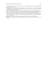
Modern Wind Turbines
Electrical Pitch
Drives
GE 1.6 xle
• 1.6 MW
• 82.5 M Rotor Diameter
• 100 M Tower
Doubly-Fed
Generator
• 98% Availability
• Speed 10-20 RPM
Main Shaft &
Bearing
• Variable Pitch
Gearbox
Epoxy-Glass
Composite Blades
GE 1.5 Series WTG
52 metric ton nacelle
35 metric ton rotor
Transformer &
Electrical
Power Electronic
Converter
© 2016 General Electric International, Inc. All rights reserved. Not for distribution without permission.
2-20 /
© 2016 General Electric International, Inc. All rights reserved. Not for distribution without permission.
2-21 /
Fundamentals of Wind Turbines
© 2016 General Electric International, Inc. All rights reserved. Not for distribution without permission.
2-22 /
Wind Turbine Basics
Converting one form of energy to another
Kinetic
Energy
Mechanical
Energy
Rotor
45 - 52%
Gearbox
95 – 97%
Electrical
Energy
Generator +
Power Converter
90 – 95%
42 – 50% Efficient Today… Theoretical Maximum is 59% (no losses)
© 2016 General Electric International, Inc. All rights reserved. Not for distribution without permission.
2-23 /
Aerodynamic Lift – Bernoulli Effect
Bernoulli’s principle:
Increased speed of fluid
flow results in a decrease
of pressure
Fast air
movement
Slow air movement
Resulting
air power
Incoming
air
Vacuum
Angle of incidence
Positive
pressure
Horizontal
The air moves faster above the rotor blade than under it. This creates lift.
All modern WTGSs are lift machines
© 2016 General Electric International, Inc. All rights reserved. Not for distribution without permission.
“WindInternational,
Energy Handbook”,
et.al.;
ISBN: 0471489972;
edition (November
15, 2001)
© 2016 General Electric
Inc.Tony
AllBurton
rights
reserved.
Not for 1st
distribution
without
permission.
2-24 /
Aerodynamic Forces on Wind Turbine Blade
Wind
Rotational Speed
Equation for Lift (L)
r = air density
v =airspeed
A = airfoil area
CL = coefficient of lift
Angle of Attack
Axial Thrust
Circumferential
Component
Parasitic Drag
© 2016 General Electric International, Inc. All rights reserved. Not for distribution without permission.
2-25 /