tài liệu tiếng anh chuyên ngành điệnđiện tử ieee std 1364 2001
Bạn đang xem bản rút gọn của tài liệu. Xem và tải ngay bản đầy đủ của tài liệu tại đây (2.79 MB, 791 trang )
IEEE Std 1364-2001
IEEE Standards
(Revision of
IEEE Std 1364-1995)
®
IEEE Standard Verilog Hardware
Description Language
IEEE Computer Society
Sponsored by the
Design Automation Standards Committee
Published by
The Institute of Electrical and Electronics Engineers, Inc.
3 Park Avenue, New York, NY 10016-5997, USA
28 September 2001
Print: SH94921
PDF: SS94921
IEEE Std 1364-2001
(Revision of
IEEE Std 1364-1995)
IEEE Standard Verilog® Hardware
Description Language
Sponsor
Design Automation Standards Committee
of the
IEEE Computer Society
Approved 17 March 2001
IEEE-SA Standards Board
Abstract: The Verilog¤ Hardware Description Language (HDL) is defined in this standard. Verilog
HDL is a formal notation intended for use in all phases of the creation of electronic systems. Because it is both machine readable and human readable, it supports the development, verification,
synthesis, and testing of hardware designs; the communication of hardware design data; and the
maintenance, modification, and procurement of hardware. The primary audiences for this standard
are the implementors of tools supporting the language and advanced users of the language.
Keywords: computer, computer languages, digital systems, electronic systems, hardware, hardware description languages, hardware design, HDL, PLI, programming language interface, Verilog
HDL, Verilog PLI, Verilog¤
The Institute of Electrical and Electronics Engineers, Inc.
3 Park Avenue, New York, NY 10016-5997, USA
Copyright © 2001 by the Institute of Electrical and Electronics Engineers, Inc.
All rights reserved. Published 28 September 2001. Printed in the United States of America.
Print:
PDF:
ISBN 0-7381-2826-0
ISBN 0-7381-2827-9
SH94921
SS94921
No part of this publication may be reproduced in any form, in an electronic retrieval system or otherwise, without the prior
written permission of the publisher.
IEEE Standards documents are developed within the IEEE Societies and the Standards Coordinating Committees of the
IEEE Standards Association (IEEE-SA) Standards Board. The IEEE develops its standards through a consensus development process, approved by the American National Standards Institute, which brings together volunteers representing varied
viewpoints and interests to achieve the final product. Volunteers are not necessarily members of the Institute and serve without compensation. While the IEEE administers the process and establishes rules to promote fairness in the consensus development process, the IEEE does not independently evaluate, test, or verify the accuracy of any of the information contained
in its standards.
Use of an IEEE Standard is wholly voluntary. The IEEE disclaims liability for any personal injury, property or other damage, of any nature whatsoever, whether special, indirect, consequential, or compensatory, directly or indirectly resulting
from the publication, use of, or reliance upon this, or any other IEEE Standard document.
The IEEE does not warrant or represent the accuracy or content of the material contained herein, and expressly disclaims
any express or implied warranty, including any implied warranty of merchantability or fitness for a specific purpose, or that
the use of the material contained herein is free from patent infringement. IEEE Standards documents are supplied “AS IS.”
The existence of an IEEE Standard does not imply that there are no other ways to produce, test, measure, purchase, market,
or provide other goods and services related to the scope of the IEEE Standard. Furthermore, the viewpoint expressed at the
time a standard is approved and issued is subject to change brought about through developments in the state of the art and
comments received from users of the standard. Every IEEE Standard is subjected to review at least every five years for revision or reaffirmation. When a document is more than five years old and has not been reaffirmed, it is reasonable to conclude
that its contents, although still of some value, do not wholly reflect the present state of the art. Users are cautioned to check
to determine that they have the latest edition of any IEEE Standard.
In publishing and making this document available, the IEEE is not suggesting or rendering professional or other services
for, or on behalf of, any person or entity. Nor is the IEEE undertaking to perform any duty owed by any other person or
entity to another. Any person utilizing this, and any other IEEE Standards document, should rely upon the advice of a competent professional in determining the exercise of reasonable care in any given circumstances.
Interpretations: Occasionally questions may arise regarding the meaning of portions of standards as they relate to specific
applications. When the need for interpretations is brought to the attention of IEEE, the Institute will initiate action to prepare
appropriate responses. Since IEEE Standards represent a consensus of concerned interests, it is important to ensure that any
interpretation has also received the concurrence of a balance of interests. For this reason, IEEE and the members of its societies and Standards Coordinating Committees are not able to provide an instant response to interpretation requests except in
those cases where the matter has previously received formal consideration.
Comments for revision of IEEE Standards are welcome from any interested party, regardless of membership affiliation with
IEEE. Suggestions for changes in documents should be in the form of a proposed change of text, together with appropriate
supporting comments. Comments on standards and requests for interpretations should be addressed to:
Secretary, IEEE-SA Standards Board
445 Hoes Lane
P.O. Box 1331
Piscataway, NJ 08855-1331
USA
Note: Attention is called to the possibility that implementation of this standard may require use of subject matter covered by patent rights. By publication of this standard, no position is taken with respect to the existence or
validity of any patent rights in connection therewith. The IEEE shall not be responsible for identifying patents
for which a license may be required by an IEEE standard or for conducting inquiries into the legal validity or
scope of those patents that are brought to its attention.
The IEEE and its designees are the sole entities that may authorize the use of IEEE-owned certification marks and/or trademarks to indicate compliance with the materials set forth herein.
Authorization to photocopy portions of any individual standard for internal or personal use is granted by the Institute of
Electrical and Electronics Engineers, Inc., provided that the appropriate fee is paid to Copyright Clearance Center. To
arrange for payment of licensing fee, please contact Copyright Clearance Center, Customer Service, 222 Rosewood Drive,
Danvers, MA 01923 USA; (978) 750-8400. Permission to photocopy portions of any individual standard for educational
classroom use can also be obtained through the Copyright Clearance Center.
Introduction
(This introduction is not part of IEEE Std 1364-2001, IEEE Standard Verilog® Hardware Description Language.)
The Verilog¤ Hardware Description Language (Verilog HDL) became an IEEE standard in 1995 as IEEE
Std 1364-1995. It was designed to be simple, intuitive, and effective at multiple levels of abstraction in a
standard textual format for a variety of design tools, including verification simulation, timing analysis, test
analysis, and synthesis. It is because of these rich features that Verilog has been accepted to be the language
of choice by an overwhelming number of IC designers.
Verilog contains a rich set of built-in primitives, including logic gates, user-definable primitives, switches,
and wired logic. It also has device pin-to-pin delays and timing checks. The mixing of abstract levels is
essentially provided by the semantics of two data types: nets and variables. Continuous assignments, in
which expressions of both variables and nets can continuously drive values onto nets, provide the basic
structural construct. Procedural assignments, in which the results of calculations involving variable and net
values can be stored into variables, provide the basic behavioral construct. A design consists of a set of modules, each of which has an I/O interface, and a description of its function, which can be structural, behavioral, or a mix. These modules are formed into a hierarchy and are interconnected with nets.
The Verilog language is extensible via the Programming Language Interface (PLI) and the Verilog Procedural Interface (VPI) routines. The PLI/VPI is a collection of routines that allows foreign functions to access
information contained in a Verilog HDL description of the design and facilitates dynamic interaction with
simulation. Applications of PLI/VPI include connecting to a Verilog HDL simulator with other simulation
and CAD systems, customized debugging tasks, delay calculators, and annotators.
The language that influenced Verilog HDL the most was HILO-2, which was developed at Brunel University in England under a contract to produce a test generation system for the British Ministry of Defense.
HILO-2 successfully combined the gate and register transfer levels of abstraction and supported verification
simulation, timing analysis, fault simulation, and test generation.
In 1990, Cadence Design Systems placed the Verilog HDL into the public domain and the independent Open
Verilog International (OVI) was formed to manage and promote Verilog HDL. In 1992, the Board of Directors of OVI began an effort to establish Verilog HDL as an IEEE standard. In 1993, the first IEEE Working
Group was formed and after 18 months of focused efforts Verilog became an IEEE standard as IEEE Std
1364-1995.
After the standardization process was complete the 1364 Working Group started looking for feedback from
1364 users worldwide so the standard could be enhanced and modified accordingly. This led to a five year
effort to get a much better Verilog standard in IEEE Std 1364-2001.
Objective of the IEEE Std 1364-2001 effort
The starting point for the IEEE 1364 Working Group for this standard was the feedback received from the
IEEE Std 1364-1995 users worldwide. It was clear from the feedback that users wanted improvements in all
aspects of the language. Users at the higher levels wanted to expand and improve the language at the RTL
and behavioral levels, while users at the lower levels wanted improved capability for ASIC designs and
signoff. It was for this reason that the 1364 Working Group was organized into three task forces: Behavioral,
ASIC, and PLI.
Copyright © 2001 IEEE. All rights reserved.
iii
The clear directive from the users for these three task forces was to start by solving some of the following
problems:
Consolidate existing IEEE Std 1364-1995
Verilog Generate statement
Multi-dimensional arrays
Enhanced Verilog file I/O
Re-entrant tasks
Standardize Verilog configurations
Enhance timing representation
Enhance the VPI routines
Achievements
Over a period of four years the 1364 Verilog Standards Group (VSG) has produced five drafts of the LRM.
The three task forces went through the IEEE Std 1364-1995 LRM very thoroughly and in the process of consolidating the existing LRM have been able to provide nearly three hundred clarifications and errata for the
Behavioral, ASIC, and PLI sections. In addition, the VSG has also been able to agree on all the enhancements that were requested (including the ones stated above).
Three new sections have been added. Clause 13, Configuring the contents of a design, deals with configuration management and has been added to facilitate both the sharing of Verilog designs between designers
and/or design groups and the repeatability of the exact contents of a given simulation session. Clause 15,
Timing checks, has been broken out of Clause 17, System tasks and functions, and details more fully
how timing checks are used in specify blocks. Clause 16, Backannotation using the Standard Delay Format
(SDF), addresses using back annotation (IEEE Std 1497-1999) within IEEE Std 1364-2001.
Extreme care has been taken to enhance the VPI routines to handle all the enhancements in the Behavioral
and other areas of the LRM. Minimum work has been done on the PLI routines and most of the work has
been concentrated on the VPI routines. Some of the enhancements in the VPI are the save and restart, simulation control, work area access, error handling, assign/deassign and support for array of instances, generate,
and file I/O.
Work on this standard would not have been possible without funding from the CAS society of the IEEE and
Open Verilog International.
The IEEE Std 1364-2001 Verilog Standards Group organization
Many individuals from many different organizations participated directly or indirectly in the standardization
process. The main body of the IEEE Std 1364-2001 working group is located in the United States, with a
subgroup in Japan (EIAJ/1364HDL).
The members of the IEEE Std 1364-2001 working group had voting privileges and all motions had to be
approved by this group to be implemented. The three task forces focused on their specific areas and their
recommendations were eventually voted on by the IEEE Std 1364-2001 working group.
iv
Copyright © 2001 IEEE. All rights reserved.
At the time this document was approved, the IEEE Std 1364-2001 working group had the following
membership:
Maqsoodul (Maq) Mannan, Chair
Kasumi Hamaguchi, Vice Chair (Japan)
Alec G. Stanculescu, Vice Chair (USA)
Lynn A. Horobin, Secretary
Yatin Trivedi, Technical Editor
The Behavioral Task Force consisted of the following members:
Clifford E. Cummings, Leader
Kurt Baty
Stefen Boyd
Shalom Bresticker
Tom Fitzpatrick
Adam Krolnik
James A. Markevitch
Michael McNamara
Anders Nordstrom
Karen Pieper
Steven Sharp
Chris Spear
Stuart Sutherland
The ASIC Task Force consisted of the following members:
Steve Wadsworth, Leader
Leigh Brady
Paul Colwill
Tom Dewey
Ted Elkind
Naveen Gupta
Prabhakaran Krishnamurthy
Marek Ryniejski
Lukasz Senator
The PLI Task Force consisted of the following members:
Andrew T. Lynch, Leader
Stuart Sutherland, Co-Leader and Editor
Deborah J. Dalio
Charles Dawson
Steve Meyer
Girish S. Rao
David Roberts
The IEEE 1364 Japan subgroup (EIAJ/1364HDL) consisted of the following members:
Kasumi Hamaguchi, Vice Chair (Japan)
Yokozeki Atsushi
Yasuaki Hatta
Copyright © 2001 IEEE. All rights reserved.
Makoto Makino
Takashima Mitsuya
Tatsuro Nakamura
Hiroaki Nishi
Tsutomu Someya
v
The following members of the balloting committee voted on this standard:
Guy Adam
Shigehiro Asano
Peter J. Ashenden
Victor Berman
J Bhasker
Stefan Boyd
Dennis B. Brophy
Keith Chow
Clifford E. Cummings
Brian A. Dalio
Timothy R. Davis
Charles Dawson
Douglas D. Dunlop
Ted Elkind
Joerg-Oliver Fischer-Binder
Peter Flake
Robert A. Flatt
Masahiro Fukui
Kenji Goto
Naveen Gupta
Andrew Guyler
Yoshiaki Hagiwara
Anne C. Harris
Lynn A. Horobin
ChiLai Huang
Takahiro Ichinomiya
Masato Ikeda
Mitsuaki Ishikawa
Neil G. Jacobson
Richard O. Jones
Osamu Karatsu
Jake Karrfalt
Masayuki Katakura
Kaoru Kawamura
Masamichi Kawarabayashi
Satoshi Kojima
Masuyoshi Kurokawa
Gunther Lehmann
Andrew T. Lynch
Serge Maginot
Maqsoodul Mannan
James A. Markevitch
Francoise Martinolle
Yoshio Masubuchi
Paul J. Menchini
Hiroshi Mizuno
Egbert Molenkamp
John T. Montague
Akira Motohara
Hiroaki Nishi
Anders Nordstrom
Ryosuke Okuda
Yoichi Onishi
Uma P. Parvathy
William R. Paulsen
Karen L. Pieper
Girish S. Rao
Jaideep Roy
Francesco Sforza
Charles F. Shelor
Chris Spear
Alec G. Stanculescu
Steve Start
Stuart Sutherland
Masahiko Toyonaga
Yatin K. Trivedi
Cary Ussery
Steven D. Wadsworth
Sui-Ki Wan
Ronald Waxman
John M. Williams
John Willis
Takashi Yamada
Lun Ye
Hirokazu Yonezawa
Tetsuo Yutani
Mark Zwolinski
When the IEEE-SA Standards Board approved this standard on 17 March 2001, it had the following
membership:
Donald N. Heirman, Chair
James T. Carlo, Vice Chair
Judith Gorman, Secretary
Satish K. Aggarwal
Mark D. Bowman
Gary R. Engmann
Harold E. Epstein
H. Landis Floyd
Jay Forster*
Howard M. Frazier
Ruben D. Garzon
James W. Moore
Robert F. Munzner
Ronald C. Petersen
Gerald H. Peterson
John B. Posey
Gary S. Robinson
Akio Tojo
Donald W. Zipse
James H. Gurney
Richard J. Holleman
Lowell G. Johnson
Robert J. Kennelly
Joseph L. Koepfinger*
Peter H. Lips
L. Bruce McClung
Daleep C. Mohla
*Member Emeritus
Also included is the following nonvoting IEEE-SA Standards Board liaison:
Alan Cookson, NIST Representative
Donald R. Volzka, TAB Representative
Andrew D. Ickowicz
IEEE Standards Project Editor
Verilog is a registered trademark of Cadence Design Systems, Inc.
vi
Copyright © 2001 IEEE. All rights reserved.
Contents
1.
Overview.............................................................................................................................................. 1
1.1
1.2
1.3
1.4
1.5
1.6
1.7
2.
Lexical conventions ............................................................................................................................. 6
2.1
2.2
2.3
2.4
2.5
2.6
2.7
2.8
3.
Objectives of this standard........................................................................................................... 1
Conventions used in this standard................................................................................................ 1
Syntactic description.................................................................................................................... 2
Contents of this standard.............................................................................................................. 2
Header file listings ....................................................................................................................... 4
Examples...................................................................................................................................... 5
Prerequisites................................................................................................................................. 5
Lexical tokens .............................................................................................................................. 6
White space.................................................................................................................................. 6
Comments .................................................................................................................................... 6
Operators...................................................................................................................................... 6
Numbers....................................................................................................................................... 6
Strings ........................................................................................................................................ 10
Identifiers, keywords, and system names .................................................................................. 12
Attributes.................................................................................................................................... 14
Data types........................................................................................................................................... 20
3.1 Value set..................................................................................................................................... 20
3.2 Nets and variables ...................................................................................................................... 20
3.3 Vectors ....................................................................................................................................... 23
3.4 Strengths .................................................................................................................................... 24
3.5 Implicit declarations................................................................................................................... 25
3.6 Net initialization......................................................................................................................... 25
3.7 Net types .................................................................................................................................... 25
3.8 regs............................................................................................................................................. 31
3.9 Integers, reals, times, and realtimes ........................................................................................... 31
3.10 Arrays......................................................................................................................................... 33
3.11 Parameters.................................................................................................................................. 34
3.12 Name spaces............................................................................................................................... 38
4.
Expressions ........................................................................................................................................ 40
4.1
4.2
4.3
4.4
4.5
5.
Operators.................................................................................................................................... 40
Operands .................................................................................................................................... 52
Minimum, typical, and maximum delay expressions ................................................................ 57
Expression bit lengths ................................................................................................................ 59
Signed expressions..................................................................................................................... 62
Scheduling semantics......................................................................................................................... 64
5.1
5.2
5.3
5.4
5.5
Execution of a model ................................................................................................................. 64
Event simulation ........................................................................................................................ 64
The stratified event queue.......................................................................................................... 64
The Verilog simulation reference model ................................................................................... 65
Race conditions.......................................................................................................................... 66
Copyright © 2001 IEEE. All rights reserved.
vii
5.6 Scheduling implication of assignments ..................................................................................... 66
6.
Assignments....................................................................................................................................... 69
6.1 Continuous assignments............................................................................................................. 69
6.2 Procedural assignments.............................................................................................................. 73
7.
Gate and switch level modeling......................................................................................................... 75
7.1 Gate and switch declaration syntax............................................................................................ 75
7.2 and, nand, nor, or, xor, and xnor gates....................................................................................... 81
7.3 buf and not gates ........................................................................................................................ 82
7.4 bufif1, bufif0, notif1, and notif0 gates....................................................................................... 83
7.5 MOS switches ............................................................................................................................ 84
7.6 Bidirectional pass switches ........................................................................................................ 86
7.7 CMOS switches ......................................................................................................................... 86
7.8 pullup and pulldown sources ..................................................................................................... 87
7.9 Logic strength modeling ............................................................................................................ 88
7.10 Strengths and values of combined signals ................................................................................. 89
7.11 Strength reduction by nonresistive devices.............................................................................. 102
7.12 Strength reduction by resistive devices.................................................................................... 102
7.13 Strengths of net types............................................................................................................... 102
7.14 Gate and net delays .................................................................................................................. 103
8.
User-defined primitives (UDPs) ...................................................................................................... 107
8.1
8.2
8.3
8.4
8.5
8.6
8.7
8.8
9.
Behavioral modeling........................................................................................................................ 118
9.1
9.2
9.3
9.4
9.5
9.6
9.7
9.8
9.9
10.
UDP definition ......................................................................................................................... 107
Combinational UDPs ............................................................................................................... 111
Level-sensitive sequential UDPs ............................................................................................. 112
Edge-sensitive sequential UDPs .............................................................................................. 112
Sequential UDP initialization .................................................................................................. 113
UDP instances.......................................................................................................................... 115
Mixing level-sensitive and edge-sensitive descriptions........................................................... 116
Level-sensitive dominance....................................................................................................... 117
Behavioral model overview ..................................................................................................... 118
Procedural assignments............................................................................................................ 119
Procedural continuous assignments ......................................................................................... 124
Conditional statement .............................................................................................................. 127
Case statement ......................................................................................................................... 130
Looping statements .................................................................................................................. 134
Procedural timing controls....................................................................................................... 136
Block statements ...................................................................................................................... 145
Structured procedures .............................................................................................................. 148
Tasks and functions.......................................................................................................................... 151
10.1 Distinctions between tasks and functions ................................................................................ 151
10.2 Tasks and task enabling ........................................................................................................... 151
10.3 Functions and function calling................................................................................................. 156
viii
Copyright © 2001 IEEE. All rights reserved.
11.
Disabling of named blocks and tasks............................................................................................... 162
12.
Hierarchical structures ..................................................................................................................... 165
12.1 Modules.................................................................................................................................... 165
12.2 Overriding module parameter values....................................................................................... 179
12.3 Ports ......................................................................................................................................... 184
12.4 Hierarchical names .................................................................................................................. 192
12.5 Upwards name referencing ...................................................................................................... 195
12.6 Scope rules .............................................................................................................................. 197
13.
Configuring the contents of a design ............................................................................................... 199
13.1 Introduction.............................................................................................................................. 199
13.2 Libraries ................................................................................................................................... 200
13.3 Configurations.......................................................................................................................... 202
13.4 Using libraries and configs ...................................................................................................... 206
13.5 Configuration examples ........................................................................................................... 207
13.6 Displaying library binding information ................................................................................... 209
13.7 Library mapping examples ...................................................................................................... 209
14.
Specify blocks.................................................................................................................................. 211
14.1 Specify block declaration......................................................................................................... 211
14.2 Module path declarations......................................................................................................... 212
14.3 Assigning delays to module paths............................................................................................ 222
14.4 Mixing module path delays and distributed delays.................................................................. 226
14.5 Driving wired logic .................................................................................................................. 227
14.6 Detailed control of pulse filtering behavior ............................................................................. 228
15.
Timing checks.................................................................................................................................. 237
15.1 Overview.................................................................................................................................. 237
15.2 Timing checks using a stability window.................................................................................. 240
15.3 Timing checks for clock and control signals ........................................................................... 248
15.4 Edge-control specifiers ............................................................................................................ 258
15.5 Notifiers: user-defined responses to timing violations ............................................................ 259
15.6 Enabling timing checks with conditioned events..................................................................... 265
15.7 Vector signals in timing checks ............................................................................................... 266
15.8 Negative timing checks............................................................................................................ 267
16.
Backannotation using the Standard Delay Format (SDF)................................................................ 269
16.1 The SDF annotator................................................................................................................... 269
16.2 Mapping of SDF constructs to Verilog.................................................................................... 269
16.3 Multiple annotations ................................................................................................................ 274
16.4 Multiple SDF files.................................................................................................................... 275
16.5 Pulse limit annotation .............................................................................................................. 275
16.6 SDF to Verilog delay value mapping....................................................................................... 276
17.
System tasks and functions .............................................................................................................. 277
17.1 Display system tasks ................................................................................................................ 277
17.2 File input-output system tasks and functions........................................................................... 286
Copyright © 2001 IEEE. All rights reserved.
ix
17.3 Timescale system tasks ............................................................................................................ 297
17.4 Simulation control system tasks............................................................................................... 301
17.5 PLA modeling system tasks..................................................................................................... 302
17.6 Stochastic analysis tasks .......................................................................................................... 306
17.7 Simulation time system functions............................................................................................ 308
17.8 Conversion functions ............................................................................................................... 310
17.9 Probabilistic distribution functions .......................................................................................... 311
17.10 Command line input............................................................................................................... 320
18.
Value change dump (VCD) files...................................................................................................... 324
18.1 Creating the four state value change dump file ....................................................................... 324
18.2 Format of the four state VCD file ............................................................................................ 329
18.3 Creating the extended value change dump file ........................................................................ 339
18.4 Format of the extended VCD file............................................................................................. 343
19.
Compiler directives.......................................................................................................................... 350
19.1 `celldefine and `endcelldefine.................................................................................................. 350
19.2 `default_nettype ....................................................................................................................... 350
19.3 `define and `undef .................................................................................................................... 351
19.4 `ifdef, `else, `elsif, `endif, `ifndef ............................................................................................ 353
19.5 `include .................................................................................................................................... 357
19.6 `resetall..................................................................................................................................... 357
19.7 `line .......................................................................................................................................... 358
19.8 `timescale ................................................................................................................................. 358
19.9 `unconnected_drive and `nounconnected_drive ...................................................................... 360
20.
PLI overview.................................................................................................................................... 361
20.1 PLI purpose and history (informative)..................................................................................... 361
20.2 User-defined system task or function names ........................................................................... 361
20.3 User-defined system task or function types ............................................................................. 362
20.4 Overriding built-in system task and function names ............................................................... 362
20.5 User-supplied PLI applications................................................................................................ 362
20.6 PLI interface mechanism ......................................................................................................... 362
20.7 User-defined system task and function arguments .................................................................. 363
20.8 PLI include files....................................................................................................................... 363
20.9 PLI Memory Restrictions......................................................................................................... 363
21.
PLI TF and ACC interface mechanism............................................................................................ 364
21.1 User-supplied PLI applications................................................................................................ 364
21.2 Associating PLI applications to a class and system task/function name ................................. 365
21.3 PLI application arguments ....................................................................................................... 366
22.
Using ACC routines......................................................................................................................... 368
22.1 ACC routine definition ............................................................................................................ 368
22.2 The handle data type ................................................................................................................ 368
22.3 Using ACC routines................................................................................................................. 369
22.4 List of ACC routines by major category.................................................................................. 369
22.5 Accessible objects.................................................................................................................... 375
22.6 ACC routine types and fulltypes.............................................................................................. 383
x
Copyright © 2001 IEEE. All rights reserved.
22.7 Error handling .......................................................................................................................... 386
22.8 Reading and writing delay values ............................................................................................ 388
22.9 String handling......................................................................................................................... 394
22.10 Using VCL ACC routines...................................................................................................... 396
23.
ACC routine definitions................................................................................................................... 403
24.
Using TF routines ............................................................................................................................ 564
24.1 TF routine definition ................................................................................................................ 564
24.2 TF routine system task/function arguments............................................................................. 564
24.3 Reading and writing system task/function argument values.................................................... 564
24.4 Value change detection ............................................................................................................ 566
24.5 Simulation time........................................................................................................................ 566
24.6 Simulation synchronization ..................................................................................................... 566
24.7 Instances of user-defined tasks or functions ............................................................................ 567
24.8 Module and scope instance names........................................................................................... 567
24.9 Saving information from one system TF call to the next......................................................... 567
24.10 Displaying output messages................................................................................................... 567
24.11 Stopping and finishing ........................................................................................................... 567
25.
TF routine definitions ...................................................................................................................... 568
26.
Using VPI routines........................................................................................................................... 623
26.1 VPI system tasks and functions ............................................................................................... 623
26.2 The VPI interface..................................................................................................................... 623
26.3 VPI object classifications......................................................................................................... 625
26.4 List of VPI routines by functional category............................................................................. 628
26.5 Key to data model diagrams .................................................................................................... 630
27.
VPI routine definitions..................................................................................................................... 664
Annex A (normative) Formal syntax definition........................................................................................... 711
Annex B (normative) List of keywords ....................................................................................................... 736
Annex C (informative) System tasks and functions .................................................................................... 738
Annex D (informative) Compiler directives ................................................................................................ 745
Annex E (normative) acc_user.h.................................................................................................................. 747
Annex F (normative) veriuser.h................................................................................................................... 756
Annex G (normative) vpi_user.h ................................................................................................................. 764
Annex H (informative) Bibliography........................................................................................................... 778
Copyright © 2001 IEEE. All rights reserved.
xi
IEEE Standard Verilog® Hardware
Description Language
1. Overview
1.1 Objectives of this standard
The intent of this standard is to serve as a complete specification of the Verilog¤ Hardware Description Language (HDL). This document contains
—
—
—
—
—
—
—
—
—
The formal syntax and semantics of all Verilog HDL constructs
The formal syntax and semantics of Standard Delay Format (SDF) constructs
Simulation system tasks and functions, such as text output display commands
Compiler directives, such as text substitution macros and simulation time scaling
The Programming Language Interface (PLI) binding mechanism
The formal syntax and semantics of access routines, task/function routines, and Verilog procedural
interface routines
Informative usage examples
Informative delay model for SDF
Listings of header files for PLI
1.2 Conventions used in this standard
This standard is organized into clauses, each of which focuses on a specific area of the language. There are
subclauses within each clause to discuss individual constructs and concepts. The discussion begins with an
introduction and an optional rationale for the construct or the concept, followed by syntax and semantic
descriptions, followed by some examples and notes.
The term shall is used through out this standard to indicate mandatory requirements, whereas the term can is
used to indicate optional features. These terms denote different meanings to different readers of this
standard:
a)
b)
To the developers of tools that process the Verilog HDL, the term shall denotes a requirement that
the standard imposes. The resulting implementation is required to enforce the requirements and to
issue an error if the requirement is not met by the input.
To the Verilog HDL model developer, the term shall denotes that the characteristics of the Verilog
HDL are natural consequences of the language definition. The model developer is required to adhere
to the constraint implied by the characteristic. The term can denotes optional features that the model
Copyright © 2001 IEEE. All rights reserved.
1
IEEE
Std 1364-2001
c)
IEEE STANDARD VERILOG®
developer can exercise at discretion. If used, however, the model developer is required to follow the
requirements set forth by the language definition.
To the Verilog HDL model user, the term shall denotes that the characteristics of the models are natural consequences of the language definition. The model user can depend on the characteristics of
the model implied by its Verilog HDL source text.
1.3 Syntactic description
The formal syntax of the Verilog HDL is described using Backus-Naur Form (BNF). The following conventions are used:
a)
Lowercase words, some containing embedded underscores, are used to denote syntactic categories.
For example:
module_declaration
b)
Boldface words are used to denote reserved keywords, operators, and punctuation marks as a
required part of the syntax. These words appear in a larger font for distinction. For example:
module
c)
=>
;
A vertical bar separates alternative items unless it appears in boldface, in which case it stands for
itself. For example:
unary_operator ::=
+ | - | ! | ~ | & | ~& | | | ~| | ^ | ~^ | ^~
d)
Square brackets enclose optional items. For example:
input_declaration ::= input [range] list_of_variables ;
e)
Braces enclose a repeated item unless it appears in boldface, in which case it stands for itself. The
item may appear zero or more times; the repetitions occur from left to right as with an equivalent
left-recursive rule. Thus, the following two rules are equivalent:
list_of_param_assignments ::= param_assignment { , param_assignment }
list_of_param_assignments ::=
param_assignment
| list_of_param_assignment , param_assignment
f)
If the name of any category starts with an italicized part, it is equivalent to the category name
without the italicized part. The italicized part is intended to convey some semantic information. For
example, msb_constant_expression and lsb_constant_expression are equivalent to
constant_expression.
The main text uses italicized font when a term is being defined, and constant-width font for examples,
file names, and while referring to constants, especially 0, 1, x, and z values.
1.4 Contents of this standard
A synopsis of the clauses and annexes is presented as a quick reference. There are 27 clauses and 8 annexes.
All clauses, as well as Annex A, Annex B, Annex E, Annex F, and Annex G, are normative parts of this standard. Annex C, Annex D, and Annex H are included for informative purposes only.
Clause 1—Overview: This clause discusses the conventions used in this standard and its contents.
2
Copyright © 2001 IEEE. All rights reserved.
HARDWARE DESCRIPTION LANGUAGE
IEEE
Std 1364-2001
Clause 2—This clause describes the lexical tokens used in Verilog HDL source text and their conventions.: This clause describes how to specify and interpret the lexical tokens.
Clause 3—Data types: This clause describes net and variable data types. This clause also discusses the
parameter data type for constant values and describes drive and charge strength of the values on nets.
Clause 4—Expressions: This clause describes the operators and operands that can be used in expressions.
Clause 5—Scheduling semantics: This clause describes the scheduling semantics of the Verilog HDL.
Clause 6—Assignments: This clause compares the two main types of assignment statements in the Verilog
HDL—continuous assignments and procedural assignments. It describes the continuous assignment statement that drives values onto nets.
Clause 7—Gate and switch level modeling: This clause describes the gate and switch level primitives and
logic strength modeling.
Clause 8—User-defined primitives (UDPs): This clause describes how a primitive can be defined in the
Verilog HDL and how these primitives are included in Verilog HDL models.
Clause 9—Behavioral modeling: This clause describes procedural assignments, procedural continuous
assignments, and behavioral language statements.
Clause 10—Tasks and functions: This clause describes tasks and functions—procedures that can be called
from more than one place in a behavioral model. It describes how tasks can be used like subroutines and
how functions can be used to define new operators.
Clause 11—Disabling of named blocks and tasks: This clause describes how to disable the execution of a
task and a block of statements that has a specified name.
Clause 12—Hierarchical structures: This clause describes how hierarchies are created in the Verilog HDL
and how parameter values declared in a module can be overridden. It describes how generated instantiations
can be used to do conditional or multiple instantiations in a design.
Clause 13—Configuring the contents of a design: This clause describes how to configure the contents of a
design.
Clause 14—Specify blocks: This clause describes how to specify timing relationships between input and
output ports of a module.
Clause 15—Timing checks: This clause describes how timing checks are used in specify blocks to determine if signals obey the timing constraints.
Clause 16—Backannotation using the Standard Delay Format (SDF): This clause describes syntax and
semantics of Standard Delay Format (SDF) constructs.
Clause 17—System tasks and functions: This clause describes the system tasks and functions.
Clause 18—Value change dump (VCD) files: This clause describes the system tasks associated with Value
Change Dump (VCD) file, and the format of the file.
Clause 19—Compiler directives: This clause describes the compiler directives.
Copyright © 2001 IEEE. All rights reserved.
3
IEEE
Std 1364-2001
IEEE STANDARD VERILOG®
Clause 20—PLI overview: This clause previews the C language procedural interface standard (Programming Language Interface or PLI) and interface mechanisms that are part of the Verilog HDL.
Clause 21—PLI TF and ACC interface mechanism
This clause describes the interface mechanism that provides a means for users to link PLI task/function (TF)
routine and access (ACC) routine applications to Verilog software tools.
Clause 22—Using ACC routines: This clause describes the ACC routines in general, including how and
why to use them.
Clause 23—ACC routine definitions: This clause describes the specific ACC routines, explaining their
function, syntax, and usage.
Clause 24—Using TF routines: This clause provides an overview of the types of operations that are done
with the TF routines.
Clause 25—TF routine definitions: This clause describes the specific TF routines, explaining their function, syntax, and usage.
Clause 26—Using VPI routines: This clause provides an overview of the types of operations that are done
with the Verilog Programming Interface (VPI) routines.
Clause 27—VPI routine definitions: This clause describes the VPI routines.
Annex A—Formal syntax definition: This normative annex describes, using BNF, the syntax of the Verilog HDL.
Annex B—List of keywords: This normative annex lists the Verilog HDL keywords.
Annex C—System tasks and functions: This informative annex describes system tasks and functions that
are frequently used, but that are not part of the standard.
Annex D—Compiler directives: This informative annex describes compiler directives that are frequently
used, but that are not part of the standard.
Annex E—acc_user.h: This normative annex provides a listing of the contents of the acc_user.h file.
Annex F—veriuser.h: This normative annex provides a listing of the contents of the vpi_user.h file.
Annex G—vpi_user.h: This normative annex provides a listing of the contents of the veriuser.h file.
Annex H—Bibliography: This informative annex contains bibliographic entries pertaining to this standard.
1.5 Header file listings
The header file listings included in the annexes E, F, and G for acc_user.h, veriuser.h, and
vpi_user.h are a normative part of this standard. All compliant software tools should use the same function declarations, constant definitions, and structure definitions contained in these header file listings.
4
Copyright © 2001 IEEE. All rights reserved.
HARDWARE DESCRIPTION LANGUAGE
IEEE
Std 1364-2001
1.6 Examples
Several small examples in the Verilog HDL and the C programming language are shown throughout this
standard. These examples are informative—they are intended to illustrate the usage of Verilog HDL constructs and PLI functions in a simple context and do not define the full syntax.
1.7 Prerequisites
Clauses 20 through 27 and Annexes E through G presuppose a working knowledge of the C programming
language.
Copyright © 2001 IEEE. All rights reserved.
5
IEEE
Std 1364-2001
IEEE STANDARD VERILOG®
2. Lexical conventions
This clause describes the lexical tokens used in Verilog HDL source text and their conventions.
2.1 Lexical tokens
Verilog HDL source text files shall be a stream of lexical tokens. A lexical token shall consist of one or more
characters. The layout of tokens in a source file shall be free format—that is, spaces and newlines shall not
be syntactically significant other than being token separators, except for escaped identifiers (see 2.7.1).
The types of lexical tokens in the language are as follows:
—
—
—
—
—
—
—
White space
Comment
Operator
Number
String
Identifier
Keyword
2.2 White space
White space shall contain the characters for spaces, tabs, newlines, and formfeeds. These characters shall be
ignored except when they serve to separate other lexical tokens. However, blanks and tabs shall be considered significant characters in strings (see 2.6).
2.3 Comments
The Verilog HDL has two forms to introduce comments. A one-line comment shall start with the two characters // and end with a new line. A block comment shall start with /* and end with */. Block comments
shall not be nested. The one-line comment token // shall not have any special meaning in a block comment.
2.4 Operators
Operators are single-, double-, or triple-character sequences and are used in expressions. Clause 4 discusses
the use of operators in expressions.
Unary operators shall appear to the left of their operand. Binary operators shall appear between their operands. A conditional operator shall have two operator characters that separate three operands.
2.5 Numbers
Constant numbers can be specified as integer constants (defined in 2.5.1) or real constants.
6
Copyright © 2001 IEEE. All rights reserved.
HARDWARE DESCRIPTION LANGUAGE
IEEE
Std 1364-2001
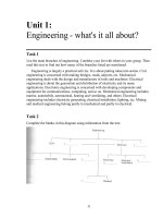
number ::= (From Annex A - A.8.7)
decimal_number
| octal_number
| binary_number
| hex_number
| real_number
real_number* ::=
unsigned_number . unsigned_number
| unsigned_number [ . unsigned_number ] exp [ sign ] unsigned_number
exp ::= e | E
decimal_number ::=
unsigned_number
| [ size ] decimal_base unsigned_number
| [ size ] decimal_base x_digit { _ }
| [ size ] decimal_base z_digit { _ }
binary_number ::=
[ size ] binary_base binary_value
octal_number ::=
[ size ] octal_base octal_value
hex_number ::=
[ size ] hex_base hex_value
sign ::= + | size ::= non_zero_unsigned_number
non_zero_unsigned_number* ::= non_zero_decimal_digit { _ | decimal_digit}
unsigned_number* ::= decimal_digit { _ | decimal_digit }
binary_value* ::= binary_digit { _ | binary_digit }
octal_value* ::= octal_digit { _ | octal_digit }
hex_value* ::= hex_digit { _ | hex_digit }
decimal_base* ::= ’[s|S]d | ’[s|S]D
binary_base* ::= ’[s|S]b | ’[s|S]B
octal_base*::= ’[s|S]o | ’[s|S]O
hex_base* ::= ’[s|S]h | ’[s|S]H
non_zero_decimal_digit ::= 1 | 2 | 3 | 4 | 5 | 6 | 7 | 8 | 9
decimal_digit ::= 0 | 1 | 2 | 3 | 4 | 5 | 6 | 7 | 8 | 9
binary_digit ::= x_digit | z_digit | 0 | 1
octal_digit ::= x_digit | z_digit | 0 | 1 | 2 | 3 | 4 | 5 | 6 | 7
hex_digit ::=
x_digit | z_digit | 0 | 1 | 2 | 3 | 4 | 5 | 6 | 7 | 8 | 9
|a|b|c|d|e|f|A|B|C|D|E|F
x_digit ::= x | X
z_digit ::= z | Z | ?
*Embedded
spaces are illegal.
Syntax 2-1—Syntax for integer and real numbers
2.5.1 Integer constants
Integer constants can be specified in decimal, hexadecimal, octal, or binary format.
Copyright © 2001 IEEE. All rights reserved.
7
IEEE
Std 1364-2001
IEEE STANDARD VERILOG®
There are two forms to express integer constants. The first form is a simple decimal number, which shall be
specified as a sequence of digits 0 through 9, optionally starting with a plus or minus unary operator. The
second form specifies a size constant, which shall be composed of up to three tokens—an optional size constant, a single quote followed by a base format character, and the digits representing the value of the number.
The first token, a size constant, shall specify the size of the constant in terms of its exact number of bits. It
shall be specified as a non-zero unsigned decimal number. For example, the size specification for two hexadecimal digits is 8, because one hexadecimal digit requires 4 bits. Unsized unsigned constants where the
high order bit is unknown (X or x) or three-state (Z or z) are extended to the size of the expression containing the constant.
NOTE—In IEEE Std 1364-1995, unsized constants where the high order bit is unknown or three-state, the x or z was
only extended to 32 bits.
The second token, a base_format, shall consist of a case-insensitive letter specifying the base for the
number, optionally preceded by the single character s (or S) to indicate a signed quantity, preceded by the
single quote character (’). Legal base specifications are d, D, h, H, o, O, b, or B, for the bases decimal, hexadecimal, octal, and binary respectively.
The use of x and z in defining the value of a number is case insensitive.
The single quote and the base format character shall not be separated by any white space.
The third token, an unsigned number, shall consist of digits that are legal for the specified base format. The
unsigned number token shall immediately follow the base format, optionally preceded by white space. The
hexadecimal digits a to f shall be case insensitive.
Simple decimal numbers without the size and the base format shall be treated as signed integers, whereas the
numbers specified with the base format shall be treated as signed integers if the s designator is included or
as unsigned integers if the base format only is used. The s designator does not affect the bit pattern specified, only its interpretation.
A plus or minus operator preceding the size constant is a unary plus or minus operator. A plus or minus operator between the base format and the number is an illegal syntax.
Negative numbers shall be represented in 2 s complement form.
An x represents the unknown value in hexadecimal, octal, and binary constants. A z represents the highimpedance value. See 3.1 for a discussion of the Verilog HDL value set. An x shall set 4 bits to unknown in
the hexadecimal base, 3 bits in the octal base, and 1 bit in the binary base. Similarly, a z shall set 4 bits, 3
bits, and 1 bit, respectively, to the high-impedance value.
If the size of the unsigned number is smaller than the size specified for the constant, the unsigned number
shall be padded to the left with zeros. If the leftmost bit in the unsigned number is an x or a z, then an x or a
z shall be used to pad to the left respectively.
When used in a number, the question-mark (?) character is a Verilog HDL alternative for the z character. It
sets 4 bits to the high-impedance value in hexadecimal numbers, 3 bits in octal, and 1 bit in binary. The
question mark can be used to enhance readability in cases where the high-impedance value is a don t-care
condition. See the discussion of casez and casex in 9.5.1. The question-mark character is also used in userdefined primitive state table. See 8.1.6, Table 8-1.
The underscore character (_) shall be legal anywhere in a number except as the first character. The underscore character is ignored. This feature can be used to break up long numbers for readability purposes.
8
Copyright © 2001 IEEE. All rights reserved.
IEEE
Std 1364-2001
HARDWARE DESCRIPTION LANGUAGE
Examples:
Example 1—Unsized constant numbers
659
’h 837FF
’o7460
4af
//
//
//
//
is
is
is
is
a decimal number
a hexadecimal number
an octal number
illegal (hexadecimal format requires ’h)
Example 2—Sized constant numbers
4’b1001
5 ’D 3
3’b01x
12’hx
16’hz
//
//
//
//
//
//
is a 4-bit binary number
is a 5-bit decimal number
is a 3-bit number with the least
significant bit unknown
is a 12-bit unknown number
is a 16-bit high-impedance number
Example 3—Using sign with constant numbers
8 ’d -6
-8 ’d 6
4 ’shf
-4 ’sd15
//
//
//
//
//
//
//
this is illegal syntax
this defines the two’s complement of 6,
held in 8 bits—equivalent to -(8’d 6)
this denotes the 4-bit number ‘1111’, to
be interpreted as a 2’s complement number,
or ‘-1’. This is equivalent to -4’h 1
this is equivalent to -(-4’d 1), or ‘0001’.
Example 4—Automatic left padding
reg [11:0]
initial begin
a =
b =
c =
d =
end
reg [84:0]
a, b, c, d;
’h
’h
’h
’h
x;
3x;
z3;
0z3;
e = 'h5;
f = 'hx;
g = 'hz;
//
//
//
//
yields
yields
yields
yields
xxx
03x
zz3
0z3
e, f, g;
// yields {82{1'b0},3'b101}
// yields {85{1'hx}}
// yields {85{1'hz}}
Example 5—Using underscore character in numbers
27_195_000
27_195_000
16’b0011_0101_0001_1111
16’b0011_0101_0001_1111
32
32 ’h
’h 12ab_f001
12ab_f001
Copyright © 2001 IEEE. All rights reserved.
9
IEEE
Std 1364-2001
IEEE STANDARD VERILOG®
NOTES:
1) Sized negative constant numbers and sized signed constant numbers are sign-extended when assigned to a reg data
type, regardless of whether the reg itself is signed or not.
2) Each of the three tokens for specifying a number may be macro substituted.
3) The number of bits that make up an unsized number (which is a simple decimal number or a number without the size
specification) shall be at least 32.
2.5.2 Real constants
The real constant numbers shall be represented as described by IEEE Std 754-1985 [B1],1 an IEEE standard
for double-precision floating-point numbers.
Real numbers can be specified in either decimal notation (for example, 14.72) or in scientific notation (for
example, 39e8, which indicates 39 multiplied by 10 to the eighth power). Real numbers expressed with a
decimal point shall have at least one digit on each side of the decimal point.
Examples:
1.2
0.1
2394.26331
1.2E12 (the exponent symbol can be e or E)
1.30e-2
0.1e-0
23E10
29E-2
236.123_763_e-12 (underscores are ignored)
The following are invalid forms of real numbers because they do not have at least one digit on each side of
the decimal point:
.12
9.
4.E3
.2e-7
2.5.3 Conversion
Real numbers shall be converted to integers by rounding the real number to the nearest integer, rather than
by truncating it. Implicit conversion shall take place when a real number is assigned to an integer. The ties
shall be rounded away from zero. For example:
The real numbers 35.7 and 35.5 both become 36 when converted to an integer and 35.2 becomes 35.
Converting -1.5 to integer yields -2, converting 1.5 to integer yields 2.
2.6 Strings
A string is a sequence of characters enclosed by double quotes ("") and contained on a single line. Strings
used as operands in expressions and assignments shall be treated as unsigned integer constants represented
by a sequence of 8-bit ASCII values, with one 8-bit ASCII value representing one character.
1The
10
numbers in brackets correspond to those of the bibliography in Annex H.
Copyright © 2001 IEEE. All rights reserved.
HARDWARE DESCRIPTION LANGUAGE
IEEE
Std 1364-2001
2.6.1 String variable declaration
String variables are variables of reg type (see 3.2) with width equal to the number of characters in the string
multiplied by 8.
Example:
To store the twelve-character string "Hello world!" requires a reg 8 * 12, or 96 bits wide
reg [8*12:1] stringvar;
initial begin
stringvar = "Hello world!";
end
2.6.2 String manipulation
Strings can be manipulated using the Verilog HDL operators. The value being manipulated by the operator is
the sequence of 8-bit ASCII values.
Example:
module string_test;
reg [8*14:1] stringvar;
initial begin
stringvar = "Hello world";
$display("%s is stored as %h", stringvar,stringvar);
stringvar = {stringvar,"!!!"};
$display("%s is stored as %h", stringvar,stringvar);
end
endmodule
The output is:
Hello world is stored as 00000048656c6c6f20776f726c64
Hello world!!! is stored as 48656c6c6f20776f726c64212121
NOTE—When a variable is larger than required to hold a value being assigned, the contents on the left are padded with
zeros after the assignment. This is consistent with the padding that occurs during assignment of nonstring values. If a
string is larger than the destination string variable, the string is truncated to the left, and the leftmost characters will be
lost.
2.6.3 Special characters in strings
Certain characters can only be used in strings when preceded by an introductory character called an escape
character. Table 1 lists these characters in the right-hand column, with the escape sequence that represents
the character in the left-hand column.
Copyright © 2001 IEEE. All rights reserved.
11
IEEE
Std 1364-2001
IEEE STANDARD VERILOG®
Table 1—Specifying special characters in string
Escape
string
Character produced by
escape string
\n
New line character
\t
Tab character
\\
\ character
\"
" character
\ddd
A character specified in 1—3 octal digits
(0 ≤ d ≤ 7)
2.7 Identifiers, keywords, and system names
An identifier is used to give an object a unique name so it can be referenced. An identifier is either a simple
identifier or an escaped identifier (see 2.7.1). A simple identifier shall be any sequence of letters, digits, dollar signs ($), and underscore characters (_).
The first character of a simple identifier shall not be a digit or $; it can be a letter or an underscore. Identifiers shall be case sensitive.
Example:
shiftreg_a
busa_index
error_condition
merge_ab
_bus3
n$657
NOTE—Implementations may set a limit on the maximum length of identifiers, but they shall at least be 1024 characters. If an identifier exceeds the implementation-specified length limit, an error shall be reported.
2.7.1 Escaped identifiers
Escaped identifiers shall start with the backslash character (\) and end with white space (space, tab, newline). They provide a means of including any of the printable ASCII characters in an identifier (the decimal
values 33 through 126, or 21 through 7E in hexadecimal).
Neither the leading backslash character nor the terminating white space is considered to be part of the identifier. Therefore, an escaped identifier \cpu3 is treated the same as a nonescaped identifier cpu3.
Example:
\busa+index
\-clock
\***error-condition***
\net1/\net2
\{a,b}
\a*(b+c)
12
Copyright © 2001 IEEE. All rights reserved.