JIS a 5335 -JAPANESE INDUSTRIAL STANDARD Pretensioned Spun Concrete Pile
Bạn đang xem bản rút gọn của tài liệu. Xem và tải ngay bản đầy đủ của tài liệu tại đây (58.82 KB, 11 trang )
624.154.3.C12.46.666.982.4.033.17
JAPANESE INDUSTRIAL STANDARD
Pretensioned Spun Concrete Pile
© JIS A 5335 – 1979
Translated and published
By
Japanese Standards Association
Printed in Japan
1
A 5335 - 1979
JAPANESE INDUSTRIAL STANDARD
Pretensioned Spun Concrete Pile
1. Scope:
This Japanese Industrial Standard specified the centrifugally spun prestressed concrete piles
manufactured by pretensioning and spinning process, hereinafter referred to as the “PC piles”.
Remark: In this standard, the units and numerical values given in { } are in accordance with
the International System of Units ( SI ), and are given for reference only.
Applicable Standards:
JIS A 1108 – Method of Test for Compressive Strength of Concrete
JIS A 1132 – Method of Marking and Curing Concrete Specimens.
JIS G 3101 – Roller Steel for General Structure.
JIS G 3109 – Steel Bar for Prestressed Concrete.
JIS G 3112 – Steel Bars for Concrete Reinforcement
JIS G 3521 – Hard Drawn Steel Wire
JIS G 3532 – Iron Wires
JIS G 3536 – Uncoated Stress-Relieved Steel Wire and Strand for Prestressed Concrete
JIS R 5210 – Portland Cement
JIS R 5211 – Portland Blast-furnace Slag Cement
JIS R 5313 – Portland Fly-ash Cement
Reference Standard:
JIS Z 8401 – Rules for Rounding Off of Numerical Values
2
A 5335 - 1979
2. Classification
The PC piles shall be classified into Class A, Class B, Class C depending on the value of
cracking bending moment, as given in Table 1.
Table 1
Class
A
B
C
A
B
C
A
B
C
A
B
C
A
B
C
A
B
C
A
B
C
A
B
C
A
B
C
A
B
C
Cracking bending
moment
tf.m (KN/m)
2.5
3.5
4.0
3.5
5.0
6.0
5.5
7.5
9.0
7.5
11.0
12.5
10.5
15.0
17.0
17.0
25.0
29.0
27.0
38.0
45.0
40.0
55.0
65.0
75.0
105.0
120.0
120.0
170.0
200.0
{24.5}
{34.3}
{39.2}
{34.3}
{49.0}
{58.8}
{53.9}
{73.6}
{88.3}
{24.5}
{107.9}
{122.6}
{103.0}
{147.1}
{166.7}
{166.7}
{245.2}
{284.4}
{264.8}
{372.7}
{441.3}
{392.3}
{559.4}
{637.4}
{735.5}
{1029.6}
{1176.8}
{1176.8}
{1667.1}
{1961.3}
Outside
Diameter
(mm)
Thick
-ness
7
8
9
10
11
12
13
14
15
300
60
O
O
O
O
O
O
O
-
-
350
65
O
O
O
O
O
O
O
O
O
400
75
O
O
O
O
O
O
O
O
O
450
80
O
O
O
O
O
O
O
O
O
500
90
O
O
O
O
O
O
O
O
O
600
100
O
O
O
O
O
O
O
O
O
700
110
O
O
O
O
O
O
O
-
-
800
120
O
O
O
O
-
-
-
-
-
1000
140
O
O
O
O
-
-
-
-
-
1200
150
O
O
-
-
-
-
-
-
-
Length (m)
3
A 5335 - 1979
3. Quality
3.1 Appearance: The PC piles shall be free from defects such as detrimental flaws or cracks.
3.2 Bending Strength
3.2.1 Main Body: The main body of the PC piles shall be subjected to the bending strength
test specified in 3.1, and shall withstand the cracking bending moment given in Table 1 without
showing any cracks (1).
The breaking bending moment shall be not less than 1.5 times the cracking bending moment
given in Table 1 for Class A, not less than 1.8 times for Class B and not less than 2.0 times for
Class C.
Note (1) The crack generally discernible by naked eyes is about 0.05 mm wide.
3.2.2 Jointing End The jointing end shall be as follows:
(1) The bending strength of jointing end shall be not less than the bending strength
specified in 3.2.1.
(2) The deflection and the deflection curve when the bending moment of the jointing
end has reached the cracking bending moment given in Table 1 in the bending
strength test of jointing end shall be approximately equal to those measured prior to
test for the PC pile which is not fitted with jointing end.
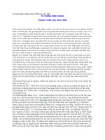
4. Shape and Dimensions:
4.1 Shape: The PC pile shall be composed of the main body of hollow cylindrical shape as
shown in Fig. 1, and shall have the suitable pointed end (2) jointing ends (3) or head (4), as
necessary. The outside diameter and wall thickness of main body shall be uniform in every cross
section over the whole length.
Fig. 1
Length
Wall thickness
Head or jointing end
Pointed end or jointing end
Notes: (2) There are various types of pointer end, e.g. closed type, open type, etc. Its length
shall be included in that of the PC pile.
(3) The length of jointing end shall be included in that of the PC pile.
(4) The length of head shall be included in that of the PC pile.
4
A 5335 - 1979
4.2 Dimensions: The dimensions of the PC piles shall conform to Table! and the dimensional
tolerances to Table.
Table 2
Unit: mm
Tolerance
Outside
diameter
300 to 600
700 to 1200
Length
± 0.3 (%) of the length of
PC pile
Outside
diameter
+5
-5
+7
-4
Wall thickness
÷ Not specified
-1
Remark 1. The outside diameter of PC pile is defined as the average of two measurements taken
along the axes at right angle, to each other in a cross section.
2. The wall thickness of PC is defined as the average of two measurements taken along
the axes at right angle, to each other in a cross section.
5. Materials:
5.1 Cement: The cement used shall be equal to or superior to it specified in JIS R 5210; JIS R
5211 or JIS R 5213.
5.2 Aggregates: Aggregates shall be clean, rigid and durable, and shall not contain any
detrimental amount of dust, mud, salts, organism or else. The maximum size of coarse aggregate
shall be not more than 30 mm and not more than 2/5 of the wall thickness of PC pile.
5.3 Water: The water shall not contain any detrimental amount of oil, acids, salts, organism or
else.
5.4 Admixtures: Admixtures, if used, shall be of such nature that will not give adverse effect to
the product. Calcium chloride shall not be used.
5.5 PC Steel: The PC steel used for PC piles shall conform to either of the following:
(1) Deformed bar specified in JIS G 3109
(2) JIS G 3536
5.6 Reinforcement: The reinforcement used for PC piles shall conform to any of the following or
be equivalent or it in mechanical properties.
(1) JIS G 3112
(2) JIS G 3101
(3) JIS G 3521
(4) Ordinary iron wires specified in JIS G 3532
5
A 5335 - 1979
6. Manufacture:
6.1 PC Steels and Reinforcement:
6.1.1 The PC steels and reinforcement in axial direction shall have a reinforcement ratio not
less than 0.4% in the aggregate cross-sectional area, and shall be arranged as uniformly as
practicable round the concentric circumference in every cross section of the PC pile, in due
consideration of minimizing the variation of bending strength of the PC pile by radial direction. The
clearance between the PC steels and reinforcement shall be not less than steel diameter and, at the
same time, not less than 4/3 times the largest size of the coarse aggregates.
6.1.2 The spiral additional bars shall be arranged outside the axial PC steels and
reinforcement. The additional bars shall be not less than 3 mm in diameter and be arranged at a
pitch not more than 150mm.
6.1.3 The covering shall be not less than 15 mm.
6.1.4 For the PC steels and reinforcement, before being set up, free rust, oil, etc. which may
hinder the adhesion of concrete shall be removed and they shall be set up in such a manner that they
are fixed in the right position.
6.2 Concrete:
6.2.1 The quality of concrete used for manufacturing the PC piles shall be not less than
500kgf/cm2 (4.90 KN/cm2) in compressive strength when tested for a specimen cured in the same
way as the product.
The compressive strength testing shall be made for the specimen of 10 cm in diameter and
20cm in height in accordance with JIS A 1132 and JIS A 1108.
6.2.2 The materials used for the concrete shall be measured by mass. Water and liquid
admixtures may be measured by volume.
6.2.3 The concrete shall be mixed thoroughly in a concrete mixer.
6.3 Forming:
6.3.1 The PC piles shall be formed according to the following procedure: Position the set up
PC steels and reinforcement in the mould, pour the concrete in it so as the wall thickness of pile will
be uniform, and compact the concrete into shape by centrifugal force. Before the process abovementioned, the PC steels shall be pretensioned to the required stress.
6.3.2 The pointed end, jointing, ends or head, if fined to the PC pile, shall be in correct
position, and be fitted to make integral part with the body.
6
A 5335 - 1979
6.4 Curing: The curing shall be carried out by such a method that may not affect adversary the
quality of the product.
6.5 Method of Prestressing:
6.5.1 The PC steels shall be strained in right positions, and the both ends shall be fixed
perfectly so as not to loosen the steels until they are prestressed.
6.5.2 The initial straining force shall be enough to cause the required effective prestress, and
be not more than 0.7 time the tensile load or not more than 0.8 time the yield load of the PC steel.
6.5.3 The prestress shall be introduced gradually.
6.5.4 The compressive strength of concrete when it is prestressed shall be not less than 3
times the prestress given and not less than 250 kgf/cm2 (2.45 KN/cm2). In this case, the compressive
strength testing shall be made in accordance with JIS A 1108 for specimen of 10 cm in diameter and
20 cm in height cured in the same manner as for the product.
7. Jointing End:
7.1 The jointing end of PC pile shall be of a construction having equivalent performance to
the main body.
7.2 The end of PC steels shall be fixed to the metal parts at the jointing ends.
7.3 The jointing end shall be made so that its end face is perpendicular the longitudinal axis
of the PC pile.
7.4 The tolerance on outside diameter of the jointing end shall be within $0.5 mm and $3
mm to the outside diameter of PC pile specified in Table 1.
The difference between the outside diameters of joint of the piles when jointed together shall
be not more than 2mm.
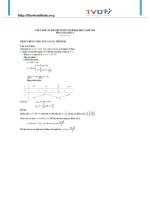
8. Bending Strength Test:
8.1 The bending strength test of main body shall be made by the application of vertical load
P to the middle center of span, on the PC pile laid on two supports which has a span equal to 3/5 of
its length, as shown in Fig.
Any countermeasure may be taken to prevent the occurrence of local fractures at the loading
or supporting points before the PC pile breaks by bending.
The bending moment shall be calculated from the following equation:
7
A 5335 - 1979
M=
Where:
M:
P:
L:
m:
q:
1
P ⎛3
⎞
qmL$
⎜ L −1⎟
4
4 ⎝5
⎠
bending moment (tf.m) (kN.m)
load (tf) (kN)
length of PC pile (m)
mass of PC pile (t) (see Reference Table)
acceleration due to gravity (1 tf/t) (9.81 m/s2)
Fig. 2
Loading method
P
Load
0.5m 0.5m
3/10L
3/10L
1/5L
Span 3/5L
1/5L
8.2 The breaking bending moment shall be obtained from the equation in 8.1 using the
largest value of the load P observed until the PC pile breaks.
8.3 The bending strength test of joint shall be made in accordance with 8.1, provided that the
joint is positioned at the center of the span.
9. Inspection:
9.1 The inspection shall be made on appearance, shape, dimensions, bending strength of
main body, bending strength of jointing end, arrangement of PC steels and reinforcement.
9.2 The inspection on appearance, shape and dimensions shall be made for whole products,
and those which meet the requirements of 3.1 and 4 shall be decided as acceptable.
9.3 Bending Strength of Main Body and Jointing End:
9.3.1 The cracking inspection for main body shall be made by making the cracking testing
accordance with 8.1 for the two PC piles sampled from a lot of PC piles, and the whole lot shall be
decided as acceptable, if both two meet the requirements of 3.2. In the case where either of the two
falls to meet the requirements of 3.2, additional four piles sampled from the lot shall be subjected to
cracking test, and the whole lot shall be decided as acceptable, if all the four meet the requirements.
The size of lot shall be determined upon agreement between the parties concerned.
8
A 5335 - 1979
9.3.2 In the breaking inspection of main body, either of the initial two samples shall be
tested in accordance with 8.1, and the whole lot shall be decided as acceptable, if they meet the
requirements of 3.2.
The breaking inspection may be omitted, subject to an agreement between the parties
concerned.
9.3.3 The jointing end shall be inspected similarly to the main body. This inspection,
however, may be omitted, subject to an agreement between the parties concerned.
9.4 The inspection on arrangement of the PC steels and reinforcement shall be made for the
PC pile which has been subjected to the breaking inspection, and the arrangement shall be decided
as acceptable, if it meets the requirement of 6.1.
On that occasion, the wall thickness of the broken part in the PC pile shall also be inspected.
10. Designation:
The PC piles shall be designated in the order of the symbol PR. indicating pretension
process, classification, outside diameter (mm) and length (m).
Example: PR-A 500 - 11.
11. Marking:
The PC piles shall be marked with the following particulars:
(1) Designation
(2) Manufacture’ s name or its abbreviation
(3) Name or abbreviation of manufacturing works.
(4) Date of forming
9
A 5335 - 1979
Reference: The following Reference Table shows the long-term acceptable axial loads and the
masses of the PC piles for the reference of practical use.
The masses of PC Piles have been calculated from the following equation, on the
assumption that the mass for unit volume of PC pile is 2.6 t/m3 and π = 3.14, and rounded off to the
second decimal place in accordance with JIS Z 8401.
m = 2.6 π t (D - t)L
Where:
m:
D:
t:
L:
mass (t).
outside diameter (m)
wall thickness (m)
length (m)
Reference Table
Outside
diameter
mm
Long term allowable
axial load tf (kN)
Class A
Class B
Mass
Class C
7m
8m
9m
10m
11m
12m
13m
14m
15m
300
50
{490}
45
{441}
40
{392}
0.82
0.94
1.06
1.18
1.29
1.41
1.53
-
-
350
60
{588}
55
{539}
55
{539}
1.06
1.21
1.36
1.51
1.66
1.81
1.97
2.12
2.27
400
80
{785}
75
{736}
70
{686}
1.39
1.69
1.79
1.99
2.19
2.39
2.59
2.79
2.98
450
100
{981}
90
{883}
85
{834}
1.69
1.93
2.17
2.42
2.66
2.90
3.14
3.38
3.62
500
125
{1226}
115
{1128}
105
{1030}
2.11
2.41
2.71
3.01
3.31
3.62
3.92
4.22
4.52
600
170
{1667}
155
{1520}
145
{1422}
2.86
3.27
3.67
4.08
4.49
4.90
5.31
5.71
6.12
700
220
{2158}
200
{1961}
190
{1863}
3.71
4.24
4.77
5.30
5.83
6.36
6.89
-
-
800
280
{2146}
250
{2452}
235
{2305}
4.66
5.33
6.00
6.66
-
-
-
-
-
1000
415
{4070}
370
{3629}
350
{3432}
6.88
7.86
8.85
9.83
-
-
-
-
-
1200
540
{5296}
490
{4805}
465
{4650}
9.00
10.29
-
-
-
-
-
-
-
A 5445-1979
Edition 1
Japanese Text
Established by Minister of International Trade and Industry
Date of Establishment: 1968-06-01
Date of Revision: 1979-11-01
Date of Public Notice in Official Gazette: 1979-11-30
Investigated by:
Japanese Industrial Standards Committee
Divisional Council on Civil Engineering
This English translation is published by:
Japanese Standards Association
1-24, Akasaka 4, Minato-ku,
Tokyo 107 Japan
© JSA, 1980