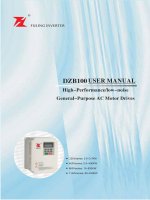
tài liệu biến tần Fuling DZB100
Bạn đang xem bản rút gọn của tài liệu. Xem và tải ngay bản đầy đủ của tài liệu tại đây (963.36 KB, 83 trang )
220Vseries: 0.5~3.7KW
400Vseries: 0.5~400KW
660Vseries: 15~630KW
1140Vseries: 55~630KW
TABLE OF CONTENTS
Preface
Chapter 1 Introduction
Chapter 2 Installation and Wiring
Chapter 3 Digital Keypad Operation
Chapter 4 Start Up
Chapter 5 Summary of Parameter Settings
Chapter 6 Parameter Settings
Chapter 7 Troubleshooting and Fault information
Chapter 8 Quality Guarantee
Appendix A Standard Specifications
Appendix B Serial Communications
Appendix C Dimensions
Appendix D Accessories List
DZB100 Series
Preface
Preface
Thank you for choosing DZB100 Series high-performance AC Motor Drives. DZB100 Series are
manufactured by adopting high-quality components, material and incorporating the latest
microprocessor technology available.
Getting Started
This manual will be helpful in the installation, parameter setting, troubleshooting, and daily
maintenance of the AC motor drives. To guarantee safe operation of the equipment, read
the following safety guidelines before connecting power to the AC drives. Keep this
operating manual handy and distribute to all users for reference.
! WARNING
ATTENTION: Always read this manual thoroughly before using DZB100 series AC Motor Drives.
DANGER! AC input power must be disconnected before any maintenance.
WARNING! Do not connect or disconnect wires and connectors while power is applied to the circuit.
Maintenance must be performed by qualified technicians.
WARNING! To avoid personal injury, do not remove the cover of the AC motor drive until all of
thedigital keypad "DISPLAY LED" lamps are off. The DC-link capacitor remains
charged with a hazardous voltage even after input power is removed.
ATTENTION: Grounding the DZB100B drive is done by connecting the Earth Ground to the
drive ground terminal .
CAUTION: There are highly sensitive components on the printed circuit boards. These components
are especially sensitive to ESD (electrostatic discharge). To avoid damage to the drive ,
do not touch components or the circuit boards until static control precautions have been
taken.
CAUTION: Never connect the main circuit output terminals U, V, and W directly to the AC main
circuit power supply as this will damage the drive .
CAUTION: Do not apply the antirust to screws for fastening drives; Please clean the drives and
screws with dry cloth or alcohol, not with synthetic cleaner. Fasten the screws with
washers and rated torque lest the enclosure corners of drives be distorted.
This manual is for DZB100 Series AC Motor Drive.
-1-
DZB100 Series
Introduction
Chapter 1 Introduction
The purpose of this chapter is to provide specific, yet simple information to unpack , install the
AC drive. This chapter contains information on the following:
1.1 Receiving, Transportation, and Storage
1.2 Nameplate Information
1.1 Receiving, Storage and Transportation
The AC motor drive has gone through rigorous quality control tests at the factory before shipment.
After receiving the AC drive, check for the following.
Receiving
1.Check to make sure that the package includes an AC drive,the User Manual,dust covers and
rubber bushings.
2.Inspect the unit to insure it was not damaged during shipment.
3.Make sure that the part number indicated on the nameplate corresponds with the part number
of your order.
Storage
The AC Drive should be kept in the shipping carton before installation. In order to retain the
warranty coverage, the AC drive should be stored properly when it is not to be used for an
extended period of time. Some storage suggestions are:
1.Store in a clean, dry location.
2.Store within an ambient temperature range of -20 C to +65 C.
3.If possible, store in an air-conditioned environment where the relative humidity is less than
95%, non-condensing.
4.Do not store the AC drive in places where it could be exposed to corrosive gases.
5.Do not store the AC drive on a shelf or on an unstable surface.
Transportation
Temperature: -25
C to +70
C; R.H.: 0% to 95%;
Air Pressure: 70kPa to 106kPa.
-2-
DZB100 Series
Introduction
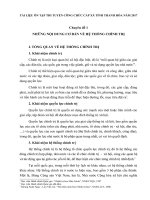
1.2 Nameplate Information
Example:
MODEL:DZB100B0075L4A
INPUT: 3PH 380V 50/60Hz
OUTPUT: 3PH 0~380V 0~400Hz
POWER: 7.5KW 18.0A
S/N:FL75/05058888
TAIZHOU FULING ELECTROMOTOR CO.,LTD.
Description of AC Motor Drive Model:
DZB100 B 0075 L
4 A
Function level code A
braking unit inside
B non braking unit
C special model
Input voltage 2-220V 4-400V
6-660V 11-1400V
Freq. Range L 0-400.0Hz H
Applicable motor capacity
B Series
Series name
Description of Serial Number:
FL75 05
05
0001
Production number
Production month
Production year
Model Name:FL75-7 5 Model
-3-
0-2000Hz
0015:1.5KW 0075:7.5KW
DZB100 Series
Introduction
Description of Serial Name:
Series Code
Explanation
Applicable Motor
B Series
High-Performance General-Purpose AC Motor Drives
0.55~400KW
P Series
Specific AC Motor Drives For Fan&Pump
7.5~400KW
S Series
Specific AC Motor Drives For Plastic Molding Machinery
7.5~280KW
H Series
Specific AC Motor Drives For High-Speed Motor
2.2~30KW
(3.0~40KVA)
T Series
Specific AC Motor Drives For The Gating Of Elevator
0.55~2.2KW
L Series
Specific AC Motor Drives For Bobbin Machinery
0.55~75KW
D Series
Specific AC Motor Drives For Variable Power
15~220KVA
PP Series
Specific AC Motor Drives For Isobarically Water Supply
3.7~400KW
M Series
High-Performance Micro-TypeAC Motor Drives
0.55~2.2KW
-4-
DZB100 Series
Installation and Wiring
Chapter 2 Installation and Wiring
Chapter 2 provides the information needed to properly install and wire the AC drive.
Make sure that the AC drive is wired according to the instructions contained in this chapter.
The instructions should be read and understood before the actual installation begins.
2.1 Installation Requirements
2.2 Wiring
2.3 Basic Wiring Diagram
2.1 Installation Requirements
Install the AC drive vertically to provide proper ventilation. Adequate space isrequired between
the drive and a wall or other equipment. The figure below shows the minimum space needed.
All enclosures must provide adequate ventilation and the internal ambient temperature
must be kept at 40
or below.
AIR
Wiring orifice
PRGM
RESET
FWD
REV
FUNC
DATA
JOG
RUN
STOP
AIR
Caution: The AC drive should be installed in an environment that is:
1.protected from rain or moisture;
2.protected from direct sunlight;
3.protected from corrosive gases or liquids;
4.free from airborne dust or metallic particles;
5.free from vibration;
6.free from magnetic noise
7.temperature: -10
C to +40
C; R.H.: 0% to 90%; air pressure: 86kPa to 106 kPa
-5-
DZB100 Series
Installation and Wiring
2.2 Wiring
Main Circuit Wiring
(1) Power terminal block designations
Power input and output may be connected via a nine or ten position termina block. The pin
assignments are as follows:
Model
Applicable motor
capacity
FL08
0.55 ~0.75 KW(220V Series)
Power terminal pin assignments
R
1.5KW (220V Series )
FL22
0.75~2.2KW(380V Series)
S
U
T
W
Motor
Connection
AC Input Line
Terminals
Earth
Ground
V
BR+ BRBreaking
Resistor
0.75~1.5KW (220V Series )
R
FL28
0.75~1.5KW(380V Series)
Earth
Ground
S
T
BR+ BR-
AC Input Line
Terminals
U
V
W
Motor
Connection
Breaking
Resistor
2.2~3.7KW(220VGrade)
E
FL37
2.2~5.5KW (380V Series)
Earth
Ground
R
S
T
BR+ BR-
AC Input Line
Terminals
Breaking
Resistor
R
BR+ BR-
U
V
W
Motor
Connection
FL75
E
7.5~15KW(380V Series)
FL015
FL030
Earth
Ground
R
18.5~30KW(380V Series )
S
T
AC Input Line
Terminals
S
T
FL045
37~45KW (380V Series )
FL075
55~75KW(380V Series)
FL132
93~132KW(380V Series )
FL160
132~160KW(380V Series)
R
187~280KW(380V Series )
T
AC Input Line
Terminals
R
FL220
S
S
T
AC Input Line
Terminals
-6-
P2
DC-
U
DC+ DC-
U
V
Motor
Connection
Breaking
Unit
V
W
V
W
Motor
Connection
Breaking
Unit
U
V
Motor
Connection
Breaking
Resistor
P1
AC Input Line
Terminals
U
W
Motor
Connection
Earth
Ground
W
Earth
Ground
E
Earth
Ground
DZB100 Series
Installation and Wiring
(2) Power block terminal designations
Description
Terminals
R
S
T(L
U
V
W
N)
AC input line terminals
Motor connection
BR+(DC+) BR-
Connection for the regenerative resistor (option)
P1(DC+) DC-
Connection for the braking unit (option)
P1 P2
Connection for the DC Link Reactor (option)
Ground
(3) Attention:
1.The user must provide a circuit breaker or disconnect switch and fuses in accordance with all
applicable electrical codes.
2.Make sure that the leads are connected correctly and the AC drive is properly grounded.
(Ground leads should be at least the same size wire as the input leads R, S, and T.)
3.Use ground leads that comply with AWG standards. Make the length of these ground leads as
short as possible.
4.Should several AC drive units be installed side by side, all the units should be grounded directly
to the ground poles. Do not form a loop with the ground leads.
5.Make sure that the power source supplies the correct voltage and is capable of supplying the
required current to the AC drive. Refer to specification for Rated AC Input Power .Motor
Voltage should match the line voltage.
6.For single phase applications, the AC input line can be connected to any two of the three input
terminals R, S, T. A single phase DZB100B drive can be powered from three phase as well as
single phase.
Note: This drive is not intended for use with single-phase motors.
7.When the AC drive output terminals U, V, and W are connected to the motor terminals U, V, and
W, respectively, the motor will rotate counter-clockwise (viewed from the shaft of the motor as
shown below) if a forward operation command is entered (FWD lamp is ON).
-7-
DZB100 Series
Installation and Wiring
8.To reverse the direction of rotation, interchange any two connections of the three motor leads.
9.The control lines and power lines (R,S,T;U,V,W;P,N,BR+,BR-) should be separated and avoid
parallel wiring lest it should generate noise and cause mis-operation.
Caution: Do not attach or remove wiring or connectors when power is applied to the AC drive.
Caution: Do not monitor the signals at any point on the circuit board while the AC drive is in
operation.
Caution: Do not connect the AC input to any of the U, V, W terminals, as this will damage the AC
drive.
-8-
DZB100 Series
Installation and Wiring
Control Circuit Wiring
(1) Control terminal block designations
The control leads must be routed separately from the power supply and motor leads.
They must not be fed through the same cable conduit.
Terminal Symbol
A
B
FWD
A
B
10V
C
REV DCM
C
M
FWD REV DCM M
VI
M
1
1
M
2
CI
M
2
M
3
3
RST
FM
RST
EF
ACM
EF
MO1
MO 2 M C M
TRG DCM DFM
EV
S G + SS
GG -
TRG DFM DCM MO 1 MO 2 MCM 10V
VI
CI
FM ACM EV
SG+ SG-
(2) Control terminal block descriptions
Close Contacts
Terminals
Terminals Use
Function
A-B
Multi-function indication output contact
B-C
Multi-function indication output contact
REV-DCM
Reverse / Stop
"Open"
stop,"Close"
Reverse
FWD-DCM
Forward / Stop
"Open"
stop, "Close"
Forward
MI1-DCM
Multi-function input 1
MI2-DCM
Multi-function input 2
MI3-DCM
Multi-function input 3
MI4 ( EF )-DCM
Multi-function input 4
RST-DCM
Reset
"Close"
DFM-DCM
Digital frequency meter
Digital frequency output (0, +10 V)
TRG-DCM
Counter trigger input
"Open"
MO 1-MCM
Multi-function PHC output 1
MO 2-MCM
Multi-function PHC output 2
Refer to F1-45, 46
(open collector output)
10V-ACM
Power supply for speed setting
+10 V (20 mA max. output current)
VI-ACM
Analog voltage input
0~10 V (Max. output freq.) input
CI-ACM
Analog current input
4~20 mA (Max. output freq.) input
FM-ACM
Analog frequency/current meter
0 ~10 V (Max. output freq.) output
SG+-SG-
Serial communication interface
RS-485 serial port
EV-DCM
Auxiliary control power source
DC 20V ~ 24V (50mA Max.)
Refer to Chapter 5, F1-57
Refer to Chapter 5,
F1-39, 40, 41, 42
Reset
"Close":(counter value)+1
Note: Use twisted-shielded or twisted-pair shielded-lead wires for the control signal.
It is recommended to run signal wiring in a separate steel conduit.
The shield wire should only be connected at the drive.
-9-
DZB100 Series
Installation and Wiring
2.3 Basic Wiring Diagram
Users must connect wires according to the following circuit diagram shown below. Do not plug a
Modem or telephone line to the RS-485 communication port, permanent damage may result.
Terminals 1 & 2 are the power sources only for the optional copy keypad and should not be used
while using RS-485 communication.
Braking resistior(option)
Use a disconnect
and fuse
BR+
Power source R
3 phase
200-240V or S
380-480V
50/60Hz
T
BR-
R
DC 20V ~ 24V ( 50mA Max. )
Multi-function input 1
U
S
V
T
W
EV
E
M
Grounding
MI1
Multi-function input 2
FM
MI2
Multi-function input 3
+
-
MI3
REV/STOP(REV/STOP)
FWD/STOP(RUN/STOP)
Reset
ACM
REV
A Multi-function indication
output contact
C AC 250V 2A below
B DC 30V 2A below
FWD
RST
Multi-function input 4
( External fault)
MI4
Counter trigger input
Digital signal common
Analog frequency/
current meter
DC0-10V
(EF)
TRG
M01
DCM
M02
Multi-function PHC output
48V 50mA below
MCM Digital frequency meter
8888
DFM
10V
3
Frequency setting
0~10VDC
Vr:3k~5k
Current input
4~20mA
2
VI
MCU
VI
DCM
VCC
WR
Panel Resistor SG+
Signal+
SG-
Signal-
CI
1
RS-485 Serial interface
ACM
shows main circuit
shows control circuit
0.75KW 5.5KW
-10-
DZB100 Series
Installation and Wiring
Braking unit (option)
Use a disconnect
and fuse
Braking resistior
P1
Power source R
3 phase
200-240V or S
380-480V
50/60Hz
T
P2
U
DC Link Reactor (option)
DC 20V ~ 24V ( 50mA Max. )
Multi-function input 1
S
V
T
W
EV
E
M
Grounding
MI1
Multi-function input 2
FM
MI2
Multi-function input 3
+
-
MI 3
REV/STOP(REV/STOP)
FWD/STOP(RUN/STOP)
Reset
Multi-function input 4
( External fault)
ACM
REV
MI 4 (EF)
Digital signal common
TRG
M01
DCM
M02
MCU
10V
3
Analog frequency/
current meter
DC0-10V
A Multi-function indication
output contact
C AC 250V 2A below
B DC 30V 2A below
FWD
RST
Counter trigger input
Frequency setting
0~10VDC
Vr:3k~5k
Current input
4~20mA
DC-
R
MCM Digital frequency meter
8888
DFM
VCC
WR
VI
Multi-function PHC output
48V 50mA below
DCM
Panel Resistor
2
VI
S1
CII
CI
1
VII
ACM
S2
Frequency setting
4~20mA
Frequency setting
0~10V
shows main circuit
Signal+
SG-
SignalRS-485 Serial interface
shows control circuit
7.5KW 132KW
-11-
SG+
DZB100 Series
Installation and Wiring
Use a disconnect
and fuse
Power source R
3 phase
200-240V or S
380-480V
50/60Hz
T
DC 20V ~ 24V ( 50mA Max. )
Multi-function input 1
R
U
S
V
T
W
EV
E
Grounding
MI1
Multi-function input 2
FM
MI2
Multi-function input 3
+
-
MI3
REV/STOP(REV/STOP)
ACM
REV
FWD/STOP(RUN/STOP)
RST
Multi-function input 4
( External fault)
Analog frequency/
current meter
DC0-10V
A Multi-function indication
output contact
C AC 250V 2A below
B DC 30V 2A below
FWD
Reset
MI4 (EF)
Counter trigger input
Digital signal common
TRG
M01
DCM
M02
MCU
10V
3
Frequency setting
0~10VDC
Vr:3k~5k
Current input
4~20mA
M
2
VI
DCM
Panel Resistor
S1
CI
CI
1
VI
ACM
S2
Frequency setting
4~20mA
SG+
Signal+
SG-
Signal-
Frequency setting
0~10V
shows main circuit
Notes :
MCM Digital frequency meter
8888
DFM
VCC
WR
VI
Multi-function PHC output
48V 50mA below
RS-485 Serial interface
shows control circuit
132KW 315KW
Refer to F1-39, 40, 41 on page 45.
Refer to F1-38 on page 44.
Refer to F1-45, 46 on page 48 and F1-63, 64, 66 on pages 55 and 56.
Refer to F1-43 on page 47.
Refer to F1-00 on page 28, F1-48, 49, 50 on page 49.
Refer to F1-42, 44 on pages 46 and 47.
Refer to F1-57 on page 53.
Refer to F1-45, 46 on page 48.
Refer to F1-00, 01 on page 28, F1-77, 78 on page 60 and 61 .
-12-
DZB100 Series
Digital Keypad Operation
Chapter 3 Digital Keypad Operation
Chapter 3 describes the various controls and indicators found on the digital keypad of the DZB100
AC drive. The information in this chapter should be read and understood before performing the
start-up procedures described in Chapter 4.
3.1 Description of the Digital Keypad
3.2 Explanation of Screen Display
3.3 Digital Keypad Operating Modes & Programming steps
3.1 Description of the Digital Keypad
Digital Keypad Parts and Functions
This digital keypad module includes two parts: display panel and a keypad. The display panel
allows the user to program the AC drive, as well as view the different operating parameters. The
keypad is the user interface to the AC motor drive. Refer to the following figure for a description
of the different parts.
RUN
STOP
JOG
FWD
REV
LED indication
LED display
Red lamp lights during RUN,
STOP, JOG, FWD, or
Indicates frequency, motor current
REV operation.
and alarm contents.
Program / Reset key
Up and down keys
PRGM
RESET
Sets the parameter number or changes
the numerical data such as the
frequency reference.
Jog key
While pressing this key, jog
speed is available.
Forward / Reverse key
FUNC
DATA
JOG
REV
FWD
RUN
STOP
Selects FWD or REV operation.
Selects normal mode / program mode.
Displays the motor drive status, such
as output freq., selects the
parameters, FWD/REV or output
current, etc.
Function / Data key
Displays the motor drive status, such as frequency
reference, output frequency or output current under
the normal mode; or sets parameters under the
program mode.
Digital Operator
Run key
Stop key
Starts inverter drive
operation.
Stops AC Motor Drive operation.
-13-
DZB100 Series
Digital Keypad Operation
Key
Description
PRGM
RESET
Program / Reset
Used to select the Normal mode of operation or to program the AC drive when
either the drive is running or has stopped. Switch to the PRGM mode to select
a parameter or change the setting of a parameter. If the AC drive has stopped
due to a fault, press this button to reset the drive.
FUNC
DATA
Function / Data
Displays information on the AC drive status such as the reference frequency,
output frequency, or output current in the normal mode. While the drive is in
the Program Mode, press this key once to display the current parameters.
After changing the parameters, press this key again to store the new parameters.
FWD
REV
Forward / Reverse
Used to toggle between forward and reverse operation.
Pressing this key will cause the motor to ramp down to 0 Hz and then ramp up
to the preset speed in the opposite direction. By default, the digital keypad
controls the AC drive forward/reverse operation.
To control the forward/reverse operation via the control terminal block,
change the F1-01 parameter to 0001 or 0002 .
JOG
Jog
Used to start the AC drive, then run at the jog frequency as set by the parameter
specified under F1-23 [Jog Frequency].
RUN
Run
Used to start the AC drive operation.
This key has no effect when the drive is set to terminal run.
STOP
Stop
Used to stop the AC drive operation.
Up / Down
Press the "Up" or "Down" button to change parameter settings.
These keys may also be used to scroll through different operating values or
parameters.
Note: Pressing the "Up" or "Down" button momentarily changes the parameter settings in
increments. Press and hold down either of these keys to rapidly run through the possible
settings.
-14-
DZB100 Series
Digital Keypad Operation
3.2 Explanation of Screen Display
Explanation of Displayed Messages
Displayed Message
Description
Displays the AC drive output frequency controlled by the Maximum
Output Frequency (F1- 03), Jog Frequency (F1- 16), or by the
Multi-Function Input Terminals (F1-39-41).
If the frequency source originates from the Digital keypad, the user can
use either the
or
key to set the frequency.
Displays the output frequency present at terminals U, V, and W.
Displays the input voltage.
Displays the custom unit (n), where n = P * F1-.65.
Displays the internal counter value (r).
Note: Refer to Chapter 5, F1-45, 46, 63 - 66 for a detailed description
of the above.
Displays the output current present at terminals U, V, and W
Displays the specified parameter number. The actual parameter value
may be displayed by pressing the FUNC
key.
DATA
Displays actual value stored within the specified parameter.
Press the FUNC
key to store the value of the specified parameter.
DATA
The display will read Fd (as shown) for approximately 1 second if
the input has been accepted. After a parameter value has been set,the
new value is automatically stored in memory. To modify an entry, use
or
key.Then press the FUNC
key.
DATA
-15-
DZB100 Series
Digital Keypad Operation
Explanation of the LED Indicators
RUN STOP JOG FWD
REV
Red lamp lights during REV operation.
Red lamp lights during FWD operation.
Red lamp lights during JOG.
Red lamp lights by pressing STOP.
Red lamp lights by pressing RUN.
RUN or STOP lamp indication is defined by the following operation
Inverter output frequency
STOP
STOP
RUN
KEY
KEY
KEY
Frequency command
RUN
LAMP
STOP
LAMP
BLINK
LIGHT
LIGHT OFF
FWD or REV lamp changes indication is defined by the following operation
FWD
Inverter output frequency
REV
RUN
FWD
REV
FWD
LAMP
REV
LAMP
LIGHT
BLINK
-16-
LIGHT OFF
DZB100 Series
Digital Keypad Operation
3.3 Digital Keypad Operating Modes & Programming steps
Pressing the RUN key after power on will cause the AC drive to operate at 60 Hz, which is the
factory default setting. Use the STOP key to halt operation. Refer to the Basic Wiring Diagram
in Chapter 2 for information on the wiring connection.
To change the operating frequency, proceed as follows:
The operating frequency may be changed in either the
STOP
MODE
MODE
Increase the frequency
Decrease the frequency
NOTES:Display changes every time
or
key is pressed.
-17-
or
RUN
mode.
DZB100 Series
Digital Keypad Operation
Setting parameters:
Indication after power on.
Press
FUNC
DATA
key
Press
FUNC
DATA
Press
PRGM
RESET
PRGM
RESET
key
key
key
Output frequency
Frequency command
Press
FUNC
DATA
Press
Output current
Press
PRGM
RESET
key
key
key to set the parameter setting number.
Press
PRGM
key
RESET
return to the normal
operation mode.
(Data entered will not be stored.)
Press
PRGM
key
RESET
return to the normal
operation mode.
(Data entered will not be stored.)
Press
FUNC
DATA
key to display parameter data.
Press
key to set the parameter data.
Press
Press
-18-
FUNC
DATA
key to store the data.
DZB100 Series
Start Up
Chapter 4 Start Up
This chapter describes the steps needed to start the AC drive and typical adjustment and verification
procedures to ensure a simple and efficient start-up. The following start-up procedures describe the
most common parameter settings and system configurations.
4.1 Initial Operation - Motor Disconnected
Verify that the AC power line, at the disconnect device, is within the rated power of the AC drive.
Connect the AC drive to the power line.
Proceed as follows to select a mode of operation.
1. Operating frequency determined by the digital keypad.
Digital keypad enabled to control AC drive operation.
( F1-00=0000, F1-01=0000 ) (Factory default setting)
1M
2. Operating frequency determined by the digital keypad.
Control terminals enabled to control AC drive operation; "Stop" key on digital keypad is enabled.
Two wire"REV/STOP" and "FWD/STOP" remote control enabled.
( F1-00=0000 F1-01=0001 F1-38=0000 )
1M
REV/STOP
REV
FWD/STOP
FWD
DCM
3. Operating frequency determined by the digital keypad;
Control terminals enabled to control AC Drive operation; "Stop" key on digital keypad is enabled.
Two wire "REV/FWD" and "RUN/STOP" remote control enabled.
( F1-00=0000 F1-01=0001 F1-38=0001 )
1M
RUN/STOP
FWD
REV/FWD
REV
DCM
-19-
DZB100 Series
Start Up
4. Operating frequency determined by the digital keypad;
Control terminals enabled to control AC Drive operation; "Stop" key on digital keypad is enabled.
Three wire sequence remote control is enabled.
( F1-00=0000 F1-01=0001 F1-38=0002 )
1M
FWD
RUN
STOP
EF
REV
REV/FWD
DCM
Note: Descriptions of the close / open function are as follows:
Example:
To select Rev and Stop operations:
Rev / Fwd Contact "close" = reverse operation
Stop Contact "open" = stop
Momentary input
Maintained input
5. Operating frequency determined by analog input; (DC 0 to +10 V) + (DC 4 to 20 mA)
Digital keypad enabled to control AC Drive operation.
( F1-00=0001 F1-01=0000 )
1M
10V
3
2
0-10V Analog input
4-20mA Analog input
VI
CI
1
ACM
-20-
DZB100 Series
Start Up
6. Operating frequency determined by remote control via the RS-485 serial interface;
RS-485 interface enabled to control AC Drive operation.
"Stop" key on digital keypad is enabled.( F1-00=0002 F1-01=0003 )
1M
SG+
SG-
This completes the operation mode selection. Verify your operation mode works correctly,
then proceed to the next section for motor connection and initial operation.
4.2 Initial Operation - Setting Parameters and connecting the Motor.
Verify Minimum and Maximum Output Frequency Settings (F1- 08 and 03) arecorrect for your
application.
Verify the Motor Stop Method (F1-02) is correct for your application. If set to "Ramp to Stop",
then verify the Accel/Decel Time Settings (F1-10 and 11) are correct for your application.
Connect the motor to the terminals U, V, and W
Check for correct motor shaft rotation (counter clockwise when viewed from the shaft).
Verify the Stop command is functioning by pressing the Stop Key on the Digital Keypad or using
your Control Terminal Stop method.
This completes the basic start-up. Depending on the application, some parameter values may need
to be modified. Refer to Chapter 5 for parameter settings.
-21-
DZB100 Series
Summary of Parameter Settings
Chapter 5 Summary of Parameter Settings
This chapter summarizes all parameters.
NO.
Parameter Name
Function Explanation
Parameter Value
Factory
Setting
0000: Command frequency input determined
by the digital control panel
00
Command frequency Command frequency
source select
source select
0001: Command frequency input determined
by the analog signal
(0~+10v)+(4~20mA)
0000
0002: Command frequency input determined
by remote control via the RS-485 serial
interface
0000: Operating instructions determined by
the digital control panel
0001: Operating instructions determined by
the external terminal connections,
keypad STOP key effective
01
Operation command
source
Operation command
source select
0002: Operating instructions determined by
the external terminal connections,
keypad STOP key not effective
0000
0003: Operating instructions determined by
the RS-485 serial interface, keypad
STOP key effective
0004: Operating instructions determined by
the RS-485 serial interface, keypad
STOP key not effective
02
Motor stop method
Motor stop method
0000: RAMP stop
0001: Coasting to stop
0000
03
Max. operating
04
Max. voltage frequency 10.00
05
Max. output voltage
50.0
Mid-point frequency
F1-08~F1-04
220.0
380.0
1.50
07
Mid-point voltage
2.0
20.0
08
Min. output frequency
0.01
09
Min. output voltage
2.0
50.0V/100.0V
20.0
10
Acceleration time 1
0.1
999.9sec
10.0
Deceleration time 2
0.1
999.9 sec
10.0
Acceleration time 1
0.1
999.9 sec
10.0
Deceleration time 2
0.1
999.9 sec
10.0
06
11
12
13
V / F curve setting
Accel / decel time
setting
F1-04
-22-
400.00Hz
60.00
F1-03
50.00
250.0V/400.0V
250.0V/400.0V
20.00Hz
1.50
DZB100 Series
NO. Parameter Name
Summary of Parameter Settings
Function Explanation
Parameter Value
14
Jog accel / decel
time
Jog accel / decel
time select
0.1
15
S-curve
S-curve setting
0
600.0sec
7
Factory
Setting
10.0
0
16
Multi-step speed setting 1 0.00
400.00Hz
0.00
17
Multi-step speed setting 2 0.00
400.00Hz
0.00
Multi-step speed setting 3 0.00
400.00Hz
0.00
Multi-step speed setting 4 0.00
400.00Hz
0.00
20
Multi-step speed setting 5 0.00
400.00Hz
0.00
21
Multi-step speed setting 6 0.00 400.00Hz
0.00
22
Multi-step speed setting 7 0.00 400.00Hz
0.00
Jog frequency select
5.00
18
19
23
Multi-step speed
operation
Jog frequency
24
REV run setting
25
Over-voltage stall
prevention
Over-voltage stall
prevention
Over-current stall
prevention
Over-current stall
prevention during
acceleration
Over-current stall
prevention during
operation
27
DC braking current
28
30
0000 REV run enable
0001 REV run disable
26
29
REV run setting
0.01 F1-03
DC braking time during
DC braking current start-up
setting
DC braking time during
stopping
DC braking start-up
frequency
31
0000
0000 Disable over-voltage stall prevention
0001 En able over-voltage stall prevention
0001
50 200%
170%
50 200%
170%
0 50V
0
0.0 5.0sec
0.0
0.0 25.0sec
0.0
0.00 60.00Hz
0.00
0000 Operation stops after momentary
power Loss.
Momentary power failure
operation mode selection
32
0001 Operation continues after momentary
power loss. Speed search starts with
the frequency reference value.
0000
0002 Operation continues after momentary
power loss. Speed search starts with
the minimum output frequency.
Momentary power
loss protection
33
Maximum allowable
power loss time
0.3 5.0sec
2.0
34
Minimum base block time 0.3 5.0sec
0.5
35
Speed search current limit 30 200%
150%
-23-