biến tần adleepower as2
Bạn đang xem bản rút gọn của tài liệu. Xem và tải ngay bản đầy đủ của tài liệu tại đây (941.37 KB, 74 trang )
ADLEEPOWER
R
INSTRUCTION MANUAL
GENERAL-PURPOSE
INVERTER
THANK YOU VERY MUCH FOR YOUR PURCHASE
OF ADLEE INVERTER AS SERIES.
PLEASE READ THIS INSTRUCTION MANUAL
BEFORE INSTALLATION OF THE INVERTER.
PREFACE
This general-purpose inverter made by ADLEE Powertronic., Ltd.
Read this instruction manual throughly before operation.
This manual will be helpful in the installation, parameter setting,
troubleshooting, and daily maintenance of the AC motor drives. To
guarantee safe operation of the equipment, read the following safety
guidelines before connecting power to the AC drives. Keep this operating manual handy and distribute to all users for reference.
A. General Precaution
1. There are some covers and shields on this inverter.
Make sure all covers and shields are replaced befor operating this
product.
2. This manual may be modified when necessary because of improvement of the product or changes in specification.
3. Contact your ADLEE representative to order a copy of this manual,
if your manual has been damaged or lost.
4. ADLEE is not responsible for any modification of the product made
by the user, since that will void your guarantee.
B. Safety symbols
Symbols which may appear on the manual
WARNING
Indicates a potentially hazardous situation
which, if not avoided, could result in
death or serious injury to personnel.
!
CAUTION
Indicates a potentially hazardous
situation which, if not avoided, may
result in minor or moderate injury to
personnel and damage to equipment.
-I-
RECEIVING
CAUTION
* Do not install or operate the driver which is damaged or has missing
parts.
Failure to observe this caution may result in personal injury or
equipment damage.
INSTALLATION
!
CAUTION
* Lift the cabinet by the base. When moving the unit, never lift by the
front cover.
Overwise, the main unit may be dropped causing damage to the
unit.
* Mount the driver on nonflammable material. (i.e. metal)
Failure to observe this caution can result a fire.
* When mounting units in an enclosure, install a fan or other cooling
device to keep the intake air temperature below 45℃ .
Overheating may cause a fire or damage to the unit.
INSTALLATION
WARNING
* Only commence wiring after verifying that the power supply is
turned OFF.
Failure to observe this warning can result in an electrical shock or a
fire.
* Wiring should be performed only by qualified personnel.
Failure to observe this warning can result in an electrical shock or a
fire.
* Make sure to ground the ground terminal.
Ground resistance : 100 Ohm or less.
Failure to observe this warning can result in an electrical shock or a
fire.
- II -
CAUTION
* Verify that the driver rated voltage coincides with the AC power
supply voltage.
Failure to observe this caution can result in personal injury or a fire.
* Do not perform a withstand voltage test of the driver.
It may cause semi-conductor elements to be damaged.
* To connect a braking resistor, follow in APPENDIX A.
Improper connection may cause the unit damaged or a fire.
* Tighten terminal screws.
Failure to observe this caution can result a fire.
* Never connect the AC main circuit power supply to output terminals
U, V and W.
The inverter will be damaged and invalidate the guarantee.
OPERATION
WARNING
* Only turn ON the input power supply after replacing the front cover.
Do not remove the cover while current is flowing.
Failure to observe this warning can result in an electrical shock.
- III -
!
CAUTION
* Since it is easy to change. operation speed from low to high speed,
verify the safe working range of the motor and machine before operation.
Failure to observe this caution can resuit in personal injury and
machine damage.
* Do not change signals during operation.
The machine or the inverter may be damaged.
* All the constants of the inverter have been preset at the factory.
Do not change the settings unnecessary.
MAINTENANCE AND INSPECTION
WARNING
* Never touch high-voltage terminals in the driver.
Failure to observe this warning can result in an electrical shock.
* Replace all protective covers before powering up the inverter.
To remove the cover, make sure to shut OFF the molded-case circuit
breaker.
Failure to observe this warning can result in an electrical shock.
* Perform maintenance or inspection only after verifying that the
CHARGE LED goes OFF, after the main circuit power supply is
turnned OFF.
The capacitors are still charged and can be dangerous.
* Only authorized personnel should be permitted to perform maintenance, inspections or parts replacement.
Failure to observe this warning can result in an electrical shock.
- IV -
CAUTION
* The control PC board employs CMOS ICs. Do not touch the CMOS
elements by hand.
They are easily damaged by static electricity.
* Do not connect or disconnect wires or connectors while power is
applied to the circuit.
Failure to observe this caution can result in personal injury.
OTHERS
WARNING
* Never modify the product.
Failure to observe this warning can result in an electrical shock or
personal injury and will invalidate the guarantee.
-V-
CONTENTS
1. RECEIVING
1
2. SPECIFICATIONS
2
3. DIMENSION DRAWINGS
4
4. INSTALLATION
7
5. DESCRIPTION OF TERMINALS
9
6. DIGITAL OPERATION PANEL
.
15
7. FUNCTIONS DESCRIPTION
16
8. DISPLAY ERROR CODES
50
9. HARDWARE PROTECTIVE FUNCTIONS
53
10. PRECAUTIONS
54
11. TROUBLESHOOTING
55
12. APPLICATION
56
13. INVERTER SELECTION
60
14. APPENDIX
62
A. Optional braking resistor
62
B. Terminal wiring diagram
63
C. Remote operator
65
1. RECEIVING
This AS series AC drive has gone through rigorous quality control
tests at the factory before shipment. After receiving the AC drive,
please check for the following :
(1) No damage is found on each product after shipping.
(2) The product is as ordered (check the nameplate, voltage and frequency).
(3) A set of inverter unit and instruction manual is contained in the
package.
For any irregularity, contact the sales shop where you purchased
immediately.
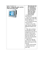
(4) Description of name plate
VER B 03
SOFTWARE
HARDWARE
VERSION
MODEL : AS 2 - 115 R
AS series
Voltage class :
1 : 110V
2 : 220V
4 : 380/440V
R : REMOTE CONTROL SERIES
H : HIGH SPEED SERIES
T : TIMING AND SPEED CONTROL SERIES
RP : REMOTE CONTROL AND PID
CONTROL SERIES
RT : REMOTE CONTROL AND SPEEDS
WITH TIMING CONTROL SERIES
Max Applicable motor(4 pole)
Single Phase :
104 : 0.4KW 107 : 0.75KW 115 : 1.5KW
122 : 2.2KW 137 : 3.7KW
3 Phase :
304 : 0.4KW 307 : 0.75KW 315 : 1.5KW
322 : 2.2KW 337 : 3.7KW
1
2. SPECIFICATIONS
(1) Single phase input port
Model
AS1
AS2
Voltage
1φ110VAC ±10%
1φ220VAC ±10%
Model No
AS1-104
AS1-107
AS2-104
AS2-107
AS2-115
AS2-122
Input Frequency
50HZ ~ 60HZ ± 10%
Output Voltage
3φ 220VAC
Output Frequency
0.5 ~ 400HZ / 0.5 ~ 2000HZ (High frequency)
AS2-137
Output
Rated current (A)
2.5 A
4.1 A
2.5 A
4.1 A
7A
10 A
16 A
Capacity (KVA)
1.0 KVA
1.6 KVA
1.0 KVA
1.6 KVA
2.7 KVA
3.8 KVA
6.1 KVA
Largest motor
KW ( 4 poles )
0.4KW
0.75KW
0.4KW
0.75KW
1.5KW
2.2KW
3.7KW
Control
Sine wave pulse width modulation
Braking
Regenerative discharge braking
Over current
Capacity
150% of rated current ( 1 minute)
Acceleration time
0.1 ~ 6000 SEC
Deceleration time
0.1 ~ 6000 SEC
Frequency Digital
setting
Analog
Use keyboard
for setting and confirm by
PROG
By frequency knob
Display type
LED Digits
Cooling Method
Self-cooled Air-cooled Self-cooled Self-cooled Air-cooled Air-cooled Air-cooled
Dimension drawing
Fig 1
Fig 2
Fig 1
Fig 1
Fig 2
Fig 2
Fig 3
Weight ( NW . KG )
1.2KG
1.3KG
1.2KG
1.3KG
1.3KG
1.4KG
4.2KG
Note : AS2-107 for special use, dimension drawing refer to Fig2.
2
(2) 3 Phase input port
Model
AS2
AS4
Voltage
3φ 220VAC ± 10%
3φ 380/440VAC ±10%
Model No
AS2-304
AS2-307
AS2-315
Input Frequency
AS2-322
AS2-337
AS4-307
AS4-315
AS4-322
AS4-337
50HZ ~ 60HZ ±10%
Output Voltage
3φ 220VAC
Output Frequency
3φ 380/440VAC
0.5 ~ 400HZ / 0.5 ~ 2000HZ (High frequency)
Output
Rated current (A)
3A
5A
8A
11 A
17 A
2.5 A
4A
6A
9A
Capacity (KVA)
1.1 KVA
1.9 KVA
3.1 KVA
4.2 KVA
6.5 KVA
1.9 KVA
3.1 KVA
4.2 KVA
6.9 KVA
Largest motor
KW ( 4 poles )
0.4 KW
0.75 KW
1.5 KW
2.2 KW
3.7 KW
0.75 KW
1.5 KW
2.2 KW
3.7 KW
Control
Sine wave pulse width modulation
Braking
Regenerative discharge braking
Over current
Capacity
150% of rated current ( 1 minute)
Acceleration time
0.1 ~ 6000 SEC
Deceleration time
0.1 ~ 6000 SEC
Frequency Digital
setting Analog
Use keyboard
for setting and confirm by
PROG
By frequency knob
Display type
LED Digits
Cooling Method
Self-cooled Self-cooled Air-cooled Air-cooled Air-cooled Air-cooled Air-cooled Air-cooled Air-cooled
Dimension drawing
Fig 1
Fig 1
Fig 2
Fig 2
Fig 3
Fig 2
Fig 2
Fig 2
Fig 3
Weight ( NW . KG )
1.2 KG
1.3 KG
1.3 KG
1.4 KG
4.2 KG
1.3 KG
1.3 KG
4.0 KG
4.0 KG
3
3. DIMENSION DRAWINGS
Unit : mm
Fig 1
4
Unit : mm
Fig 2
5
Unit : mm
Fig 3
6
4. INSTALLATION
Inadequate environment around installation site and installation
surface can result in damage to the inverter.
Before operating the AS series inverter, please check the following
points :
(1) Avoid high temperature, high humidity, easy-to-dew ambient environment. Don’t expose to dust or dirt, corrosive gas, and coolant
mist, and direct sunlight. Place the unit in a well-ventilated room.
(2) Avoid a place subjected to substantial vibration.
(3) When installing the unit within the cabinet. Please pay attention to
ventilation and limit the ambient temperature in between -10℃ ~
45℃ . (14℉ ~ 113℉ ).
(4) Use a nonflammable material, such a steel sheet on the wall for
installation. (The rear side will generate heat)
6 cm
6 cm
(5) Install the unit always vertically with a marginal spacing around.
5 cm
4 cm
5 cm
AIR FLOW
7
6 cm
6 cm
5 cm
4 cm
5 cm
AIR FLOW
2
1
8
5. DESCRIPTION OF TERMINALS
(1) Main circuit connection diagram
L1 L2 L3 U
V W
P PR
IM
GROUND
POWER
SOURCE
External braking resistor
Refer to the appendix A
MOTOR
Main circuit terminal
No.
Symbol
1
2
L1
3
L2
4
L3
5
U
6
V
7
W
8
P
9
Description
Terminal name
Ground
Ground(Earth) Terminal
Connect power supply
(L1,L2) Single Phase
(L1,L2,L3) 3 Phase
Inverter output
Terminals connected
to motor
Dynamic brake
Terminals connected to braking
Resistor, resistance refer to
Appendix A
PR
9
(2) Control circuit terminal
VCC FA1 FA2 GND C
1
2
3
4
5
A/B FWDREV CF1 CF2 FT1 FT2 MT
6
7
8
9 10 11 12 13
H COM
14 15
FM
Fault Relay
Contact rating
1A 240VAC
1A 30VDC
No
Symbol
Multi function analog terminal
1
VCC
Analog source
Power source +5V of analog terminals
2
FA1
Free analog terminal 1
See CD44 & 3-1 SW1
3
FA2
Free analog terminal 2
See CD45 & 3-1 SW1
4
GND
Analog common terminal
Common terminal of free analog terminals
Control circuit terminal
No
Symbol
Terminal name
Description
5
C
Alarm output C
Fault alarm contact (common)
6
A/B
Alarm output A/B
Fault alarm contact A(normal open) /
B(normal close)
7
FWD
Forward operation
Forward operation / stop terminal
8
REV
Reverse operation
Reverse operation / stop terminal
9
CF1
Multistage speed
terminal
10
CF2
CF1
CF2
SPEED
OFF
OFF
SPEED - 1
ON
OFF
SPEED - 2
OFF
ON
SPEED - 3
ON
ON
SPEED - 4
11
FT1
Multi function terminal 1
See functions description (CD42)
12
FT2
Multi function terminal 2
See functions description (CD43)
13
MT
14
H
Ref source +10V
Basic source +10V 20mA
15
COM
Common terminal
Common terminal of control terminals
Multi function output terminal (SEE 3-2 JP1)
10
(3) Description of Hardware setting
1
2
FT2
RST
MET
ARR
3
RUN
JP2
SW1
4
JP1
VCC FA1 FA2 GND C
A/B FWD REV CF1 CF2 FT1 FT2 MT
H COM
3-1 DIP Switch setting (SW1)
Setting FA1
ON
1
2
3
4
ON
1
2
3
FA1 : 0 - 10V
1
1
3
4
1
3
4
2
3
4
2
3
4
4
1
2
3
4
FA2 : 0 - 10V
FA2 : 0 - 5V
FA2 : 4 - 20mA
ON
Error setting
2
3
ON
FA1 : 4 - 20mA
2
2
ON
4
ON
1
ON
FA1 : 0 - 5V
ON
1
Setting FA2
Error setting
3-2 Jumper Setup
1.JP2 : ARR/MET/RUN/RST/FT2 terminal
MT : Multi function output terminal selector signal
ARR→ Frequency arrive in MT terminal.
MET→ Connecting a frequency Meter in MT terminal.
MT
RUN→ Running signal in MT terminal.
FT2 : Free Terminal 2 function selector
RST→ Reset system.
FT2
FT2 → Free terminal 2.
2.JP1 : Fault A/B
Fault A
Fault B
11
(4) WIRING
4-1 Wiring of main circuit
AS2-Series
THRY
MCCB
Filter
L1
U
L2
V
(L3)
W
IM
E
4-2 Wiring equipments
Select the wiring equipment and wiring size, refer to the table
below.
1. On the input power side, a molded case circuit breaker (MCCB)
to protect inverter primary wiring should be installed.
2. A leakage current breaker threshold of 200mA and above, or of
inverter use is recommended.
3. Use of input side magnetic contactor. An input MC can be used to
prevent an automatic restart after recovery from an external power
loss during remote control operation. However, do not use the MC
reduced reliability.
4. In general, magnetic contactors on the output of the inverter,
Should not be used for motor control. Starting a motor with the
inverter running will cause large surge currents and the inverter
overcurrent protector to trigger.
Model
AS1
AS2
AS4
Model No
04
07
04
07
15
22
37
07
15
22
37
Capacity (KVA)
1.0
1.6
1.0
1.6
2.7
3.8
6.1
1.9
3.1
4.2
6.5
Current
(A)
2.5
4.1
2.5
4.1
7
10
16
2.5
4
6
9
Circuit Breaker
(MCCB) (A)
15
15
10
10
15
20
20
10
10
10
15
Electro-Magnetic
Contactor (A)
12
12
12
12
12
12
18
12
12
12
12
Thermal relay
RC value (A)
4.8
7.6
2.4
3.8
6.8
9
15
1.9
3.4
3.8
6.8
12
4-3 Surge absorber
In order to prevent malfunction, provide the surge absorber on the
coils of the electromagnetic contactors, relays and other devices
which are to be used adjacent of the inverter.
4-4 Cable size and length
If the inverter is connected to a distant motor (especially when low
frequency is output), motor torque decreases because of voltage
drop in the cable. Use sufficiently heavy wire.
Changing the carrier frequency reduce RF1 noise and leakage
current. (Refere to the table below)
Distance
INVERTER → MOTOR
under
25M
under
50M
under
100M
above
100M
AS2 SERIES
under
16KHZ
under
10KHZ
under
5KHZ
under
2.5KHZ
4-5 EMI filter specifications
FREQUENCY (MHZ)
AS SERIES
Typical insertion loss (dB)
0.15
0.5
1
5
10
30
11
50
62
65
65
60
13
4-6 Wiring and cautionary points
A. Main circuit
1. Connect the cables of the power supply side to the U, V and W
output terminals for the motor.
2. Don’t connect any electromagnetic contactor between the
inverter and motor. If it is inevitable, turn on the contactor when
both the inverter and motor are both at stand still.
3. Don’t put the advance phase capacitor between the inverter and
motor.
4. Put MCCB in the input power supply.
B. Control signal circuit
1. Separate the power cables of main circuit etc. from the control
cables of the sequence and analog signals by passing the cables
through the different ducts.
2. Use twisted pair shielded wire for control signal and connect the
shield to earth terminal at on end, COMMON terminal of
control board. Leave the other end of shielding open.
3. Avoid common Ground leads between high and low level
voltage equipment.
C. Grounding
1. Be sure ground both the inverter and motor.
2. Keep grounded leads as short as possible.
3. Shield cables used to protect low-level signal leads should
grounded at one end point.
4. Provide class 3 grounding (100Ω or less) for a terminal.
5. When grounding several inverters, make connections as shown
below, no loop is produced as shown in FIG “a “ , FIG “b“ .
(a)
(b)
14
(c)
6. DIGITAL OPERATION PANEL
LED Operating Indication
Digital Indication
REV FWD
F 302
ADLEEPOWER
Key
LED Operating
Indication
FUNC
PROG
STOP
Digital Indication
FUNC
Key
PROG
STOP
R
Operation key
Key function
Description
FWD RUN
Forward run
Commands forward run
REV RUN
Reverse run
Commands reverse run
SHIFT
Cursor
movement
Select the digit
DOWN
Down
Decrease the parameter value
UP
Up
Increase the parameter value
PROG
PROG
Memory
storage
Saves the setting vaule
FUNC
FUNC
Function
Press once to select function CDxx and
press again to change its content
STOP
STOP
Stop
Stop operation / Escape to standby mode
15
7. FUNCTIONS DESCRIPTION
DISPLAY
ORDER
FUNCTION NAME
CD00
First speed setting
CD01
Parameter lock
0
CD02
Acceleration time 1
10 Sec
CD03
Deceleration time 1
10 Sec
CD04
Jogging frequency
5HZ
CD05
Start frequency
0.5HZ
CD06
Jog mode
0
CD07
Frequency meter correspond
CD08
CW or CCW or CW / CCW
0
CD09
Reserved
0
CD10
Keyboard / Analog signal from terminal
0
CD11
Dynamic brake / Free running
0
CD12
Terminal / Key board command
0
CD13
Reserved
CD14
Maximum frequency limit
CD15
Minimum frequency limit
☆
CD16
Frequency display Scale
☆
CD17
Maximum voltage frequency
☆
☆
☆
STANDARD
SETTING VALUE
U : 60HZ
E : 50(B03) / 0(B04)
U : 120 HZ
E : 100 HZ
U : 120 HZ
E : 50 HZ
0
U:1
E : 30
U : 60 HZ
E : 50 HZ
Different initial set value for E : European version and U : US version.
To change version see description of CD52.
16
CHANGEABLE
OF SETTING
VALUE
UNIT
0 ~ 400 HZ
0.01 HZ
0 or 1
----
0.1 ~ 6000 Sec
0.1 Sec
0.1 ~ 6000 Sec
0.1 Sec
0 ~ 400 HZ
0.01 HZ
0.5 ~ 30 HZ
0.01 HZ
0 or 1
----
30 ~ 400 HZ
0.01 HZ
0~2
----
0 = CW/CCW 1 = CW 2 = CCW
0 or 1
----
0 = Keyboard input 1 = Frequency knob
0 or 1
----
0 = Dynamic brake 1 = Free running
0 or 1
----
0 = Keyboard 1 = Terminal
0.5 ~ 400 HZ
0.01 HZ
0 ~ 400 HZ
0.01 HZ
0.01 ~ 500
0.01
25 ~ 400 HZ
0.01 HZ
USER
SETTING
REMARK
0 = lock 1 = Unlock
0 = Normal 1 = Jog
Display = Frequency × Scale
17
DISPLAY
ORDER
FUNCTION NAME
STANDARD
SETTING VALUE
CD18
V/F pattern setting
0
CD19
DC braking time
1 Sec
CD20
DC braking power
10
CD21
Torque boost
0%
CD22
Second speed setting
20 (B03) / 0 (B04)
CD23
Third speed setting
30 (B03) / 0 (B04)
CD24
Fourth speed setting
40 (B03) / 0 (B04)
CD25
Acceleration time 2
10 Sec
CD26
Deceleration time 2
10 Sec
CD27
Carrier frequency
16 KHZ
CD28
Output voltage gain
100 %
CD29
Frequency jump 1
0 HZ
CD30
Frequency jump 2
0 HZ
CD31
Freuqency jump 3
0 HZ
CD32
Jump range
0.5 HZ
CD33
Frequency reference bias
0
CD34
Frequency reference bias direction
0
CD35
Frequency gain
100.0 %
CD36
The latest error record
NONE
CD37
Errors record 1
NONE
18