Emcon with an APA 100
Bạn đang xem bản rút gọn của tài liệu. Xem và tải ngay bản đầy đủ của tài liệu tại đây (222.31 KB, 34 trang )
(0&21
(0&21ZLWKDQ$3$
$7($XJXVW
α
1
Copyright © 1999 by Gesellschaft für Verbrennungskraftmaschinen und
Meßtechnik mbH Prof.Dr.Dr.hc Hans List, Graz-Austria
Copyright 1999 by AVL List GmbH
The contents of this document may not be reproduced in any form or communicated to any third party
without the prior written consent of AVL. While every effort is made to ensure its correctness, AVL
assumes no responsibility for errors or omissions which may occur in this document.
Printed in Austria at AVL All rights reserved
(0&21ZLWKDQ$3$ &RQWHQWV
,
&RQWHQWV
'(6&5,37,21
*HQHUDO'HVFULSWLRQ
1.1.1 Validity ........................................................................................................................................................1
1.1.2 Purpose of EMCON.....................................................................................................................................1
1.1.3 System Overview .........................................................................................................................................2
7HFKQLFDO'DWD
'HYLFH'HVFULSWLRQ
1.3.1 General.........................................................................................................................................................3
1.3.2 Monitoring ...................................................................................................................................................4
1.3.3 Torque Measurement ...................................................................................................................................4
1.3.4 Speed Acquisition........................................................................................................................................5
1.3.5 Dyno Specific Keys on the Operating Panel ................................................................................................5
1.3.6 Parameters of the Dynamometer ..................................................................................................................7
78725,$/
([DPSOHVRI(YHU\GD\2SHUDWLRQ
2.1.1 Define/Change Parameters.........................................................................................................................11
2.1.2 Turn Dynamometer on ...............................................................................................................................13
2.1.3 APA-Speed Control Mode.........................................................................................................................13
2.1.4 Changing Rotation Sense ...........................................................................................................................14
2.1.5 Setting the Power-On Inhibition.................................................................................................................16
23(5$7,1*
$3$6SHHG&RQWURO0RGH
&RQWURO
/LPLWV
0$,17(1$1&(
6\VWHP&DUHDQG0DLQWHQDQFH
4.1.1 Care and Maintenance Intervals.................................................................................................................21
7URXEOHVKRRWLQJ
4.2.1 Disturbances during Operation...................................................................................................................21
3OXJ$VVLJQPHQW
4.3.1 Plug X2 when using an APA 100...............................................................................................................24
4.3.2 Plug X4 when using an APA 100...............................................................................................................25
4.3.3 Plug X5.3 when using an APA 100............................................................................................................26
4.3.4 Plug X5.5 when using an APA 100............................................................................................................26
4.3.5 Plug X7 when using an APA 100...............................................................................................................27
&RQWHQWV (0&21ZLWKDQ$3$
,,
4.3.6 Plug X8 when using an APA 100 ..............................................................................................................28
4.3.7 Plug X9 when using an APA 100 ..............................................................................................................29
4.3.8 Pins of Plug X23, Emergency Shutdown...................................................................................................30
4.3.9 Plug X24 when using an APA 100 ............................................................................................................31
(0&21ZLWKDQ$3$ 3UHIDFH
,,,
3UHIDFH
&RQWHQWVRIWKLV'RFXPHQWDWLRQ
This manual contains the description of the combination
(0&21ZLWKDWKUHHSKDVHDV\QFKURQRXVSHQGXOXPG\QR$3$IURP(/,1
for the operator.
The operator may only carry out those maintenance operations described in this manual.
All further maintenance tasks must only be carried out by trained service personal.
You will find further information in the following documents:
8VHUV*XLGH
&RQILJXUDWLRQ'HVFULSWLRQV
2SWLRQ'HVFULSWLRQV
3DUDPHWHULVDWLRQDQG2SHUDWLRQZLWK3&
6HUYLFHDQG,QVWDOODWLRQ
'\QRGHVFULSWLRQRIPDQXIDFWXUHU
DQGWKHVFKHPDWLFV
3UHIDFH (0&21ZLWKDQ$3$
,9
7\SRJUDSKLF&RQYHQWLRQV
6\PEROV8VHG
When you see the following symbol in this manual, they indicate the following:
This symbol in a box indicates important information!
This symbol in a box indicates additional information.
This symbol in a box indicates an example.
),*85(6
Figures are placed in boxes and provided with continuous numbers.
AvtÃ)ÃUr
The LEDs found upon the buttons of the EMCON 300’s operating panel are used to indicate certain states
and modes.
In order to depict the LEDs in this documentation the following symbols were chosen:
LED is off,
LED is blinking,
LED is on.
This finger over a particular button shows you which button should be pressed.
(0&21ZLWKDQ$3$ 3UHIDFH
9
If values can be adjusted by using the knobs on the operating panel, the following symbols indicate
which one to use.
Use left knob.
Use middle knob.
Use right knob.
3UHIDFH (0&21ZLWKDQ$3$
9,
This page intentionally left blank.
(0&21ZLWKDQ$3$ 'HVFULSWLRQ
'HVFULSWLRQ
*HQHUDO'HVFULSWLRQ
9DOLGLW\
The combination described in this manual consists of an EMCON and a three phase asynchronous
dynamometer (APA 100).
3XUSRVHRI(0&21
The EMCON with an asynchronous dynamometer is used as a device for measuring the effective power
of a unit under test (Otto-, Diesel-, Electric-engine or turbines). The asynchronous dynamometer is used
to acquire and control torque and speed. The APA 100’s construction and dimensions are designed
according to the unit under test.
EMCON communicates with the asynchronous dynamometer via a fieldbus connection. The fieldbus
transmits
• states (errors, switch positions)
• commands (dyno on, dyno off)
• actual values (speed, torque)
• demand values (speed, torque)
as digital signals.
The pendulum torque signal necessary for controlling the torque is measured directly at the
dynamometer. The load cell is directly connected to the EMCON.
If the test bed’s dynamometer is replaced, the load cell has to be re-calibrated. Otherwise
measurement errors may occur.
EMCON provides various signals to control the test sequence (auxiliary devices ON/OFF, control modes,
preheating etc.).
'HVFULSWLRQ (0&21ZLWKDQ$3$
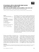
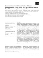
6\VWHP2YHUYLHZ
The minimum power test equipment consists of:
• one EMCON
• one asynchronous pendulum dynamometer with mounting
• power control unit
It can be completed by various additional devices.
(0&21
possible
options
supplied by
customer
Testbed Computer
unit under test
throttle
actuator
Watch-Dog-Module
minimum
extent
External
Operating Panel
EMCON
Strip 1
engine
monitor
signals
APA 100 power output stage
pendulum torque
Fieldbus
Avtà )ÃTrÃPrvr
(0&21ZLWKDQ$3$ 'HVFULSWLRQ
7HFKQLFDO'DWD
The technical data of the various system components can be found in the relevant documentation.
'HYLFH'HVFULSWLRQ
*HQHUDO
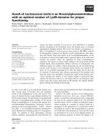
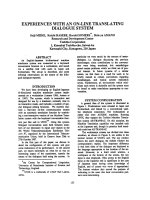
The asynchronous pendulum dynamometer acquires and controls speed and torque. The generalized
power diagram shows the limits of the dynamometer.
The APA 100 can also be used to start the engine.
n
T
o.
P
nominal power
maximum power
nominal torque
maximum torque
the maximum values are valid for
max. 1 min. with 15 min. cool down
AvtÃ!)ÃQrÃ9vhthÃsÃhÃ6Q6Ã Ãtrrhy
The power diagram of the dyno in use can be found in the dyno documentation.
'HVFULSWLRQ (0&21ZLWKDQ$3$
0RQLWRULQJ
The monitored signals are configuration dependent. Exact information can be found in
the documentation of the manufacturer.
The asynchronous pendulum dynamometer is monitored by the APA 100’s power control unit. Apart
from acquiring and evaluating the actual values of torque (X8) and speed (X7) the limits are continuously
monitored. The power is monitored by the APA power control unit.
If the engine monitor is used the signals of the unit under test can be connected to plug X9 and X24
where EMCON outputs the Ignition On and other signals!
Malfunctions are signaled audibly and generate error messages and partially interrupt the test or stop the
test from being started.
If one of the definable monitoring values is violated, an alarm text is displayed and the system is stopped.
The communication with the APA 100’s power control unit via the fieldbus interface is cyclically
monitored.
7RUTXH0HDVXUHPHQW
The torque measuring system consists of a torque load measuring unit and the measured value processing
and digital display within EMCON.
In the torque load measuring unit a "load cell" is used as load detector. The load implied by the dynos
lever is measured with strain gauges. The high spring tension of this torque load measurement is a big
advantage.
When measuring with the load cell you should pay attention to the following
• stay within the defined temperature range.
• don’t change the temperature faster than 5 K/h.
• avoid direct radiant heat on the load cell; if necessary use a shield.
• the load cell must be grounded to the base plate with a flexible cable.
EMCON can also process a ±10 V signal to acquire the torque value.
(0&21ZLWKDQ$3$ 'HVFULSWLRQ
6SHHG$FTXLVLWLRQ
The APA 100 generally uses optical sensors (Heidenheim speed impulse sensors).
The number of lines depends on the maximum speed (10 000 rpm = 1024 lines).
The speed signal can be connected to the EMCON either via a signal splitter or directly. EMCON
provides two speed values; that which is directly measured and the one transmitted via the fieldbus. The
signals are continuously compared. If they differ, the system is stopped.
'\QR6SHFLILF.H\VRQWKH2SHUDWLQJ3DQHO
The dyno independent keys are described in the User’s Guide.
*URXS'\QR
%XWWRQ 1DPH )XQFWLRQ ,OOXPLQDWHG/('PHDQV
APA
ON/OFF
APA ON/OFF Turn the power output stage on
and off.
Power output stage is on.
Blinking means the power output
stage is being turned on.
APA-SPEED Speed control of dyno only. Control mode is active.
APA Fan Turn APA ventilation fans on
and off.
The ventilation fans are on.
(Default after turning the APA
on)
The APA 100’s ventilation fans must stay on during operation. They only may be turned
off for a short time.
The ventilation fans are automatically turned on again if the winding temperature
becomes too high.