Tài liệu biến tần danfoss FC 300
Bạn đang xem bản rút gọn của tài liệu. Xem và tải ngay bản đầy đủ của tài liệu tại đây (1.58 MB, 68 trang )
FC 300 Instruction Manual
Contents
! How to Read this Instruction Manual 3
" Approvals 4
" Symbols 5
" Abbreviations 5
! Safety Instructions and General Warning 7
" Disposal Instructions 7
" Software Version 7
" High voltage warning 8
" Safety Instructions 8
" High start torque 8
" Safe Stop of FC 302 9
" IT Line 9
! How to Install 11
" How to Get Started 11
" Accessory Bag ≤ 10 HP [7.5 kW] 12
" Mechanical Installation 14
" Electrical Installation 15
" Removal of Knockouts for Extra Cables 15
" Connection to Line Supply and Grounding 15
" Motor Connection 18
" Motor cables 20
" Fuses 21
" Access to Control Terminals 23
" Electrical Installation, Control Terminals 23
" Basic Wiring Example 24
" Connection Examples 25
" Start/Stop 25
" Pulse start/stop 25
" Speed up/slow down 26
" Potentiometer Reference 26
" Electrical Installation, Control Cables 27
" Switches S201, S202, and S801 28
" Tightening Torque 28
" Final Set-Up and Test 29
" Additional Connections 31
" Control of Mechanical Brake 31
" Motor Thermal Protection 31
! How to Program 33
" Quick Setup 34
" Parameter lists 37
" Parameter Selection 38
! General Specifications 53
1
MG.33.A6.22 - VLT is a registered Danfoss trademark
FC 300 Instruction Manual
! Warnings and Alarms 59
" Warnings/Alarm Messages 59
! Index 67
2
MG.33.A6.22 - VLT is a registered Danfoss trademark
FC 300 Instruction Manual
How to Read this Instruction Manual
" How to Read this Instruction M anual
This Instruction Manual will help you get star ted , install, program, and troubleshoot
your VLT
®
AutomationDrive FC 300.
The FC 300 comes in two shaft performance levels. F
C 301 ranges from scalar (U/f) to VVC+,
and FC 302 ranges from scalar (U/f) to servo performance.
ThisInstructionManualcoversbothFC301andFC302. Whereinformationcoversbothseries,we
refer to FC 300. Otherwise, we refer specifical
ly to either FC 301 or FC 302.
Chapter 1, How to Read this Instruction
Manual, introduces the manual and informs you
about the approvals, symbols, a n d abbr
eviations
used in this literature.
Page divider for How to Read this Instruction Manual.
Chapter 2, Safety Instructions and Gen eral
Warnings,entail
s instructions on how to
handle the FC 300 correctly.
Page divider for
Safety Instructions and General Warnings.
C
hapter 3, How to Install , guides you through
mechanical and technical installation.
Page divider for How to Install
3
MG.33.A6.22 - VLT is a registered Danfoss trademark
FC 300 Instruction Manual
How to Read this Instruction Manual
Chapter 4, How to Program,showsyou
how to operate and program the FC 300 via
the Local Control Panel.
Page divider for How to Program.
Chapter 5, General Specifications, entails
technical data about FC 300.
Page divider for General Sp ecifications.
Chapter 6, Troubleshooting, assists you in solving
problems that may occur when using FC 300
.
Page divider for Troubleshooti
ng.
Available
literature for FC 3 00
- The VLT
®
AutomationDrive FC 300 Instruction Manual provides the necessary infor-
mation for getting the drive up and running.
- The VLT
®
AutomationDrive FC 300 Design Guide entails all technical information about
the d rive and customer design and ap plications.
- The VLT
®
AutomationDrive FC 300 Profibus Operating Instructions (Instruction Manua l) provide the
information required for controlling, monitoring, and programming the drive via a Profibus fieldbus.
- The VLT
®
AutomationDrive FC 300 DeviceNet Operating Instructions (Instruction Ma nual) provide the
information required for controlling, monitoring, and programming the drive via a DeviceNet field bus.
- The VLT
®
AutomationDrive FC 300 MCT 10 Operating Instructions (Instruction Manual) provide
information for installation and use of the software on a PC.
- The VLT
®
AutomationDrive F C 300 I P21 / TYPE 1 Instruction provides information
for installing the IP21 / TYPE 1 option.
- The VLT
®
AutomationDrive FC 300 24 V DC Backup Instruction provides information
for installing the 24 V DC Backup option.
Danfoss Drives te chnical literature is also available online at www.danfoss.com/drives.
" Approvals
4
MG.33.A6.22 - VLT is a registered Danfoss trademark
FC 300 Instruction Manual
How to Read this Instruction Manual
" Symbols
Symbols used in these Operating Instructions.
NOTE
Indicates something to be noted
by the reader
Indicates a general warning.
Indicates a hi gh voltage warning
Indicates default setting
" Abbreviations
Alternating current AC
American wire gauge AWG
Ampere/AMP A
Automatic Motor Adaptation AMA
Current limit I
LIM
Degrees Celsius °C
Direct current DC
Drive D ependent D-TYPE
Electro Magnetic Compellability EMC
Electronic Thermal Relay ETR
Adjustable Frequency Drive AFD
Gram g
Hertz Hz
Kilohertz kHz
Local Control Panel LCP
Meter m
Milli Henry Inductance mH
Milliampere mA
Millisecond, Second ms, s
Minute min
Motion Control Tool MCT
Motor Type Dependent M-TYPE
Nanofarad nF
Newton meter Nm
Nominal motor current I
M,N
Nominal motor frequency f
M,N
Nominal motor power P
M,N
Nominal motor voltage U
M,N
Parameter par.
Protective Extra Low Voltage PELV
Printed Circuit Board PCB
Rated Inverter Output Current I
INV
Revolutions per minute RPM
Second s
Tor qu e limit T
LIM
Volt V
5
MG.33.A6.22 - VLT is a registered Danfoss trademark
FC 300 Instruction Manual
How to Read this Instruction Manual
6
MG.33.A6.22 - VLT is a registered Danfoss trademark
FC 300 Instruction Manual
Safety Instructions and General Warning
Equipment containing electrical components may no
tbedisposed
together with domestic waste.
It must be collected separately as electrical and electronic waste
according to local and curren tly valid legislatio
n.
Caution
The FC 300 AutomationDrive DC link capacitors remain c harged after power has been
disconnected. To avoid an electrica l shock hazard, disco nn ect the FC 300 from th e power
supply before carrying ou
tmaintenance. Waitatleastaslongasfollowsbeforeservicingthe
adjustable frequency drive:
FC 300: 0.34 – 10 HP
[0.25–7.5
kW]
4minutes
FC 300: 14.75 – 29.5
HP [11 – 22
kW]
15 minutes
BeawarethattheremaybehighvoltageontheDClinkevenwhentheLEDsareturnedoff.
7
MG.33.A6.22 - VLT is a registered Danfoss trademark
FC 300 Instruction Manual
Safety Instructions and General Warning
FC 300
Instruction Manual
Software version: 3.5x
This instruction manu al can be used for all FC 300 Series adjustable frequency drives (AFD)
with software version 3.5x.
Thesoftwareversionnumbercanbeseenfromparameter15-43.
" High voltage warning
The voltage of the FC 300 is dangerous whenever the converter is connected to electrical
power. Incorrectfittingofthemotororadjustablefrequencydrivemaycausedamageto
the equipment, serious injury or death. Consequently, it is essential to c omply w ith the
instructions in this manual as well as local and national rules and safety regulations.
" Safety Instr uc tion s
• Make sure the FC 300 is properly conne cted to ground.
• Do not remove mains plugs or motor plugs while the FC 300 is connected to mains.
• Protect users against supply voltage.
• Protect the motor against overloading according to national and local regulations.
• Motor overload protection is not included in the default settings. To ad d this function, set parameter
1-90 Motor thermal protection to value ETR trip or ETR warning . For the North American market:
ETR functions provide class 20 motor overload protection, in accordance with NEC.
• The ground leakage current exceeds 3.5 mA.
• The [OFF] key is not a safety switch. It d oes not disconnect the FC 300 from mains.
" Before Commencing Repair Work
1. Disconnect FC 3 00 from AC line.
2. Disconnect DC bus terminals 88 and 89
3. Wait at least 15 minutes
4. Remove motor cable
" High start torque
While FC 300 is connected to AC line, the motor can be started/stopped using digital
commands, bus commands, references or a loca l stop.
• Disconnect the FC 300 from AC line w hene ver pe rsonal safety considerations make
it necessary to avoid unintended start.
• To avoid unintended s tart, always activate the [OFF] key before changing parameters.
• Unless terminal 37 is turned off, an electronic fault, temporary overload, a fa ul t in the AC line
supply, or lost motor connection may cause a stopped motor to start.
8
MG.33.A6.22 - VLT is a registered Danfoss trademark
FC 300 Instruction Manual
Safety Instructions and General Warning
" Safe Stop of FC 302
The FC 302 can perform the Designated Safety Function Uncontrolled Stopping by removal of power. (as
defined by draft IEC 61800-5-2) or Stop Category 0 (as defined in EN 60204-1). It is designed and approved
suitable for the requireme n ts of Safety Category 3 in EN 954-1. This functionality is called Safe Stop.
In order to install and use the Safe Stop f unction in accordance with the require m ents of Safety
Category 3 in EN 954-1, the related information and instructions of the FC 300 Design Guide
MG.33.BX.YY must be f ollowed! The information and instructions of the Instructio n Manual are
not sufficient for a correct and safe use of the Safe Stop functionality!
General warning
Warning:
Touching the electrical parts may be fatal - even after the equipment has been
disconnected from the power supply.
Also make sure that other voltage inputs have been disconnected, such as load-sharing (linkage
of DC int ermediate circuit), as well as t he motor connection for kinetic backup.
Using VLT AutomationDrive FC 300: wait at least 15 minutes.
A shorter time is allowed only if indicate d on the nameplate for the specific unit.
Leakage Current
The ground leakage current from the FC 300 exceeds 3.5 mA. To en
sure that the ground c able
has a good mechanical connection to the ground connection (terminal 95), the cable cross-section
must be at least 3.9 in2 [10 mm2] or have 2 rated ground wires terminated separately.
Residual Current Device
This product can cause DC current in the prote ctive conductor. If a residual cur rent device (RCD)
is used for extra protection, only an RCD of Type B (time de layed) may be used on the supply
side of this product. See also RCD Application Note
MN.90.GX.02.
Protective grounding of the FC 300 and the use of RCDs must always follow national and loca l regulations.
IT Line
Do not connect 400 V adjustable frequency dri
ves with RFI filters to line power supplies
with a voltage between phase and ground of mo re than 440 V.
For IT line and delta ground (grounded leg), line voltag e may exceed
440 V between phase and ground.
Par. 14-50 RFI 1 can be used on the FC 302 to disconnect the internal RFI capacitors from the RFI
filter to ground. If this is done, it will reduce the RFI p erform ance to A2 level.
9
MG.33.A6.22 - VLT is a registered Danfoss trademark
FC 300 Instruction Manual
Safety Instructions and General Warning
10
MG.33.A6.22 - VLT is a registered Danfoss trademark
FC 300 Instruction Manual
How to Install
" About H ow to Install
This chapter covers mechanical and e lectrical installations to and from power
terminals and control card terminals.
Electrical installation of options is described
in the corresponding "Option Guide".
" How to Get Started
You can carry out a quick and EMC-correct
installation of the FC 300 by following the
steps described below.
Read the safety instructions be fore
installing the unit.
Diagram showing basic installation including,
electrical connection, motor, start/stop key, and
potentiometer for speed adjustment.
11
MG.33.A6.22 - VLT is a registered Danfoss trademark
FC 300 Instruction Manual
How to Install
" Accessory Bag ≤ 10 HP [7.5 kW]
The following parts are included in the FC
300 Accessory Bag.
1 + 2 only available in units with brake chopper.
There is only one relay connector for the FC
301. (≤ 10 HP [7.5 kW])
For the DC link connection (load sharing), connector 1 can
be ordered separately (order number 130B1064).
12
MG.33.A6.22 - VLT is a registered Danfoss trademark
FC 300 Instruction Manual
How to Install
Accessory Bag ≤ 10 HP [7.5 kW], IP 55
1 + 2 only available in units with brake chopper.
There is only one relay connector for the FC 301.
(≤ 10 HP [7.5 kW], IP55)
Accessory Bag 14.75 -2 9.5 HP [11-22 kW]
There is only one relay connector for the FC 301.
(14.75-29.5 HP [11-22 kW])
13
MG.33.A6.22 - VLT is a registered Danfoss trademark
FC 300 Instruction Manual
How to Install
" Mechanical Installation
" Mechanical Mounting
1. Drill holes in accord ance with the measurements given.
2. Yo u must provide screws suitable for the surface on which you want to mount
the FC 300. Retighten all four screws.
FC 30 0 IP20 allows side-by-side i ns tallation. Because of the need for cooling, there must be a
minimum of 4 in (100 mm) free air passage above and below the FC 300.
The back wall must always be solid.
14
MG.33.A6.22 - VLT is a registered Danfoss trademark
FC 300 Instruction Manual
How to Install
" Electrical Installation
NOTE
Cables General
Always comply with national and local regulations on cable cross-sections.
Tightening-up Torque
AFD size Cable for: Tightening-up torque
0.34-10 HP [0.25-7.5
kW]
Line, brake resistor, load sharing motor
cable
0.5-0.6 Nm
1.8 Nm
14.75-10 HP [1 1-15
kW]
Line, brake resistor, load sharing motor
cable
1.8 Nm
14.75-10 HP [1 1-15
kW]
Motor cable 1.8 Nm
Relay 0.5-0.6 Nm
Ground 2-3 Nm
" RemovalofKnockoutsforExtraCables
1. Remove the cable entry from the adjustable frequency dri ve (avoid foreign parts entering
the adjustable frequency drive when removing knockouts).
2. The cable entry must be supported around the knockout you intend to remove.
3. The knockout can now be removed with a strong mandrel and a hammer.
4. Remove burrs from the hole.
5. Mount cable entry on adjustable frequency drive.
" Connection to Line Supply and Grounding
NOTE
The plug connec tor for power can
be removed.
1. Make sure the FC 300 is properly grounded.
Connect to ground connection (terminal 95).
Use screw from the accessory bag.
2. Place plug connector 91, 92, 93 from the
accessory bag onto the terminals labeled
MAINS at the bo ttom of the FC 300.
3. Connect line wires to the line plug connector.
The ground connection cable cross-section
must be at least 3.9 in
2
[10 mm
2
]or
have 2 rated line supply wires terminated
separately according to EN 50178.
The line supply connection is fitted to the line
supply switch if this is included.
15
MG.33.A6.22 - VLT is a registered Danfoss trademark
FC 300 Instruction Manual
How to Install
How to connect to the line supply and grounding
(A2 and A3 enclosure).
How to connect to the line supply and ground-
ing (A5 enclosure).
Howtoconnecttothelinesupplyandgrounding
(B1 and B2 enclosure).
NOTE
Check that AC line voltage corresponds to
the line voltage of the FC 300 nameplate.
IT Line
Do not conne
ct 400 V adjustable
frequency d rives with RFI filters to line
supplies with a voltage between phase
and grou
nd of more than 440 V.
For IT lines and delta ground (grounded leg),
line voltage may exceed 440 V betw een
phase a
nd ground.
Terminals for line supply a nd grounding.
16
MG.33.A6.22 - VLT is a registered Danfoss trademark
FC 300 Instruction Manual
How to Install
How to connect to the line supply and grounding
with disconnector (A5 enclosure).
17
MG.33.A6.22 - VLT is a registered Danfoss trademark
FC 300 Instruction Manual
How to Install
" Motor Connection
NOTE
Motor cable must be shielded/armored. If
an unshielded/unarmored cable is used,
some EMC requirements are not complied
with. For more information, see EMC specifications
in the VLT AutomationDrive FC 300 Design Guide.
1. Fasten decoupling plate to the bottom
of the FC 300 with screws and washers
from the accessory bag.
2. Attach motor cable to terminal s 96 (U),
97 (V ), 98 (W).
3. Connect to ground connection (terminal
99) on decoupling p late with screws from
the accessory bag.
4. Insert plug connectors 96 (U), 97 (V), 98 (W)
and motor cable into terminals labele d MOTOR.
5. Fasten shielded cable to decoupling plate with
screws and washers from the accessory b ag.
18
MG.33.A6.22 - VLT is a registered Danfoss trademark
FC 300 Instruction Manual
How to Install
Motor connection ≤ 10 HP [7.5 kW] IP 20 (A2
and A3 enclosures)
Motor connection ≤ 10 HP [7.5 kW] IP 55 / NEMA type 12
Motor connection 14.75-29.5 HP [11-22 kW] IP 21
/ NEMA type 1 (B1 and B2 enclosures)
19
MG.33.A6.22 - VLT is a registered Danfoss trademark
FC 300 Instruction Manual
How to Install
No. 96 97 98 Motor voltage 0-100%
U V W of AC line voltage.
3 wires out of motor
U1 V1 W1
W2 U2 V2
6 wires out of motor, Delta-connected
U1 V1 W1 6 wires out of motor, Star-connected
U2, V2, W2 to be interconnected separately
No. 99 Ground connection
PE
All types of three-phase asynchronous standard
motors can be connected to the FC 300. Normally,
small m otors are star-connecte d (230/400 V,
/Y). Large motors are normally delta-connecte d
(400/690 V,
/Y). Refer to the motor nameplate
for corre ct connection mode and voltage.
NOTE
In m otors without phase insulation paper or other insulation reinforcement suitable for operation
with voltage supply (such as adjustable frequency drive), fit an LC filter on the output of the FC 300 .
" Motor cables
See Technical data for correct sizing of motor cable cross-section and length. Always comply
with national and local regulations on cable cross-section.
• Use a shielded/arm oured motor cable to comply with EMC emission specifications
unless otherwise stated for the RFI filter used.
• Keep the motor cable as short as possible to reduce the noise level and leakage currents.
• Connect the motor cable shield to the decoupling plate of the FC 300 and to the metal cabinet of the motor.
• Make the shield connections with the largest possib le surface area (cable clamp). This is
done by using the supplied installation devices in the FC 300.
• Avoid mounting with twisted screen end s (pigtails), which will spoil high frequency screening effects.
• If it is necessary to split the shield to install a motor isolator or motor relay, the shield
must be continued with the lowest possible HF impe dance .
20
MG.33.A6.22 - VLT is a registered Danfoss trademark
FC 300 Instruction Manual
How to Install
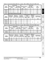
" Fuses
Branch circuit protection:
In order to protect the install ation against electrical and fire hazard, all branch circuits
in an installation, sw itch gear, machines, etc., must be short-circuit and overcurrent-
protected accord ing to national/international regulations.
Short circuit protection:
The adjustable frequency drive must be protected against short-circuit to avoid e lectrical or fire
hazard. Danfoss recommends using the fuses mentioned below to protect service personne l or
other equipment in case of an internal failure in t h e drive. The adjustable frequency drive provides
full short-circuit protection in case of a short-circuit on the motor output.
Overcurrent protection:
Provide overload protection to avoid fire hazard due to overheating of the cable s in the instal
lation.
The adjustable frequency drive is equip ped with internal overcurrent protect ion that can be used
for upstream overload protection (UL applications excluded). See par. 4-18. Moreover, fuses
or circuit breakers can be used to provide overcurrent protection in the installation. Ov
ercurrent
protection must always be provided according to national regulations.
Fuses must be designed for protection in a c ircuit capable of supplying a maximum of
100,000 A
rms
(symmetrical), 500 V maximum.
Non-UL compliance
If UL/cU L is not to be complied with, we
recommend using the following fuses
, which will
ensure compliance w ith EN50178:
In case of malfunction, not following the
recommendation may result in unnec
essary damage
to the adjustable frequency drive.
FC 30X Max. fuse size Voltage Type
K25-K75 10A
1)
200-240 V type gG
1K1-2K2 20A
1)
200-240 V type gG
3K0-3K7 32A
1)
200-240 V type gG
K37-1K5 10A
1)
380-500 V type gG
2K2-4K0 20A
1)
380-500 V type gG
5K5-7K5 32A
1)
380-500 V type gG
11K 63A
1)
380-500 V type gG
15K 63A
1)
380-500 V type gG
18K 63A
1)
380-500 V type gG
22K 80A
1)
380-500 V type gG
1) Max. fuses - se e n ational/inte rnational
regulations for selecting an applicable fuse size.
21
MG.33.A6.22 - VLT is a registered Danfoss trademark
FC 300 Instruction Manual
How to Install
UL Compliance
200-240 V
FC 30X Bussmann Bussm ann Bussmann SIBA L it tel fuse
Ferraz-
Shawmut
Ferraz-
Shawmut
kW Type RK1 Type J Type T Type RK1 Type RK1 Type C C Type RK1
2-7.5 KTN-R10 JKS-10 JJN-10 5017906-010 KLN-R10 ATM-R10 A2K-10R
1.1-2.2 KTN-R20 JKS-20 JJN-20 5017906-020 KLN-R20 ATM-R20 A2K-20R
3.0-3.7 KTN-R30 JKS-30 JJN-30 5012406-032 KLN-R30 ATM-R30 A2K-30R
380-500 V, 525-600 V
FC 30X Bussmann Bussmann Bussmann SIBA Littel fuse
Ferraz-
Shawmut
Ferraz-
Shawmut
kW Type RK1 Type J Type T Type RK1 Type RK1 Type CC Type RK1
0.37-1.5 KTS-R10 JKS-10 JJS-10 5017906-010 KLS-R10 ATM-R10 A6K-10R
2.2-4.0 KTS-R20 JKS-20 JJS-20 5017906-020 KLS-R20 ATM-R20 A6K-20R
5.5-7.5 KTS-R30 JKS-30 JJS-30 5012406-032 KLS-R30 ATM-R30 A6K-30R
11.0 KTS-R40 JKS-40 JJS-40 5014006-040 KLS-R40 A6K-40R
15.0 KTS-R50 JKS-50 JJS-50 5014006-050 KLS-R50 A6K-50R
18.0 KTS-R60 JKS-60 JJS-60 5014006-063 KLS-R60 A6K-60R
22.0 KTS-R80 JKS-80 JJS-80 5014006-100 KLS-R80 A6K-80R
KTS fuses from Bu
ssmann may substitute KTN for 240 V adjustable frequency drives.
FWH fuse s from Bussmann may substitute FW X for 240 V adjustable frequency drives.
KLSR fuses from LITTEL FUSE may substitute KLNR fuses for 240 V ad justable frequency drives.
L50S fuses from LITT
EL FUSE may substitute L50S fuses for 240 V adjustable frequency drives.
A6KR fuses from FERRAZ SHAWMUT may substitute A2KR for 240 V adjustable frequency drives.
A50X fuses from FERRAZ SHAWMUT may substitute A25X for 240 V adjustable frequency drives.
22
MG.33.A6.22 - VLT is a registered Danfoss trademark
FC 300 Instruction Manual
How to Install
" Access to Control Terminals
All terminals to the control cables are located
underneath the terminal cover on the front of the
adjustable frequency drive. Remove the terminal
cover by means of a screwdriver (see illustration).
A1, A2 and A3 enclosures
A5, B1 and B2 en closures
"
Electrical Installation, Control Terminals
To mount the cable to the terminal:
1. Strip isolation of 0.34-0.39 in [9-10 mm]
2. Insert a screwdrive
r in the square hole.
3. Insert the cab le in the adjacent circular hole.
4. Remove the screwdriver. The cable is now
mounted to the term
inal.
To remove the cable from the terminal:
1. Insert a screwdriver in the square hole.
2. Pull out the cable.
1. 2.
3.
23
MG.33.A6.22 - VLT is a registered Danfoss trademark
FC 300 Instruction Manual
How to Install
Assembling IP 55 / NEMA TYPE 12 (A5 housing)
with line supply disconnector
" Basic Wiring Example
1. Mount terminals from the accessory bag
to the front of the FC 300.
2. Connect terminals 18
, 27 and 37 (FC 302
only) to +24 V (terminal 12/13)
Default settings:
18 = start
27 = coast inverse
37 = safe stop inverse
24
MG.33.A6.22 - VLT is a registered Danfoss trademark
FC 300 Instruction Manual
How to Install
" Connection Examples
" Start/Stop
Terminal 18 = start/stop par. 5-10 [8] Start
Terminal 27 = No o peration par. 5-12 [0] No
operation (Default coast inverse
Terminal 37 = Safe sto p (FC 302 o nly)
Par. 5-10 Digital Input = Start (default)
Par. 5-12 Digital Input = coast inverse (default)
" Pulse start/stop
Terminal 18 = start stop/ par. 5-10 [9] Latched start
Terminal 27= Stop par. 5-12 [6] Stop inverse
Terminal 37 = Safe sto p (FC 302 o nly)
Par. 5 Digital input = Latched start
Par. 5 Digital input = Stop inverse
25
MG.33.A6.22 - VLT is a registered Danfoss trademark