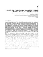
on decoupled parallel manipulators
Bạn đang xem bản rút gọn của tài liệu. Xem và tải ngay bản đầy đủ của tài liệu tại đây (423.1 KB, 13 trang )
Hội nghị toàn quốc về Điều khiển và Tự động hoá - VCCA-2011
VCCA-2011 I-3
On Decoupled Parallel Manipulators
Victor Glazunov
Mechanical Engineering Research Institute, Russian Academy of Sciences,
121354, Kutuzov st. 2, ap. 402, Moscow, Russia,
ph. +(495) 624-00-28, +(495) 446-30-07, e-mail:
Abstract. Decoupled parallel manipulators with
three parallel kinematic chains are considered. The
synthesis of these mechanisms is carried out by means
of screw groups. This approach allows avoiding
completed equations by synthesis and singularity
analysis of these mechanisms.
Keywords: parallel manipulator, decoupled
mechanism, the theory of screws, twist, wrench,
singularities, screw groups.
1. Introduction
It is well-known that the closed-loops of parallel
manipulators cause high stiffness and payload capacity
[1-7]. However, due to the coupling between kinematic
chains, control of the motions of the moving platform
becomes complicated. There exist different solutions of
this problem [2-5]. One of them is to arrange for
coincidence of centers of the spherical kinematic pairs
of three identical kinematic chains S-P-S of the Gough-
Stewart platform [8, 9]. Another solution corresponds
to the special architecture of the U-P-U kinematic
chains of a 6 degrees of freedom (6-DOF) parallel
manipulator in which three U-joints mounted on the
moving platform (end-effector) are designed as a
spherical mechanism [10-12]. However, these solutions
do not allow the retention of constant orientation of the
moving platform when only the actuators
corresponding to translation motion are driven.
Another approach to a solution of this problem is
applicable for a parallel manipulator with reduced
degrees of freedom. For example, the well known
Delta robot consists of three R-R-P-R kinematic
chains (the P-pair is designed as a four-bar planar
parallelogram) causing translation motions of the
moving platform and of one R-U-P-U kinematic
chain, causing rotation about the vertical axis [13].
This robot corresponds to Schoenflies motions
besides, in this robot, three translation motions and
one rotation motion are decoupled. Another well
known robot with Shoenflies motions of the platform
is PAMINSA [14]. In this manipulator one vertical
motion is decoupled from the three planar motions.
Note that the translation kinematic pairs can be
represented as planar four-bar parallelograms [10-13,
15-17]. By this approach numerous families of
decoupled and translation parallel mechanisms are
obtained [15-17].
A 6-DOF manipulator with decoupled translation and
rotation motions and with linear and rotating actuators
situated on the base is synthesized by means of
geometrical constraints [18-20]. This manipulator
consists of three kinematic R-P-P-P-R-R chains and
allows retention of a constant orientation of the
moving platform when only the linear actuators
corresponding to the translation motion are driven.
In this paper, we use the approach to synthesis of
decoupled parallel manipulators based on closed
screw groups [21, 22] that include all the screw
products of the main members of these groups. These
groups describe motions of non-overconstrained
mechanisms. Similar screw groups are considered
from different viewpoints [23-26]. A new decoupled
6-DOF parallel manipulator is proposed which
consists of three kinematic R-P-P-P-R-R chains where
the P-pairs are represented as four-bar planar
parallelograms. This allows transferring of rotations
without sliding. Besides decoupled manipulators with
three DOF, four DOF and six DOF are obtained.
With regard to the determination of the singularity the
Jacobian matrices relating the input speeds to the
output speeds can be applied [27]. Using this
approach one needs to differentiate equations
expressing the constraints imposed by kinematic
chains. Therefore in this paper we use the screw
groups approach to describe singularities [28-30]
which allows avoidance of complicated mathematical
equations. As the screw groups can be obtained
without complicated equations the style of the article
can be chosen like a textbook on the subject.
2. Description of closed screw groups
Let us consider the closed screw groups [21, 22]
corresponding to planar, spherical, and spatial
mechanisms. These groups include all the screw
products of their main members. Without loss of
generality we can use the simplest representation of the
main screws (twists) of these groups by Plücker
coordinates. Besides which, we consider only 1-DOF
kinematic pairs.
The closed screw groups are:
one-member screw group which can be
represented by Plücker coordinates
1
(1, 0, 0, 0,
0, 0) or
1
(1, 0, 0, p, 0, 0) or
1
(0, 0, 0, 1, 0, 0).
This group corresponds to one 1-DOF kinematic
pair, rotation, screw, or prismatic. Here, p is the
pitch.
Hội nghị toàn quốc về Điều khiển và Tự động hoá - VCCA-2011
VCCA-2011 I-4
two-member screw group which can be
represented by Plücker coordinates of the main
members
1
(1, 0, 0, p, 0, 0) and
2
(0, 0, 0, 1, 0,
0), where p is the pitch. This group corresponds to
two 1-DOF kinematic pairs (one of them can be
prismatic) whose axes are situated along the same
line, this expresses motions along and around one
axis.
two-member screw group which can be
represented by Plücker coordinates of the main
members
1
(0, 0, 0, 1, 0, 0) and
2
(0, 0, 0, 0, 1,
0). This group corresponds to two prismatic
kinematic pairs whose axes are not parallel. These
express planar mechanisms with translation
motions.
three-member screw group which can be
represented by Plücker coordinates of the main
members
1
(0, 0, 0, 1, 0, 0),
2
(0, 0, 0, 0, 1, 0)
and
3
(0, 0, 0, 0, 0, 1). This group corresponds to
three prismatic kinematic pairs whose axes are not
coplanar, in particular perpendicular to each other.
These express translation mechanisms.
three-member screw group which can be
represented by Plücker coordinates of the main
members
1
(1, 0, 0, 0, 0, 0),
2
(0, 1, 0, 0, 0, 0)
and
3
(0, 0, 1, 0, 0, 0). This group corresponds to
three rotation kinematic pairs whose axes intersect
at one point. These express spherical mechanisms.
three-member screw group which can be
represented by Plücker coordinates of the main
members
1
(0, 0, 0, 1, 0, 0),
2
(0, 0, 0, 0, 1, 0)
and
3
(0, 0, 1 0, 0, p). This group corresponds to
one screw kinematic pair and two prismatic
kinematic pairs whose axes are perpendicular to
each other. If p=0 then one kinematic pair gives
rotation and these express planar mechanisms.
four-member screw group which can be
represented by Plücker coordinates of the main
members
1
(0, 0, 0, 1, 0, 0),
2
(0, 0, 0, 0, 1, 0),
3
(0, 0, 0, 0, 0, 1) and
4
(0, 0, 1, 0, 0, p). This
group corresponds to one screw kinematic pair and
three prismatic kinematic pairs whose axes are not
coplanar, but perpendicular to each other. These
express the mechanisms of Schoenflies motions.
The pitch p can be equal to zero.
six-member screw group which can be represented
by Plücker coordinates of the main members
1
(1,
0, 0, 0, 0, 0),
2
(0, 1, 0, 0, 0, 0),
3
(0, 0, 1, 0, 0,
0), ),
4
(0, 0, 0, 1, 0, 0),
5
(0, 0, 0, 0, 1, 0) and
6
(0, 0, 0, 0, 0, 1). This group corresponds to
three rotation kinematic pairs and three prismatic
kinematic pairs. These express all the motions in
space.
Note that all the screw products of the main screws of
these groups are members of the same group. If all the
motions of a rigid body are described by one of these
groups then after any finite displacement of this body
the screw group corresponding to all its motions will be
the same as before motion. It means that a rigid body
can be connected to the base by any number of
kinematic chains corresponding to one of the closed
screw groups and the degree of freedom will be
determined by the number of the main members of this
group. Parallel mechanisms corresponding to closed
screw groups can be synthesized on this basis [7, 26].
3. Structural synthesis by using closed
screw groups
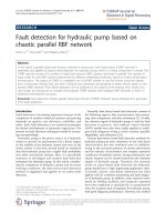
Let us consider parallel manipulators corresponding to
three-member and four-member screw groups. We use
the notification (Figure 1.): (a) actuated prismatic pair
(linear actuator), (b) actuated rotation pair (rotating
actuator), (c) twist of zero pitch, (d) twist of infinite
pitch, (e) wrench of zero pitch, (f) wrench of infinite
pitch.
a) b) c) d) e) f)
Figure. 1 Twists and wrenches
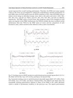
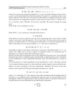
Firstly, let us consider a spherical parallel mechanism
(Figure 2a). Each kinematic chain consists of one
actuated rotation pair (rotating actuator) situated on the
base and two passive rotation kinematic pairs. The unit
screws of the axes of these kinematic pairs have
coordinates (note that the origin of the coordinate
system is the point O in which the axes of all the pairs
intersect): E
11
(1, 0, 0, 0, 0, 0), E
12
(e
12x
, e
12y
, e
12z
, 0, 0,
0), E
13
(e
13x
, e
13y
, e
13z
, 0, 0, 0), E
21
(0, 1, 0, 0, 0, 0),
E
22
(e
22x
, e
22y
, e
22z
, 0, 0, 0), E
23
(e
23x
, e
23y
, e
23z
, 0, 0, 0),
E
31
(0, 0, 1, 0, 0, 0), E
32
(e
32x
, e
32y
, e
32z
, 0, 0, 0), E
33
(e
33x
,
e
33y
, e
33z
, 0, 0, 0).
All the screws are of zero pitch. All three kinematic
chains impose the same constraints, so that one can
insert other similar chains between the base and
moving platform and the degree of freedom will remain
equal to three. The wrenches of the constraints imposed
by kinematic chains have coordinates (Figure 2, b): R
1
(1, 0, 0, 0, 0, 0), R
2
(0, 1, 0, 0, 0, 0), R
3
(0, 0, 1, 0, 0, 0),
these wrenches are of zero pitch. All the twists of
motions of the platform can be represented by the
twists reciprocal to the wrenches of the imposed
constraints (Figure 2b):
1
(1, 0, 0, 0, 0, 0),
2
(0, 1, 0,
0, 0, 0),
3
(0, 0, 1, 0, 0, 0). All three twists are of zero
pitch.
In this mechanism singularities expressed by loss of
one degree of freedom exist if any three screws E
i1
, E
i2
, E
i3
(i = 1, 2, 3) are linearly dependent which is
possible if they are coplanar (they are situated in the
same plane). In particular if the unit screws E
11
(1, 0, 0,
0, 0, 0), E
12
(e
12x
, e
12y
, e
12z
, 0, 0, 0), E
13
(e
13x
, e
13y
, e
13z
,
0, 0, 0) are coplanar (Figure 2, c) then there exist four
wrenches of constraints imposed by kinematic chains:
Hội nghị toàn quốc về Điều khiển và Tự động hoá - VCCA-2011
VCCA-2011 I-5
R
1
(1, 0, 0, 0, 0, 0), R
2
(0, 1, 0, 0, 0, 0), R
3
(0, 0, 1, 0, 0,
0) and R
4
(0, 0, 0, 0, r
4y
, r
4z
) and only two twists of
motion of the platform reciprocal to these wrenches
1
(1, 0, 0, 0, 0, 0) and
2
(
2x
,
2y
,
2z
, 0, 0, 0), these
twists are of zero pitch. The wrench R
4
is of infinite
pitch, it is perpendicular to the axes E
11
, E
12
, E
13
.
If the actuators are fixed then there exist six wrenches
imposed by kinematic chains: R
1
(1, 0, 0, 0, 0, 0), R
2
(0,
1, 0, 0, 0, 0), R
3
(0, 0, 1, 0, 0, 0), R
4
(0, 0, 0, r
4x
, r
4y
,
r
4z
), R
5
(0, 0, 0, r
5x
, r
5y
, r
5z
) and R
6
(0, 0, 0, r
6x
, r
6y
, r
6z
).
The wrenches R
4
, R
5
, R
6
are of infinite pitch.
Singularities corresponding to non-controlled
infinitesimal motion of the moving platform (end -
effector) exist if the wrenches R
1
, R
2
, R
3
, R
4
, R
5
, R
6
are linearly dependent which is possible if the wrenches
R
4
, R
5
, R
6
are coplanar. In this case the twist of zero
pitch
(
x
,
y
,
z
, 0, 0, 0) exists which is
perpendicular to the axes of the wrenches R
4
, R
5
, R
6
and therefore reciprocal to all the wrenches R
1
, R
2
, R
3
,
R
4
, R
5
, R
6
.
Figure. 2 Spherical parallel mechanism
Moreover singularities exist corresponding both to loss
of one degree of freedom and to non-controlled motion
of the moving platform. By this any three screws E
i1
,
E
i2
, E
i3
(i = 1, 2, 3) and the wrenches R
1
, R
2
, R
3
, R
4
,
R
5
, R
6
are linearly dependent.
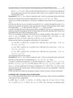
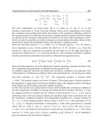
Now let us consider a planar parallel mechanism
(Figure 3a). Each kinematic chain can consist of one
rotation kinematic pair and two prismatic kinematic
pairs (the axis of the rotation pair is perpendicular to
the axes of the prismatic pairs), or of two rotation
kinematic pair and one prismatic kinematic pair (the
axes of the rotation pairs are parallel to each other and
are perpendicular to the axis of the prismatic pair), or of
three rotation kinematic pairs with parallel axes. In our
mechanism two kinematic chains consist of three
rotation kinematic pairs (one of them is actuated and
situated on the base) and one kinematic chains consists
of one actuated rotation kinematic pair situated on the
base (rotating actuator) and two prismatic kinematic
pairs represented as four-bar parallelograms. The unit
screws of the axes of these kinematic pairs have
coordinates: E
11
(0, 0, 1, 0, 0, 0), E
12
(0, 0, 1, e
12x
, e
12y
,
0), E
13
(0, 0, 1, e
13x
, e
13y
, 0), E
21
(0, 0, 1, 0, 0, 0), E
22
(0,
0, 1, e
22x
, e
22y
, 0), E
23
(0, 0, 1, e
23x
, e
23y
, 0), E
31
(0, 0, 1,
0, 0, 0), E
32
(0, 0, 0, e
32x
, e
32y
, 0), E
33
(0, 0, 0, e
33x
, e
33y
,
0).
The screws E
32
and E
33
are of infinite pitch. All other
screws are of zero pitch. All three kinematic chains
impose the same constraints, so that one can insert
other similar chains between the base and moving
platform and the degree of freedom will remain equal
to three. The wrenches of the constraints imposed by
kinematic chains have coordinates (Figure 3b): R
1
(0, 0,
0, 1, 0, 0), R
2
(0, 0, 0, 0, 1, 0), R
3
(0, 0, 1, 0, 0, 0). All
the twists of motions of the platform can be represented
by the twists reciprocal to the wrenches of the imposed
constraints (Figure 3b):
1
(0, 0, 0, 1, 0, 0),
2
(0, 0, 0,
O
O
2
3
1
R
1
R
3
R
2
z
y
x
E
13
E
12
E
11
E
33
E
32
E
31
E
23
E
22
E
21
O
R
4
R
3
1
R
1
R
2
2
z
y
x
a)
b)
c)
Hội nghị toàn quốc về Điều khiển và Tự động hoá - VCCA-2011
VCCA-2011 I-6
0, 1, 0),
3
(0, 0, 1, 0, 0, 0). The twists
1
and
2
are of
infinite pitch, the twist
3
is of zero pitch.
In this mechanism singularities corresponding to loss of
one degree of freedom exist if three screws E
i1
, E
i2
and
E
i3
(i = 1, 2, 3) are linearly dependent which is possible
if three screws E
i1
, E
i2
and E
i3
(i = 1, 2) are situated in
the same plane or if two screws E
32
, E
33
are parallel. In
particular if E
32
= E
33
(Figure 3, c) then there exist four
wrenches of constraints imposed by the kinematic
chains: R
1
(0, 0, 0, 1, 0, 0), R
2
(0, 0, 0, 0, 1, 0), R
3
(0, 0,
1, 0, 0, 0), R
4
(r
4x
, r
4y
,, 0, 0, 0, 0) and only two twists of
motion of the platform reciprocal to these wrenches
1
(0, 0, 0, v
1x
, v
1y
,, 0) and
2
(0, 0, 1, 0, 0, 0). Note that R
4
is perpendicular to E
32
and E
33
, and
1
is parallel to
them.
If the actuators are fixed then there exist six wrenches
imposed by the kinematic chains: R
1
(0, 0, 0, 1, 0, 0),
R
2
(0, 0, 0, 0, 1, 0), R
3
(0, 0, 1, 0, 0, 0), R
4
(r
4x
, r
4y
, 0, 0,
0, 1), R
5
(r
5x
, r
5y
, 0, 0, 0, 1) and R
6
(0, 0, 0, 0, 0
, 1). The
wrenches R
4
and R
5
, are of zero pitch, they are situated
along the axes of the links connecting passive rotation
pairs of the first and the second kinematic chains. R
6
is
of infinite pitch. Singularities corresponding to non-
controlled infinitesimal motions of the moving
platform exist if the wrenches R
1
, R
2
, R
3
, R
4
, R
5
, R
6
are linearly dependent which is possible if the wrenches
R
4
, and R
5
coincide. In this case the twist of infinite
pitch
(0, 0, 0, v
x
, v
y
, 0) exists which is perpendicular
to the axes of the wrenches R
4
and R
5
and therefore
reciprocal to all the wrenches R
1
, R
2
, R
3
, R
4
, R
5
, R
6
.
Note that singularities exist corresponding both to loss
of one degree of freedom and to non-controlled
infinitesimal motion of the moving platform. By this
any three screws E
i1
, E
i2
, E
i3
(i = 1, 2, 3) and the
wrenches R
1
, R
2
, R
3
, R
4
, R
5
, R
6
are linearly dependent.
Figure. 3 Planar parallel mechanism
This mechanism is particularly decoupled. The matter
is that in the third kinematc chain the input link of the
first parallelogram and the output link of the second
parallelogram are connected correspondingly to the
rotating actuator ant to the end-effector in the middles
of these links, and the output link of the first
parallelogram and the input link of the second
parallelogram coincide. It causes that the first and the
second actuators drive the position of the end-effector.
R
4
E
21
E
32
O
2
3
1
R
1
R
3
R
2
z
y
x
O
R
3
R
1
R
2
1
z
y
x
E
22
E
12
E
11
E
33
E
31
E
13
E
23
2
E
13
E
23
a)
b)
c)
Hội nghị toàn quốc về Điều khiển và Tự động hoá - VCCA-2011
VCCA-2011 I-7
The third actuator drives the orientation of the end-
effector.
Now let us consider a parallel mechanism of
Schoenflies motions (Figure 4a). The first and the
second kinematic chains consist of one actuated
prismatic pair (linear actuator) situated on the base, two
prismatic kinematic pairs represented as four-bar
parallelograms and one rotation kinematic pair (the
axes of rotation pairs of these two chains coincide). The
third kinematic chain consists of one actuated rotation
pair (rotating actuator) situated on the base, one
actuated prismatic pair (linear actuator) (the axes of
rotating and linear actuators coincide) and two
prismatic kinematic pairs represented as four-bar
parallelograms. The unit screws of the axes of these
kinematic pairs have coordinates: E
11
(0, 0, 0, 1, 0, 0),
E
12
(0, 0, 0, 0, e
12y
, e
12z
), E
13
(0, 0, 0, 0, e
13y
, e
13z
), E
14
(0, 0, 1, 0, 0, 0), E
21
(0, 0, 0, 0, 1, 0), E
22
(0, 0, 0, e
22x
, 0,
e
22z
), E
23
(0, 0, 0, e
23x
, 0, e
23z
), E
24
(0, 0, 1, 0, 0, 0), E
31
(0, 0, 1, 0, 0, 0), E
32
(0, 0, 0, 0, 0, 1), E
33
(0, 0, 0, e
33x
,
e
33y
, 0), E
34
(0, 0, 0, e
34x
, e
34y
, 0).
The screws E
11
, E
12
, E
13
, E
21
, E
22
, E
23
, E
32
, E
33
and E
34
are of infinite pitch. All other screws are of zero pitch.
All three kinematic chains impose the same constraints,
so that one can insert other similar chains between the
base and moving platform and the degree of freedom
will remain equal to four. The wrenches of the
constraints imposed by kinematic chains have
coordinates (Figure 4, b): R
1
(0, 0, 0, 1, 0, 0), R
2
(0, 0,
0, 0, 1, 0). All the twists of motions of the platform can
be represented by the twists reciprocal to the wrenches
of the imposed constraints (Figure 4b):
1
(0, 0, 0, 1, 0,
0),
2
(0, 0, 0, 0, 1, 0),
3
(0, 0, 0, 0, 0, 1),
4
(0, 0, 1,
0, 0, 0). The twists
1
,
2
and
3
are of infinite pitch,
the twist
4
is of zero pitch.
Figure. 4 Schoenflies motion parallel mechanism
R
3
3
z
4
z
O
O
1
R
1
R
2
2
E
21
E
23
2
3
1
R
1
E
34
E
33
E
32
E
13
E
12
E
11
R
2
y
x
y
x
E
22
E
14
E
24
E
31
a)
b)
c)
Hội nghị toàn quốc về Điều khiển và Tự động hoá - VCCA-2011
VCCA-2011 I-8
In this mechanism singularities corresponding to loss of
one degree of freedom exist if four screws E
i1
, E
i2
, E
i3
and E
i4
(i = 1, 2, 3) are linearly dependent which is
possible if any two screws E
12
and E
13
, or E
22
and E
23
,
or E
33
and E
34
are parallel. In particular if E
22
(0, 0, 0,
1, 0, 0) = E
23
(0, 0, 0 , 1, 0, 0) (Figure 4, c) then there
exist three wrenches of constraints imposed by the
kinematic chains: R
1
(0, 0, 0, 1, 0, 0), R
2
(0, 0, 0, 0, 1, 0)
and R
3
(0, 0, 1, 0, 0, 0) and only three twists of motion
of the platform reciprocal to these wrenches
1
(0, 0, 0,
1, 0, 0),
1
(0, 0, 0, 0, 1, 0) and
3
(0, 0, 1, 0, 0, 0).
Note that R
3
is perpendicular to E
22
and E
23
, and
1
is
parallel to them.
If the actuators are fixed then there exist six wrenches
imposed by the kinematic chains: R
1
(0, 0, 0, 1, 0, 0),
R
2
(0, 0, 0, 0, 1, 0), R
3
(1, 0, 0, 0, 0, 0), R
4
(0, 1, 0, 0, 0,
0), R
5
(0, 0, 0, 0, 0, 1) and R
6
(0, 0, 1, 0, 0, 0). The
wrenches R
3
, R
4
, R
6
are of zero pitch, the wrench R
5
is of infinite pitch.
This mechanism is particularly decoupled and
isotropic. Each linear actuator controls the motion of
the platform along one Cartesian coordinate. In the
third kinematc chain the input link of the first
parallelogram and the output link of the second
parallelogram are connected correspondingly to the
rotating actuator ant to the end-effector in the middles
of these links, and the output link of the first
parallelogram and the input link of the second
parallelogram coincide. It causes that the rotating
actuator drives the orientation of the end-effector. The
linear actuators drive the position of the end-effector.
These mechanisms will be used for synthesis of 6-DOF
parallel decupled manipulators.
4. Structural synthesis of 6-DOF decoupled
parallel mechanisms
Let us consider 6-DOF parallel decoupled manipulators
synthesized by using of the mechanisms represented
above. The condition of decoupling is that the linear
actuators control only translation motions and rotating
actuators control only orientation motions. If linear
actuators are fixed then the position of the moving
platform is fixed. If rotating actuators are fixed then the
orientation of the moving platform is fixed. The
approach which we use is combining of 3-DOF parallel
translation and orientation mechanisms.
Firstly we consider 6-DOF parallel mechanism (Figure
5a) 3 P-P-P-R-R-R. Each kinematic chain consists of
one actuated prismatic pair (linear actuator) situated on
the base, two prismatic kinematic pairs represented as
four-bar parallelograms, one actuated rotation pair
(rotating actuator) and two passive rotation pairs. The
axes of all the rotation pairs intersect in the same point
O which is the origin of the coordinate system. This
point O is movable but the directions of the coordinate
axes are constant.
The unit screws of the axes of these kinematic pairs
have coordinates: E
11
(0, 0, 0, 1, 0, 0), E
12
(0, 0, 0, 0,
e
12y
, e
12z
), E
13
(0, 0, 0, 0, e
13y
, e
13z
), E
14
(1, 0, 0, 0, 0, 0),
E
15
(e
12x
, e
12y
, e
12z
, 0, 0, 0), E
16
(e
16x
, e
16y
, e
16z
, 0, 0, 0),
E
21
(0, 0, 0, 0, 1, 0), E
22
(0, 0, 0, e
22x
, 0, e
22z
), E
23
(0, 0,
0, e
23x
, 0, e
23z
), E
24
(0, 1, 0, 0, 0, 0), E
25
(e
25x
, e
25y
, e
25z
,
0, 0, 0), E
26
(e
26x
, e
26y
, e
26z
, 0, 0, 0), E
31
(0, 0, 0, 0, 0, 1),
E
32
(0, 0, 0, e
32x
, e
32y
, 0), E
33
(0, 0, 0, e
33x
, e
33y
, 0). E
34
(0,
0, 1, 0, 0, 0), E
35
(e
35x
, e
35y
, e
35z
, 0, 0, 0), E
36
(e
36x
, e
36y
,
e
36z
, 0, 0, 0). The screws E
i1
, E
i2
, E
i3
are of infinite
pitch, the screws E
i4
, E
i5
, E
i6
are of zero pitch (i = 1, 2,
3). This mechanism is particularly isotropic so that
each linear actuator corresponds to one Cartesian
coordinate x, y or z.
All six twists of motions of the platform can be
represented as:
1
(1, 0, 0, 0, 0, 0),
2
(0, 1, 0, 0, 0, 0),
3
(0, 0, 1, 0, 0, 0),
4
(0, 0, 0, 1, 0, 0),
5
(0, 0, 0, 0, 1,
0),
6
(0, 0, 0, 0, 0, 1).
In this mechanism singularities expressed by loss of
one or more degrees of freedom exist if any six screws
E
i1
, E
i2
, E
i3
, E
i4
, E
i5
, E
i6
(i = 1, 2, 3) are linearly
dependent which is possible if any two screws E
i2
, E
i3
are parallel or if any three screws E
i4
, E
i5
, E
i6
are
coplanar. In particular if E
22
(0, 0, 0, 1, 0, 0) = E
23
(0,
0, 0 , 1, 0, 0) then there exist one wrench of the
constraint imposed by the second kinematic chain: R
(0, 0, 1, 0, 0, 0) and only five twists of motion of the
platform reciprocal to this wrench
1
(1, 0, 0, 0, 0, 0),
2
(0, 1, 0, 0, 0, 0),
3
(0, 0, 1, 0, 0, 0),
4
(0, 0, 0, 1,
0, 0) and
5
(0, 0, 0, 0, 1, 0). If the unit screws E
14
(1,
0, 0, 0, 0, 0), E
15
(e
15x
, e
15y
, e
15z
, 0, 0, 0), E
16
(e
16x
, e
16y
,
e
16z
, 0, 0, 0) are coplanar then there exist one wrench of
constraint imposed by the first kinematic chain: R (0, 0,
0, 0, r
y
, r
z
) and only five twists of motion of the
platform reciprocal to this wrench
1
(1, 0, 0, 0, 0, 0),
2
(
2x
,
2y
,
2z
, 0, 0, 0),
3
(0, 0, 0, 1, 0, 0),
4
(0,
0, 0, 0, 1, 0),
5
(0, 0, 0, 0, 0, 1). The wrench R is of
infinite pitch, it is perpendicular to the axes E
14
, E
15
,
E
16
.
If the actuators are fixed then the wrenches of the
constraints imposed by the kinematic chains have
coordinates (Figure 5b): R
11
(1, 0, 0, 0, 0, 0), R
12
(0, 0,
0, r
12x
, r
12y
, r
12z
), R
21
(0, 1, 0, 0, 0, 0), R
22
(0, 0, 0, r
22x
,
r
22y
, r
22z
), R
31
(0, 0, 1, 0, 0, 0), R
32
(0, 0, 0, r
32x
, r
32y
,
r
32z
). The wrenches R
i1
and R
i2
are imposed by the i-th
kinematic chain. The wrenches R
i1
are of zero pitch, the
wrenches R
i2
are of infinite pitch (i = 1, 2, 3).
Singularities corresponding to non-controlled
infinitesimal motion of the moving platform exist if the
wrenches R
11
, R
12
, R
21
, R
22
, R
31
, R
32
are linearly
dependent. It is possible if the wrenches R
12
, R
22
, R
32
are coplanar (Figure 5c). In this case the twist of zero
pitch
(
x
,
y
,
z
, 0, 0, 0) exists which is
perpendicular to the axes of the wrenches R
12
, R
22
, R
32
and therefore reciprocal to all the wrenches R
11
, R
12
,
R
21
, R
22
, R
31
, R
32
.
In this mechanism singularities exist corresponding
both to loss of one degree of freedom and to non-
Hội nghị toàn quốc về Điều khiển và Tự động hoá - VCCA-2011
VCCA-2011 I-9
controlled infinitesimal motion of the moving platform.
By this any six screws E
i1
, E
i2
, E
i3
, E
i4
, E
i5
, E
i6
(i = 1,
2, 3) and the wrenches R
1
, R
2
, R
3
, R
4
, R
5
, R
6
are
linearly dependent. The corresponding conditions are
represented above.
Figure. 5 6-DOF parallel mechanism 3 P-P-P-R-R-R
Now let us consider 6-DOF mechanism 3 R-R-R-P-P-P
in which the rotating actuators are situated on the base
and the linear actuators are situated in moving
kinematic pairs (Figure 6a). Each kinematic chain
consists of one actuated rotation pair (rotating
actuator), two passive rotation pairs, one actuated
prismatic pair (linear actuator) and two prismatic
kinematic pairs represented as four-bar parallelograms.
The axes of all the rotation pairs intersect in the same
point O which is the origin of the coordinate system.
The position of this point O is constant but the
directions of the coordinate axes rotate corresponding
to the rotations of the axes of the linear actuators. The
unit screws of the axes of these kinematic pairs have
coordinates: E
11
(1, 0, 0, 0, 0, 0), E
12
(e
12x
, e
12y
, e
12z
, 0,
0, 0), E
13
(e
13x
, e
13y
, e
13z
, 0, 0, 0), E
14
(0, 0, 0, 1, 0, 0),
E
15
(0, 0, 0, 0, e
15y
, e
15z
), E
16
(0, 0, 0, 0, e
16y
, e
16z
), E
21
(0,
1, 0, 0, 0, 0), E
22
(e
22x
, e
22y
, e
22z
, 0, 0, 0), E
23
(e
23x
, e
23y
,
e
23z
, 0, 0, 0), E
24
(0, 0, 0, 0, 1, 0), E
25
(0, 0, 0, e
25x
, 0,
e
25z
), E
26
(0, 0, 0, e
26x
, 0, e
26z
), E
31
(0, 0, 1, 0, 0, 0), E
32
(e
32x
, e
32y
, e
32z
, 0, 0, 0), E
33
(e
33x
, e
33y
, e
33z
, 0, 0, 0), E
34
(0, 0, 0, 0, 0, 1), E
35
(0, 0, 0, e
35x
, e
35y
, 0), E
36
(0, 0, 0,
e
36x
, e
36y
, 0). The screws E
i1
, E
i2
, E
i3
are of zero pitch,
the screws E
i4
, E
i5
, E
i6
are of infinite pitch (i = 1, 2, 3).
This mechanism is particularly decoupled as the
O
1
O
E
22
E
11
E
34
E
24
E
25
E
14
E
16
E
15
E
26
E
36
E
35
E
13
E
12
E
33
E
32
E
31
E
21
E
23
O
R
22
R
32
R
12
R
11
R
31
R
21
z
y
x
R
22
R
12
R
11
R
31
R
21
z
y
x
a)
b)
c)
Hội nghị toàn quốc về Điều khiển và Tự động hoá - VCCA-2011
VCCA-2011 I-10
position of the point O is constant by any motions in
linear actuators.
All six twists of motions of the platform can be
represented as:
1
(1, 0, 0, 0, 0, 0),
2
(0, 1, 0, 0, 0, 0),
3
(0, 0, 1, 0, 0, 0),
4
(0, 0, 0, 1, 0, 0),
5
(0, 0, 0, 0, 1,
0),
6
(0, 0, 0, 0, 0, 1).
In this mechanism singularities expressed by loss of
one or more degrees of freedom exist if any six screws
E
i1
, E
i2
, E
i3
, E
i4
, E
i5
, E
i6
(i = 1, 2, 3) are linearly
dependent which is possible if any two screws E
i5
, E
i6
are parallel or if any three screws E
i1
, E
i2
, E
i3
are
coplanar. In particular if E
25
(0, 0, 0, 1, 0, 0) = E
26
(0,
0, 0, 1, 0, 0) then there exist one wrench of the
constraint imposed by the second kinematic chain: R
(0, 0, 1, 0, 0, 0) and only five twists of motion of the
platform reciprocal to this wrench
1
(1, 0, 0, 0, 0, 0),
2
(0, 1, 0, 0, 0, 0),
3
(0, 0, 1, 0, 0, 0),
4
(0, 0, 0, 1, 0,
0) and
5
(0, 0, 0, 0, 1, 0). If the unit screws E
11
(1, 0,
0, 0, 0, 0), E
12
(e
12x
, e
12y
, e
12z
, 0, 0, 0), E
13
(e
13x
, e
13y
, e
13z
, 0, 0, 0) are coplanar then there exist one wrench of the
constraint imposed by the first kinematic chain: R (0, 0,
0, 0, r
y
, r
z
) and only five twists of motion of the
platform reciprocal to this wrench
1
(1, 0, 0, 0, 0, 0),
2
(
2x
,
2y
,
2z
, 0, 0, 0),
3
(0, 0, 0, 1, 0, 0),
4
(0, 0,
0, 0, 1, 0),
5
(0, 0, 0, 0, 0, 1). The wrench R is of
infinite pitch, it is perpendicular to the axes E
11
, E
12
,
E
13
.
Figure. 6 6-DOF parallel mechanism 3 R-R-R-P-P-P
O
O
E
25
E
23
E
11
E
13
E
14
E
16
E
15
E
12
E
33
E
32
E
31
E
22
E
21
E
36
E
35
E
34
E
24
E
26
1
O
R
21
R
31
R
11
R
12
R
32
R
22
z
y
x
R
21
R
11
R
12
R
31
R
22
z
y
x
a)
b)
c)
Hội nghị toàn quốc về Điều khiển và Tự động hoá - VCCA-2011
VCCA-2011 I-11
Singularities corresponding to non-controlled
infinitesimal motion of the moving platform exist if the
wrenches R
11
, R
12
, R
21
, R
22
, R
31
, R
32
are linearly
dependent. It is possible if the wrenches R
11
, R
21
, R
31
are coplanar (Figure 6c). In this case the twist of zero
pitch
(
x
,
y
,
z
, 0, 0, 0) exists which is
perpendicular to the axes of the wrenches R
11
, R
21
, R
31
and therefore reciprocal to all the wrenches R
11
, R
12
,
R
21
, R
22
, R
31
, R
32
.
Note that in this mechanism also singularities exist
corresponding both to loss of one degree of freedom
and to non-controlled infinitesimal motion of the
moving platform. By this any six screws E
i1
, E
i2
, E
i3
,
E
i4
, E
i5
, E
i6
(i = 1, 2, 3) and the wrenches R
1
, R
2
, R
3
,
R
4
, R
5
, R
6
are linearly dependent. The corresponding
conditions are represented above.
Obviously it is more preferable to situate the actuators
as close to the base as possible. One can direct the axes
of the linear actuator and of the rotating actuator along
the same line. Let us consider 6-DOF mechanism 3 R-
P-P-P-R-R in which the rotating actuators are situated
on the base and the axes of linear actuators coincide
with the axes of rotating actuators. (Figure 7a). Each
kinematic chain consists of one actuated rotation pair
(rotating actuator) situated on the base, one actuated
prismatic pair (linear actuator), two prismatic kinematic
pairs represented as four-bar parallelograms and two
passive rotation pairs.
The axes of all the passive rotation pairs intersect in the
same point O which is the origin of the coordinate
system. This point O is movable but the directions of
the coordinate axes are constant. The unit screws of the
axes of these kinematic pairs have coordinates: E
11
(1,
0, 0, 0, 0, 0), E
12
(0, 0, 0, 1, 0, 0), E
13
(0, 0, 0, 0, e
13y
,
e
13z
), E
14
(0, 0, 0, 0, e
14y
, e
14z
), E
15
(e
15x
, e
15y
, e
15z
, 0, 0,
0), E
16
(e
16x
, e
16y
, e
16z
, 0, 0, 0), E
21
(0, 1, 0, 0, 0, 0), E
22
(0, 0, 0, 0, 1, 0), E
23
(0, 0, 0, e
23x
, 0, e
23z
), E
24
(0, 0, 0,
e
24x
, 0, e
24z
), E
25
(e
25x
, e
25y
, e
25z
, 0, 0, 0), E
26
(e
26x
, e
26y
,
e
26z
, 0, 0, 0), E
31
(0, 0, 1, 0, 0, 0), E
32
(0, 0, 0, 0, 0, 1),
E
33
(0, 0, 0, e
33x
, e
33y
, 0), E
34
(0, 0, 0, e
34x
, e
34y
, 0), E
35
(e
35x
, e
35y
, e
35z
, 0, 0, 0), E
36
(e
36x
, e
36y
, e
36z
, 0, 0, 0). The
screws E
i1
, E
i5
, E
i6
are of zero pitch, the screws E
i2
, E
i3
,
E
i4
are of infinite pitch (i = 1, 2, 3).
All six twists of motions of the platform can be
represented as:
1
(1, 0, 0, 0, 0, 0),
2
(0, 1, 0, 0, 0, 0),
3
(0, 0, 1, 0, 0, 0),
4
(0, 0, 0, 1, 0, 0),
5
(0, 0, 0, 0, 1,
0),
6
(0, 0, 0, 0, 0, 1). If rotating actuators are fixed
then the linear actuators drive translation motions of the
end-effector analogously to the mechanism drown in
the Figure 2. By this the kinematic pairs corresponding
to the screws E
i2
, E
i3
, E
i4
are used. If linear actuators
are fixed then the rotating actuators drive orientation
motions of the end-effector analogously to the
mechanism drown in the Figure 2. By this the
kinematic pairs corresponding to the screws E
i1
, E
i5
, E
i6
are used but the rotations are transferred by the
parallelogram analogously to the thirds kinematic
chains of the mechanisms drown in the Figures 4, 5.
In considered mechanism (Figure 7a) singularities
expressed by loss of one or more degrees of freedom
exist if any six screws E
i1
, E
i2
, E
i3
, E
i4
, E
i5
, E
i6
(i = 1,
2, 3) are linearly dependent. Analogously to previous
cases it is possible if any two screws E
i3
, E
i4
are
parallel or if any three screws E
i1
, E
i2
, E
i3
are coplanar.
In particular if E
23
(0, 0, 0, 1, 0, 0) = E
24
(0, 0, 0, 1, 0,
0) then there exists one wrench of the constraint
imposed by the second kinematic chain: R (0, 0, 1, 0, 0,
0) and only five twists of motion of the platform
reciprocal to this wrench
1
(1, 0, 0, 0, 0, 0),
2
(0, 1,
0, 0, 0, 0),
3
(0, 0, 1, 0, 0, 0),
4
(0, 0, 0, 1, 0, 0) and
5
(0, 0, 0, 0, 1, 0). If the unit screws E
11
(1, 0, 0, 0, 0,
0), E
15
(e
15x
, e
15y
, e
15z
, 0, 0, 0), E
16
(e
16x
, e
16y
, e
16z
, 0, 0,
0) are coplanar then there exists one wrench of the
constraint imposed by the first kinematic chain: R (0, 0,
0, 0, r
y
, r
z
) and only five twists of motion of the
platform reciprocal to this wrench
1
(1, 0, 0, 0, 0, 0),
2
(
2x
,
2y
,
2z
, 0, 0, 0),
3
(0, 0, 0, 1, 0, 0),
4
(0, 0,
0, 0, 1, 0),
5
(0, 0, 0, 0, 0, 1). The wrench R is of
infinite pitch, it is perpendicular to the axes E
11
, E
15
,
E
16
.
If the actuators are fixed then the wrenches of the
constraints imposed by the kinematic chains have
coordinates (Figure 7b): R
11
(0, 0, 0, r
11x
, r
11y
, r
11z
), R
12
(1, 0, 0, 0, 0, 0), R
21
(0, 0, 0, r
21x
, r
21y
, r
21z
), R
22
(0, 1, 0,
0, 0, 0), R
31
(0, 0, 0, r
31x
, r
31y
, r
31z
), R
32
(0, 0, 1, 0, 0, 0).
The wrenches R
i1
and R
i2
are imposed by the i-th
kinematic chain. The wrenches R
i1
are of infinite pitch,
the wrenches R
i2
are of zero pitch (i = 1, 2, 3). The
wrenches R
i1
are perpendicular to the screws E
i5
and
E
i6
.
Singularities corresponding to non-controlled
infinitesimal motion of the moving platform exist if the
wrenches R
11
, R
12
, R
21
, R
22
, R
31
, R
32
are linearly
dependent. It is possible if the wrenches R
11
, R
21
, R
31
are coplanar (Figure 7c). In this case the twist of zero
pitch
(
x
,
y
,
z
, 0, 0, 0) exists which is
perpendicular to the axes of the wrenches R
11
, R
21
, R
31
and therefore reciprocal to all the wrenches R
11
, R
12
,
R
21
, R
22
, R
31
, R
32
.
Note that in this mechanism also singularities exist
corresponding both to loss of one degree of freedom
and to non-controlled infinitesimal motion of the
moving platform. By this any six screws E
i1
, E
i2
, E
i3
,
E
i4
, E
i5
, E
i6
(i = 1, 2, 3) and the wrenches R
1
, R
2
, R
3
,
R
4
, R
5
, R
6
are linearly dependent. The corresponding
conditions are represented above.
Hội nghị toàn quốc về Điều khiển và Tự động hoá - VCCA-2011
VCCA-2011 I-12
Figure. 7 6-DOF parallel mechanism 3 R-P-P-P-R-R
This mechanism is decoupled and particularly
isotropic. Each linear actuator controls the motion of
the platform along one Cartesian coordinate. In each
kinematc chain the input link of the first parallelogram
and the output link of the second parallelogram are
connected correspondingly to the linear actuator ant to
the passive rotation kinematic pair in the middles of
these links, and the output link of the first
parallelogram and the input link of the second
parallelogram coincide. It causes that only the rotating
actuators drive the orientation of the end-effector. The
linear actuators drive the position of the end-effector.
Note that the axes of the screws E
i1
and E
i2
can be not
coinciding but the axes of the screws E
i3
and E
i4
must
be perpendicular to the axis of the screw E
i1
.
This mechanism is similar to the mechanisms
considered in [18 - 20] but here the prismatic kinematic
pairs are represented as four-bar planar parallelograms
as in [11 – 13]. It causes an advantage that the rotation
motions are translated without the sliding motions in
prismatic kinematic pairs. Therefore the mechanism in
Figure 7 is more practically applicable than the
mechanisms represented in [18 – 20].
5. 6 DOF decoupled parallel mechanisms
with U-joints and additional constraints
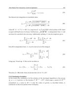
Now let us consider a 6-DOF decoupled parallel
mechanism (Figure 8a). Each kinematic chain consists
of one rotating actuator situated on the base, one
linear actuator, two prismatic kinematic pairs
represented as two U-joints with additional
constraints and two passive rotation pairs.
The axes of all the passive rotation pairs intersect in
the same point O which is the origin of the coordinate
system. This point O is movable but the directions of
the coordinate axes are constant. The unit screws of
the axes of kinematic pairs have coordinates: E
11
(1,
0, 0, 0, 0, 0), E
12
(0, 0, 0, 1, 0, 0), E
13
(0, 0, 0, e
o
13x
,
e
o
13 y
, e
o
13z
), E
14
(0, 0, 0, e
o
14x
, e
o
14 y
, e
o
14z
), E
15
(e
15x
,
e
15y
, e
15z
, 0, 0, 0), E
16
(e
16x
, e
16y
, e
16z
, 0, 0, 0), E
21
(0,
O
E
36
E
35
E
14
E
13
E
12
E
11
E
16
E
15
E
31
E
34
E
33
E
32
E
23
E
22
E
24
E
26
E
25
E
21
O
1
O
R
22
R
32
R
12
R
11
R
31
R
21
z
y
x
R
22
R
12
R
11
R
31
R
21
z
y
x
a)
b)
c)
Hội nghị toàn quốc về Điều khiển và Tự động hoá - VCCA-2011
VCCA-2011 I-13
1, 0, 0, 0, 0), E
22
(0, 0, 0, 0, 1, 0), E
23
(0, 0, 0, e
o
23x
,
e
o
23 y
, e
o
23z
), E
24
(0, 0, 0, e
o
24x
, e
o
24 y
, e
o
24z
), E
25
(e
25x
,
e
25y
, e
25z
, 0, 0, 0), E
26
(e
26x
, e
26y
, e
26z
, 0, 0, 0), E
31
(0,
0, 1, 0, 0, 0), E
32
(0, 0, 0, 0, 0, 1), E
33
(0, 0, 0, e
o
33x
,
e
o
33 y
, e
o
33z
), E
34
(0, 0, 0, e
o
34x
, e
o
34 y
, e
o
34z
), E
35
(e
35x
,
e
35y
, e
35z
, 0, 0, 0), E
36
(e
36x
, e
36y
, e
36z
, 0, 0, 0). The
screws E
i1
, E
i5
, E
i6
are of zero pitch, the screws E
i2
,
E
i3
, E
i4
are of infinite pitch (i = 1, 2, 3).
Figure. 8 6 DOF decoupled parallel mechanism with U-joints and additional constraint
All six twists of motions of the platform can be
represented as:
1
(1, 0, 0, 0, 0, 0),
2
(0, 1, 0, 0, 0,
0),
3
(0, 0, 1, 0, 0, 0),
4
(0, 0, 0, 1, 0, 0),
5
(0, 0, 0,
0, 1, 0),
6
(0, 0, 0, 0, 0, 1). If rotating actuators are
fixed then the linear actuators drive translational
motions of the end-effector. By this the kinematic
pairs corresponding to the screws E
i2
, E
i3
, E
i4
are
used. If linear actuators are fixed then the rotating
actuators drive orientation motions of the end-
effector. By this the kinematic pairs E
i1
, E
i5
, E
i6
are
used and rotations are transferred by the U-joints.
In considered mechanism (Figure 8a) singularities
expressed by loss of one or more degrees of freedom
exist if any six screws E
i1
, E
i2
, E
i3
, E
i4
, E
i5
, E
i6
(i =
1, 2, 3) are linearly dependent. It is possible if at least
one of the axes of the links connecting the U-joints is
perpendicular to the axis E
i2
. In particular if the axis
of the link connecting the U-joints of the third chain is
parallel to the y axis then there exists one wrench of
the constraint imposed by this kinematic chain: R (0,
1, 0, 0, 0, 0) and only five twists of motion of the
platform reciprocal to this wrench
1
(1, 0, 0, 0, 0, 0),
2
(0, 0, 1, 0, 0, 0),
3
(0, 0, 1, 0, 0, 0),
4
(0, 0, 0, 1,
0, 0) and
5
(0, 0, 0, 0, 1, 0). If the unit screws E
11
(1,
0, 0, 0, 0, 0), E
15
(e
15x
, e
15y
, e
15z
, 0, 0, 0), E
16
(e
16x
,
e
16y
, e
16z
, 0, 0, 0) are coplanar then there exists one
wrench of the constraint imposed by the first
kinematic chain: R (0, 0, 0, 0, r
o
y
, r
o
z
) and only five
twists of motion of the platform reciprocal to this
wrench
1
(1, 0, 0, 0, 0, 0),
2
(
2x
,
2y
,
2z
, 0, 0, 0),
3
(0, 0, 0, 1, 0, 0),
4
(0, 0, 0, 0, 1, 0),
5
(0, 0, 0, 0,
0, 1). The wrench R is of infinite pitch, it is
perpendicular to the axes E
11
, E
15
, E
16
.
If the actuators are fixed then the wrenches of the
constraints have coordinates (Figure 8b): R
11
(r
11x
, r
11y
, r
11z
, 0, 0, 0), R
12
(0, 0, 0, r
o
12x
, r
o
12y
, r
o
12z
), R
21
(r
21x
,
r
21y
, r
21z
, 0, 0, 0), R
22
(0, 0, 0, r
o
22x
, r
o
22y
, r
o
22z
), R
31
(r
31x
, r
31y
, r
31z
, 0, 0, 0), R
32
(0, 0, 0, r
o
32x
, r
o
32y
, r
o
32z
).
The wrenches R
i1
and R
i2
are imposed by the i-th
kinematic chain. The wrenches R
i1
are of zero pitch,
the wrenches R
i2
are of infinite pitch (i = 1, 2, 3). The
E
11
x
O
R
22
R
32
R
12
R
11
R
31
R
21
z
y
z
B
4
x
A
1,2,3
A
5,6
v*(0,
0,-1)
y
A
4
z
B
6
B
5
B
1
B
2
B
3
ω*(2,
1,0)
y
A
x
B
4
R
22
O
E
21
1
x
y
R
12
R
11
R
31
R
21
E
21
E
23
O
E
36
E
35
E
14
E
13
E
12
E
16
E
15
E
31
E
34
E
33
E
32
E
22
E
24
E
26
a)
b)
c)
Hội nghị toàn quốc về Điều khiển và Tự động hoá - VCCA-2011
VCCA-2011 I-14
wrenches R
i1
are perpendicular to the links connecting
the U-joints, the wrenches R
i2
are perpendicular to the
screws E
i5
and E
i6
.
Singularities corresponding to non-controlled
infinitesimal motion of the moving platform exist if
the wrenches R
11
, R
12
, R
21
, R
22
, R
31
, R
32
are linearly
dependent. It is possible if the wrenches R
11
, R
21
, R
31
or R
12
, R
22
, R
32
are coplanar. In particular if the
wrenches R
12
, R
22
, R
32
are coplanar (Figure 8c) then
the twist
(
x
,
y
,
z
, 0, 0, 0) exists which is
perpendicular to the axes of the wrenches R
12
, R
22
,
R
32
and reciprocal to R
11
, R
12
, R
21
, R
22
, R
31
, R
32
.
In this mechanism, also singularities exist
corresponding both to loss of one degree of freedom
and to non-controlled infinitesimal motion of the
platform. The corresponding conditions are represented
above. This mechanism is decoupled. The rotating
actuators drive the orientation of the end-effector, the
linear actuators drive the position of the end-effector.
6. Conclusion
In this work, the approach to a synthesis of decoupled
parallel manipulators is considered. The approach is
based on the closed screw groups. Synthesized
manipulators consist of three parallel kinematic chains.
The originality of the paper is determined by using of
screw groups. It allows obtaining all the twists of the
moving platform and all the wrenches of the constraints
imposed by kinematic chains without any equations.
Besides it allows avoiding the complications of
Jacobian analysis by considering of the singularities.
References
[1] Hunt, K., Structural Kinematics of In-Parallel-
Actuated Robot Arms, ASME Journal of
Mechanisms, Transmissions, and Automation in
Design, vol. 105, No 4, 1983, pp. 705-712.
[2] Merlet, J P., Parallel Robots (Second Edition).
Springer, 2006.
[3] Kong, X., Gosselin, C., Type Synthesis of
Parallel Mechanisms. Springer, 2007.
[4] Ceccarelli M., Fundamentals of Mechanics of
Robotic Manipulations. Kluwer Academic
Publishers, 2004.
[5] Tsai, L., Robot Analysis: The Mechanics of Serial
and Parallel Manipulators. John Wiley & Sons,
New York.
[6] Huang, Z., The Kinematics and Type Synthesis of
Lower-Mobility Parallel Robot Manipulators.
Proceedings, XI World Congress in Mechanism
and Machine Science, Tianjin, China, 2004,
pp.65-76.
[7] Glazunov, V. A., Koliskor, A. S., Kraynev, A. F.,
Spatial parallel structure Mechanisms. (in Rus.).
Moscow, Nauka, 1991.
[8] Innocenti, C., Parenti-Castelli, V., Direct
kinematics of the 6-4 fully parallel manipulator
with position and orientation uncoupled,
European Robotics and Intelligent Systems Conf.,
Corfou, 23-28 Juin, 1991.
[9] Koliskor, A. Sh., The l-coordinate approach to
the industrial robot design, V IFAC / IFIP /
IMACS / IFORS Symposium, Suzdal, URSS,
April, 22-25, 1986, pp. 108-115.
[10] Mianovski, K., Singularity analysis of parallel
manipulator POLMAN 3
2 with six degrees of
freedom, 12
th
IFToMM World Congress,
Besançon (France), June18-21, 2007.
[11] Mianowski K., On Some Properties of POLMAN-
3L Parallel Manipulator to the use as a 3-D
Measuring System for Industrial/Educational
Applications, Proc. of the WORKSHOP on
Fundamental Issues and Future Research
Directions for Parallel Mechanisms and
Manipulators, Quebec City, Canada, 2002.
[12] Mianowski K., Dynamically Decoupled Parallel
Manipulator With Six Degrees of Freedom for
Fast Assembly, Proc. Int. Conf. ISOM'2002,
Chemnitz, 2002, pp. 274-280.
[13] Clavel, R., Device for Displacing and Positioning
an Element in Space, Patent WO 87/03528, 1987.
[14] Arakelian, V., Guegan, S., Briot, S., Static and
Dynamic Analysis of the PAMINSA, ASME 2005.
International Design Engineering Technical
Conferences & Computers and Information in
Engineering Conference. Long Beach. California,
USA, 2005, pp. 24-28.
[15] Gogu, G., Structural synthesis of fully-isotropic
translational parallel robots via theory of linear
transformations, European Journal of Mechanics,
A/Solids, vol. 23, 2004, pp. 1021-1039.
[16] Gogu, G., Structural Synthesis of Parallel Robots,
Part 1: Methodology, Springer, Dordrecht, 2008.
[17] Gogu, G., Structural Synthesis of Parallel Robots,
Part 2: Translational Topologies with Two and
Three Degrees of Freedom, Springer, Dordrecht,
2009.
[18] Yan Jin, I-Ming Chen, Guilin Yang, Structure
Synthesis and Singularity Analysis of a Parallel
Manipulator Based on Selective Actuation,
Proceedings of the 2004 IEEE International
Conference on Robotics & Automation, New
Orleans, LA April 2004, pp. 4533-4538.
[19] Yan Jin, I-Ming Chen, Guilin Yang, Mobility and
singularity analysis of a selectively actuated
parallel mechanism, Theory and Practice of
Robots and Manipulators. (ROMANSY),
Proceedings of XV CISM-IFToMM Symposium,
Montreal, 2004.
[20] Yan Jin, I-Ming Chen, Guilin Yang, Structure
Synthesis of 6-DOF 3-3 Decoupled Parallel
Manipulators, 12
th
IFToMM World Congress,
Besançon (France), June18-21, 2007.
[21] Dimentberg, F. M., The Screw Calculus and its
Applications in Mechanics. Moscow, Nauka,
1965. (English translation: AD680993,
Hội nghị toàn quốc về Điều khiển và Tự động hoá - VCCA-2011
VCCA-2011 I-15
Clearinghouse for Federal Technical and
Scientific Information, Virginia).
[22] Dimentberg, F. M., The Theory of Screws and Its
Applications. (in Rus.). Moscow, Nauka, 1978.
[23] Herve, J., The Lie group of rigid body
displacements, a fundamental tool for mechanism
design, Mechanism and Machine theory, Vol. 34,
No 8, 1991, pp. 719-730.
[24] Angeles, J., The Qualitative Synthesis of Parallel
Manipulators, Journal of Mechanical Design,
vol. 126, 2004, pp. 617-624.
[25] Sugimoto, K., Existence Criteria for
Overconstrained Mechanisms: An Extension of
Motor Algebra, Tr. ASME, J. of Mech. Design,
No 3, 1990, pp. 295-298.
[26] Glazunov, V. A., Principles of the construction
and analysis of spatial parallel structure
mechanisms, Journal of Machinery Manufacture
and Reliability, Allerton Press Inc., 1995, No 1,
p. 10-15.
[27] Gosselin, C.M., Angeles, J., Singularity Analysis
of Closed Loop Kinematic Chains, IEEE Trans.
on Robotics and Automation, No 6(3), 1990, pp.
281-290.
[28] Glazunov, V.A., Koliskor, A.Sh., Krainev, A.F.,
and Model, B.I., Classification principles and
analysis methods for parallel-structure spatial
mechanisms, Journal of Machinery Manufacture
and Reliability, Allerton Press Inc., No 1, 1990,
pp. 30-37.
[29] Glazunov V. Design of decoupled parallel
manipulators by means of the theory of screws.
Mechanism and Machine Theory. 2010. N 45. P.
239–250.
[30] Tyves L., Glazunov V., Danilin P., Nguyen Minh
Thanh. Decoupled Parallel Manipulator with
Universal Joints and Additional Constraints.
ROMANSY 18. Robot design, dynamics and
control. Proceedings of the eighteenth CISM-
IFToMM Symposium. SpringerWienNewYork.
2010. P.65-72.
I, Victor A. Glazunov, was
born on May 23, 1958 in
Ivanovo Area of Russia. In
1975, I have finished high
school and have entered
Ivanovo Electrical
Engineering Institute. In
1980, I have finished this
institute as the Engineer –
Electrician. Then, I worked
the assistant on stand of
Theoretical and Applied Mechanics of this Institute.
In 1982, I have entered a postgraduate course in the
Blagonravov Mechanical Engineering Research
Institute of the Academy of Sciences of the USSR. In
1986, I finished a postgraduate course and defended a
Candidate thesis under “The kinematic analysis of
spatial mechanisms based on the theory of screws”. In
1992, I finished a preparation for doctor's degree,
after that I have defended a Doctoral thesis under
“Spatial parallel mechanisms”. Since 1992 until the
present time, I work in the Mechanical Engineering
Research Institute of the Russian Academy of
Sciences in high, leading position, and then main
scientific employee. Now, I am the head of the
laboratory of the Theory of mechanisms and structure
of machines.
Again, in 2000, I defended a Candidate philosophy
thesis under “Methodological problems of the theory
of mechanisms” at the Ivanovo State University. In
2003, I defended a Doctoral Philosophy thesis
concerned “Methodological problems of the theory of
robots” at the Philosophy Institute of the Russian
Academy of Sciences.