Parallel Manipulators New Developments Part 17 pptx
Bạn đang xem bản rút gọn của tài liệu. Xem và tải ngay bản đầy đủ của tài liệu tại đây (1.67 MB, 28 trang )
Design, Analysis and Applications of a Class of New 3-DOF Translational Parallel Manipulators
471
6
()
2
labdc
α
=−− (53)
Deriving d from (53) and in view of (1), allows the generation of
6
3
if 90
22
6
if 90
3
max max
ab l
dd
c
ab l
α
α
α
⎧
−−
−≤ ≤ ≠
⎪
⎪
⎨
⎪
−= =
⎪
⎩
D
D
(54)
which are the isotropy conditions resulting in an isotropic 3-PCR TPM.
7. Workspace determination
As is well known, with comparison to their serial counterparts, parallel manipulators have
relatively small workspace. Thus the workspace of a parallel manipulator is one of the most
important aspects to reflect its working ability, and it is necessary to analyze the shape and
volume of the workspace for enhancing applications of parallel manipulators. The reachable
workspace of a 3-PCR TPM presented here is defined as the space that can be reached by the
reference point P.
(a) Three-dimensional view. (b) Top view
Fig. 5. Workspace of a 3-PCR TPM without constraints on C joints.
(a) Three-dimensional view. (b) Top view
Fig. 6. Workspace of a 3-PCR TPM with constraints on C joints.
Parallel Manipulators, New Developments
472
7.1 Analytical method
The TPM workspace can be generated by considering (25), which denotes the workspace of
the i-th limb (i=1, 2, 3). With the substitution of constant vectors, (25) can be expanded into
the following forms:
[]
2
22
11
()( )
xz
pdc ab pds l
αα
+
−− + + = (55)
2
2
22
22
2
11 3 3
(3)[ ()] (3)[ ()]
42 4 2
()
xy xy
z
pp dcab pp dcab
pds l
αα
α
⎧
⎫
−
⎪
⎪
⎧⎫
−− −−+ −+ −−
⎨⎬⎨ ⎬
⎩⎭
⎪
⎪
⎩⎭
+
+=
(56)
2
2
33
22
3
11 3 3
( )[()] ( )[()]
42 4 2
()
xy xy
z
p p dc a b p p dc a b
pds l
αα
α
⎧
⎫
⎪
⎪
⎧⎫
+− −− + +− −−
⎨⎬⎨ ⎬
⎩⎭
⎪
⎪
⎩⎭
+
+=
(57)
As
i
d varying within the range of
max max
22
i
ddd
−
/≤ ≤ /, each one of the above equations
denotes a set of cylinders with the radii of l. The manipulator workspace can be derived
geometrically by the intersection of the three limbs’ workspace.
As a case study, for a 3-PCR TPM with kinematic parameters described in Table 1, the
workspace without the constraints on the stroke of passive C joints is illustrated in Fig. 5.
With the consideration of the stroke limits of C joints, the whole reachable workspace of the
CPM is depicted in Fig. 6. It can be seen that the C joints bring six boundary planes to the
workspace, and lead to a reachable workspace with a hexagon shape on cross section.
-0.1
0
0.1
-0.1
0
0.1
-0.6
-0.4
-0.2
x (m)
y (m)
z (m)
Isotropic point
-0.1 -0.05 0 0.05 0.1
-0.1
-0.05
0
0.05
0.1
x (m)
y
(
m
)
-
0
.
1
3
7
1
4
-
0
.
1
7
4
2
9
-
0
.
2
1
1
4
3
-0.60143
-
0
.
5
8
2
8
6
-
0
.
5
6
4
2
9
-
0
.
5
4
5
7
1
(a) Three-dimensional view. (b) x-y section at different heights.
Fig. 7. Reachable workspace of a 3-PCR TPM via a numerical method.
7.2 Numerical approach
An observation of the TPM workspace obtained via the analytical approach reveals that
there exists no void within the workspace, i.e., the cross section of the workspace is
consecutive at every height. Then a numerical search method can be adopted in cylindrical
Design, Analysis and Applications of a Class of New 3-DOF Translational Parallel Manipulators
473
coordinates by slicing the workspace into a series of sub-workspace (Li & Xu, 2007), and the
boundary of each sub-workspace is successively determined based on the inverse
kinematics solutions along with the physical constraints taken into consideration. The total
workspace volume is approximately calculated as the sum of these sub-workspaces. The
adopted numerical approach can also facilitate the dexterity analysis of the manipulator
discussed later.
For a 3-PCR TPM as described in Table 1, it has been designed so as to eliminate all of the
singular configurations from the workspace and also to generate an isotropic configuration.
Calculating d from (53) and substituting it into (52), allows the derivation of the isotropic
configuration, i.e.,
[0 0 0 1804]
T
=−.p .
The workspace of the manipulator is generated numerically by a developed MATLAB
program and illustrated in Fig. 7, where the isotropic point is also indicated. It is observed
that the reachable workspace is 120 degree-symmetrical about the three motion directions of
actuators from overlook, and can be divided into the upper, middle, and lower parts. In the
minor upper and lower parts of the workspace, the cross sections have a triangular shape.
While in the definitive major middle range of the workspace, most of the applications will
be performed, it is of interest to notice that the proposed manipulator has a uniform
workspace without variation of the cross sectional area which takes on the shape of a
hexagon.
0 15 30 45 60 75 90
0.008
0.009
0.01
0.011
0.012
0.013
0.014
0.015
Actuators Layout Angle
α
(deg.)
Workspace Volume V (m
3
)
Fig. 8. Workspace volume versus actuators layout angle.
Additionally, it is necessary to identify the impact on the workspace with the variation of
architecture parameters. For the aforementioned 3-PCR TPM, with the varying of actuators
layout angle (
α
), the simulation results of the workspace volumes are shown in Fig. 8. We
can observe that the maximum workspace volume occurs when
α
is around 45
D
. It can be
shown that there exist no singular configurations along with the varying of
α
, but the
manipulator possesses no isotropic configurations if
57 2
α
>.
D
. The simulation results reveal
the roles of conditions expressed by (44)—(48) and (54) in designing a 3-PCR TPM.
Parallel Manipulators, New Developments
474
8. Dexterity analysis
Dexterity is an important issue for design, trajectory planning, and control of manipulators,
and has emerged as a measure for manipulator kinematic performance. The dexterity of a
manipulator can be thought as the ability of the manipulator to arbitrarily change its
position and orientation, or apply forces and torques in arbitrary directions. In this section,
we focus on discovering the dexterity characteristics of a 3-PCR TPM in a local sense and
global sense, respectively.
8.1 Dexterity indices
In the literature, different indices of manipulator dexterity have been introduced. One of the
frequently used indices is called kinematic manipulability expressed by the square root of
the determinant of
T
JJ ,
()
T
det
ω
= JJ (58)
Since the Jacobian matrix (J) is configuration dependent, kinematic manipulability is a local
performance measure, which also gives an indication of how close the manipulator is to the
singularity. For instance,
0
ω
=
means a singular configuration, and therefore we wish to
maximize the manipulability index to avoid singularities.
Another usually used index is the condition number of Jacobian matrix. As a measure of
dexterity, the condition number ranges in value from one (isotropy) to infinity (singularity)
and thus measures the degree of ill-conditioning of the Jacobian matrix, i.e., nearness of the
singularity, and it is also a local measure dependent solely on the configuration, based on
which a global dexterity index (GDI) is proposed by Gosselin & Angeles (1991) as follows:
1
()
V
dV
GDI
V
κ
=
∫
(59)
where V is the total workspace volume, and
κ
denotes the condition number of the
Jacobian and can be defined as
1
|| || || ||
κ
−
= JJ, with || ||
•
denoting the 2-norm of the matrix.
Moreover, the GDI represents the uniformity of dexterity over the entire workspace other
than the dexterity at certain configuration, and can give a measure of kinematic performance
independent of the different workspace volumes of the design candidates since it is
normalized by the workspace size.
-0.1
0
0.1
-0.6
-0.4
-0.2
0.6
0.8
1
y (m)
z
(
m
)
M
an
i
pu
l
a
bilit
y
ω
-0.1
0
0.1
-0.6
-0.4
-0.2
0.6
0.8
1
x (m)
z
(
m
)
-0.1
0
0.1
-0.1
0
0.1
0.77
0.772
0.774
0.776
x (m)
y
(
m
)
(a)
(b)
(c)
Fig. 9. Manipulability distribution of a 3-PCR TPM in three planes of (a) x = 0, (b) y = 0, and
(c) z = −0.5 m.
Design, Analysis and Applications of a Class of New 3-DOF Translational Parallel Manipulators
475
8.2 Case studies
8.2.1 Kinematic manipulability
Regarding a 3-PCR TPM, since it is a nonredundant manipulator, the manipulability
measure
ω
is reduced to
()det
ω
=
||J (60)
With actuators layout angle
30
α
=
D
and other parameters as described in Table 1, the
manipulability of a 3-PCR TPM in the planes of x=0, y=0, and z=-0.5 is shown in Fig. 9. It can
be observed from Figs. 9(a) and 9(b) that in y-z and x-z planes, manipulability is maximal
when the center point of the mobile platform lies in the z-axis and at the height of the
isotropic point, and decreases when the mobile platform is far from the z-axis and away
from the isotropic point. From Fig. 9(c), it is seen that in a plane at certain height,
manipulability is maximal when the mobile platform lies along the z-axis, and decreases in
case of the manipulator approaching to its workspace boundary.
8.2.2 Global dexterity index (GDI)
Since there are no closed-form solutions for (59), the integral of the dexterity can be
calculated numerically by an approximate discrete sum
11
wV
w
GDI
N
κ
∈
≈
∑
(61)
where w is one of N
w
points uniformly distributed over the entire workspace of the
manipulator.
(a)
(b)
(c)
-0.1
0
0.1
-0.6
-0.4
-0.2
0.2
0.4
0.6
0.8
y (m)
z
(
m
)
R
ec
i
proca
l
o
f
C
on
diti
on
N
um
b
er
1/
κ
-0.1
0
0.1
-0.6
-0.4
-0.2
0.2
0.4
0.6
0.8
x (m)
z
(
m
)
-0.1
0
0.1
-0.1
0
0.1
0.3
0.31
0.32
0.33
x (m)
y
(
m
)
κ
Fig. 10. Distribution of reciprocal of the condition number for a 3-PCR TPM in three planes
of (a) x = 0, (b) y = 0, and (c) z = −0.5 m.
Figures from 10(a) to 10(c) respectively illustrate the distribution of the reciprocal of
Jacobian matrix condition number in three planes of x = 0, y = 0, and z = −0.5 m for a 3-PCR
TPM with
α
= 30◦ and other parameters depicted in Table 1. It is observed that the figures
show the similar yet sharper tendencies of changes than those in Fig. 8. With the changing of
layout angle of actuators, we can calculate the GDI of the 3-PCR TPM over the entire
workspace, and the simulation results are shown in Fig. 11. We can observe that the
maximum value of GDI occurs when
0
α
=
D
, and decreases along with the increasing of
Parallel Manipulators, New Developments
476
layout angle of actuators. However, with
0
α
=
D
it is seen from Fig. 8 that the workspace
volume is relatively small. Since the selection of a manipulator depends heavily on the task
to be performed, different objectives should be taken into account when the actuators layout
angle of a 3-PCR TPM is designed, or alternatively, several required performance indices
may be considered simultaneously.
0 15 30 45 60 75 90
0.4
0.45
0.5
0.55
0.6
0.65
Actuators Layout Angle
α
(deg.)
Global Dexterity Index
Fig. 11. Global dexterity index versus actuators layout angle.
9. Application of a 3-PCR TPM as a CPR medical robot
9.1 Requirements of CPR
It is known that in case of a patient being in cardiac arrest, cardiopulmonary resuscitation
(CPR) must be applied in both rescue breathing (mouth-to-mouth resuscitation) and chest
compressions. Generally, the compression frequency for an adult is at the rate of about 100
times per minute with the depth of 4 to 5 centimeters using two hands, and the CPR is
usually performed with the compression-to-ventilation ratio of 15 compressions to 2 breaths
so as to maintain oxygenated blood flowing to vital organs and to prevent anoxic tissue
damage during cardiac arrest (Bankman et al, 1990). Without oxygen, permanent brain
damage or death can occur in less than 10 minutes. Thus for a large number of patients who
undergo unexpected cardiac arrest, the only hope of survival is timely applying CPR.
However, some patients in cardiac arrest may be also infected with other indeterminate
diseases, and it is very dangerous for a doctor to apply CPR to them directly. For example,
before the severe acute respiratory syndrome (SARS) was first recognized as a global threat
in 2003, in many hospitals such kinds of patients were rescued as usual, and some doctors
who had performed CPR to such patients were finally infected with the SARS corona virus
unfortunately. In addition, chest compressions consume a lot of energies from doctors. For
instance, sometimes it needs ten doctors to work two hours to perform chest compressions
to rescue a patient in a Beijing hospital of China, because the energy spent on chest
compression is consumed greatly so as to one doctor could not insist on doing the job
without any rest. Therefore a medical robot applicable to chest compressions is urgently
Design, Analysis and Applications of a Class of New 3-DOF Translational Parallel Manipulators
477
required. In view of this practical requirement, we will propose the conceptual design of a
medical parallel robot to assist in CPR operation, and wish the robot can perform this job
well in stead of doctors.
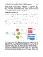
Fig. 12. Conceptual design of a CPR medical robot system.
9.2 Conceptual design of a CPR robot system
A conceptual design of the medical robot system is illustrated in Fig. 12. As shown in the
figure, the patient is placed on a bed beside a CPR robot which is mounted on a separated
movable base via two supporting columns and is placed above the chest of the patient. The
movable base can be moved anywhere on the ground and the supporting columns are
extensible in the vertical direction. Thus, the robot can be positioned well by hand so that
the chest compressions may start as soon as possible, which also allows a doctor to easily
take the robot away from the patient in case of any erroneous operation. Moreover, the CPR
robot is located on one side of the patient, thereby providing a free space for a rescuer to
access to the patient on the other side.
In view of the high stiffness and high accuracy properties, parallel mechanisms are
employed to design such a manipulator applicable to chest compressions in CPR. This idea
is motivated from the reason why the rescuer uses two hands instead of only one hand to
perform the action of chest compressions. In the process of performing chest compressions,
the two arms of the rescuer construct similarly a parallel mechanism. The main
disadvantage of parallel robots is their relatively limited workspace range. Fortunately, by a
proper design, a parallel robot is able to satisfy the workspace requirement with a height of
4–5 centimeters for the CPR operation.
In the next step, it comes with the problem of how to select a particular parallel robot for the
application of CPR since nowadays there exist a lot of parallel robots providing various
types of output motions. An observation of the chest compressions in manual CPR reveals
that the most useful motion adopted in such an application is the back and forth translation
in a direction vertical to the patient’s chest, whereas the rotational motions are almost
Parallel Manipulators, New Developments
478
useless. Thus, parallel robots with a total of six DOF are not necessary required here.
Besides, a 6-DOF parallel robot usually possesses some disadvantages in terms of
complicated forward kinematics problems and highly-coupled translation and rotation
motions, etc., which complicate the control problem of such kind of robot. Hence, TPMs
with only three translational DOF in space are sufficient to be employed in CPR operation.
Because in addition to a translation vertical to the chest of the patient, a 3-DOF TPM can also
provide translations in any other directions, which enables the adjustment of the
manipulator’s moving platform to a suitable position to perform chest compression tasks. At
this point, TPMs with less than three DOF are not adopted here.
As far as a 3-DOF TPM is concerned, it can be designed as various architectures with
different mechanical joints. Here, we adopt the type of TPMs whose actuators are mounted
on the base, since this property enables large powerful actuators to drive relatively small
structures, facilitating the design of the manipulator with faster, stiffer, and stronger
characteristics. In addition, from the economic point of view, the simpler of the architecture
of a TPM is, the lower cost it will be spent. In view of the complexity of the TPM topology
including the number of mechanical joints and links and their manufacture procedures, the
proposed 3-PCR TPM is chosen to develop a CPR medical robot. It should be noted that,
theoretically, other architectures such as the Delta or linear Delta like TPMs can be
employed in a CPR robot system as well.
10. Structure variations of a 3-PCR TPM
The three guide ways of a 3-PCR TPM can be arranged in other schemes to generate various
kinds of TPMs. For example, a 3-PCR TPM with an orthogonal structure is shown in Fig. 13.
The orthogonal 3-PCR TPM has a cubic shape workspace as illustrated in Fig. 14. Moreover,
the TPM has a partially decoupled translational motion. Hence, the orthogonal 3-PCR TPM
has a potentially wider application than the former one, especially in micro/nano scale
manipulation fields.
Fig. 13. A 3-PCR TPM with orthogonal guide ways.
Design, Analysis and Applications of a Class of New 3-DOF Translational Parallel Manipulators
479
Fig. 14. Workspace determination for an orthogonal 3-PCR TPM.
Fig. 15. A micro 3-PCR TPM designed for micro/nano manipulation.
For instance, a 3-PCR parallel micro-manipulator designed for ultrahigh precision
manipulation is shown in Fig. 15. The flexure hinges are adopted due to their excellent
characteristics over traditional joints in terms of vacuum compatibility, no backlash
property, no nonlinear friction, and simple structure and easy to manufacture, etc. Besides,
in view of greater actuation force, higher stiffness, and faster response characteristics of
piezoelectric actuators (PZTs), they are selected as linear actuators of the micro-manipulator.
Thanks to a high resolution motion, it is expected that the piezo-driven flexure hinge-based
parallel micro-manipulator can find its way into micro/nano scale manipulation.
11. Conclusion
In this chapter, a new class of translational parallel manipulator with 3-PCR architecture has
been proposed. It has been shown that such a mechanism can act as an overconstrained 3-
DOF translational manipulator with some certain assembling conditions satisfied. Since the
Parallel Manipulators, New Developments
480
proposed 3-PCR TPMs possess smaller mobile platform size than the corresponding 3-PRC
ones, they have wider application such as the rapid pick-and-place operation over a limited
space, etc.
The inverse and forward kinematics, velocity equations, and singular and isotropic
configurations have been derived. And the singularities have been eliminated from the
manipulator workspace by a proper mechanism design. The reachable workspace is
generated by an analytical as well as a numerical way, and the dexterity performances of the
TPM have been investigated in detail. As a new application, the designed 3-PCR TPM has
been adopted as a medical robot to assist in CPR. Furthermore, another 3-PCR TPM with
orthogonally arranged guide ways has been presented as well, which possesses a partially
decoupled motion within a cubic shape workspace and its application in micro/nano scale
ultrahigh precision manipulation has been exploited by virtue of flexure hinge-based joints
and piezoelectric actuation. Several virtual prototypes of the 3-PCR TPM are graphically
shown for the purpose of illustrating their different applications.
The results presented in the chapter will be valuable for both the design and development of
a new class of TPMs for various applications.
12. References
Angeles, J. (2005). The degree of freedom of parallel robot: A group-theoretic approach.
Proceedings of IEEE International Conference on Robotics and Automation, pp. 1005-
1012, Barcelona, Spain, Apr. 2005.
Bankman, I. N.; Gruben, K. G.; Halperin, H. R.; Popel, A. S.; Guerci, A. D. & Tsitlik, J. E.
(1990). Identification of dynamic mechanical parameters of the human chest during
manual cardiopulmonary resuscitation, IEEE Transactions on Biomedical Engineering,
Vol. 37, No. 2, pp. 211–217, Feb. 1990, ISSN 0018-9294.
Callegari, M. & Tarantini, M. (2003). Kinematic analysis of a novel translational platform,
ASME Journal of Mechanical Design, Vol. 125, No. 2, pp. 308–315, June 2003, ISSN
1050-0472.
Chablat, D. & Wenger, P. (2003). Architecture optimization of a 3-DOF translational parallel
mechanism for machining applications, the Orthoglide, IEEE Transactions on
Robotics and Automation, Vol. 19, No. 3, pp. 403–410, June 2003, ISSN 1042-296X.
Clavel, R. (1988). DELTA, a fast robot with parallel geometry, Proceedings of 18th International
Symposium on Industrial Robots, pp. 91–100, Lausanne, Switzerland, 1988.
Di Gregorio, R. & Parenti-Castelli, V. (1999). Mobility analysis of the 3-UPU parallel
mechanism assembled for a pure translational motion, Proceedings of IEEE/ASME
International Conference on Advanced Intelligent Mechatronics, pp. 520–525, Atlanta,
Georgia, USA, Sep. 1999.
Gosselin, C. & Angeles, J. (1991). A global performance index for the kinematic optimization
of robotic manipulators, ASME Journal of Mechanical Design, Vol. 113, No. 3, pp.
220–226, Sep. 1991, ISSN 1050-0472.
Hunt, K. H. (1990). Kinematic Geometry of Mechanisms, Oxford University Press, ISBN
0198562330, New York.
Design, Analysis and Applications of a Class of New 3-DOF Translational Parallel Manipulators
481
Kim, D. & Chung, W. K. (2003). Kinematic condition analysis of three-DOF pure
translational parallel manipulators, ASME Journal of Mechanical Design, Vol. 125,
No. 2, pp. 323–331, June 2003, ISSN 1050-0472.
Kim, H. S. & Tsai, L.W. (2003). Design optimization of a Cartesian parallel manipulator,
ASME Journal of Mechanical Design, Vol. 125, No. 1, pp. 43–51, Mar. 2003, ISSN 1050-
0472.
Kong, X. & Gosselin, C. M. (2002). Kinematics and singularity analysis of a novel type of 3-
CRR 3-DOF translational parallel manipulator, International Journal of Robotics
Research, Vol. 21, No. 9, pp. 791–798, Sep. 2002, ISSN 0278-3649.
Kong, X. & Gosselin, C. M. (2004). Type synthesis of 3-DOF translational parallel
manipulators based on screw theory, ASME Journal of Mechanical Design, Vol. 126,
No. 1, pp. 83–92, Mar. 2004, ISSN 1050-0472.
Li, Y. & Xu, Q. (2005). Dynamic analysis of a modified DELTA parallel robot for
cardiopulmonary resuscitation, Proceedings of IEEE/RSJ International Conference on
Intelligent Robots and Systems, pp. 3371–3376, Edmonton, Alberta, Canada, Aug.
2005.
Li, Y. & Xu, Q. (2006). Kinematic analysis and design of a new 3-DOF translational parallel
manipulator, ASME Journal of Mechanical Design, Vol. 128, No. 4, pp. 729–737, Jul.
2006, ISSN 1050-0472.
Li, Y. & Xu, Q. (2007). Kinematic analysis of a 3-PRS parallel manipulator, Robotics and
Computer-Integrated Manufacturing, Vol. 23, No. 4, pp. 395-408, Aug. 2007, ISSN
0736-5845.
Merlet, J P. (2000). Parallel Robots, Kluwer Academic Publishers, ISBN 1402003854, London.
Tsai, L. W.; Walsh, G. C. & Stamper, R. E. (1996). Kinematics of a novel three dof
translational platform, Proceedings of IEEE International Conference on Robotics and
Automation, pp. 3446–3451, Minneapolis, Minnesota, USA, Apr. 1996.
Tsai, L. W. & Joshi, S. (2002). Kinematics analysis of 3-DOF position mechanisms for use in
hybrid kinematic machines, ASME Journal of Mechanical Design, Vol. 124, No. 2, pp.
245–253, Jun. 2002, ISSN 1050-0472.
Xu, Q. & Li, Y. (2007). Design and analysis of a new singularity-free three-prismatic-
revolute-cylindrical translational parallel manipulator, Proceedings of The Institution
of Mechanical Engineers Part C-Journal of Mechanical Engineering Science, Vol. 221, No.
5, pp. 565–577, May 2007, ISSN 0954-4062.
Zhao, J S.; Zhou, K. & Feng, Z J. (2004). A theory of degrees of freedom for mechanisms.
Mechenism and Machine Theory, Vol. 39, No. 6, pp. 621–643, June 2004, ISSN 0094-
114X.
Zhao, T. S. & Huang, Z. (2000). A novel three-DOF translational platform mechanism and its
kinematics, Proceedings of ASME Design Engineering Technical Conferences &
Computers and Information in Engineering Conference, paper number
DETC2000/MECH-14101, Baltimore, Maryland, USA, Sep. 2000.
Parallel Manipulators, New Developments
482
Zlatanov, D.; Bonev, I. A. & Gosselin, C. M. (2002). Constraint singularities of parallel
mechanisms, Proceedings of IEEE International Conference on Robotics and Automation,
pp. 496–502, Washington D.C., USA, May 2002.
25
Type Design of Decoupled Parallel Manipulators
with Lower Mobility
Weimin Li
School of Mechanical Engineering, Hebei University of Technology
P. R. China
1. Introduction
A typical parallel mechanism consists of a moving platform, a fixed base, and several
kinematical chains (also called the legs or limbs) which connect the moving platform to its
base. Only some kinematical pairs are actuated, whose number usually equals to the
number of degrees of freedom (dofs) that the platform possesses with respect to the base.
Frequently, the number of legs equals to that of dofs. This makes it possible to actuate only
one pair per leg, allowing all motors to be mounted close to the base. Such mechanisms
show desirable characteristics, such as large payload and weight ratio, large stiffness, low
inertia, and high dynamic performance. However, compared with serial manipulators, the
disadvantages include lower dexterity, smaller workspace, singularity, and more noticeable,
coupled geometry, by which it is very difficult to determine the initial value of actuators
while the end effector stands at its original position.
In an engineering point of view, it is always important to develop a simple and efficient
original position calibration method to determine initial values of all actuators. This
calibration method usually becomes one of the key techniques that a type of mechanism can
be simply and successfully used to the precision applications. Accordingly, few have been
reported that the parallel manipulators being applied to high precision situations except
micro-movement ones.
The study of movement decoupling for parallel manipulators shows an opportunity to
simply the original position calibration and to improve the precision of parallel
manipulators in a handy way. One of the most important things in the study of movement
decoupling of parallel manipulators is how to design a new type with decoupled geometry.
Decoupled parallel manipulators with lower mobility (LM-DPMs) are parallel mechanisms
with less than six dofs and with decoupled geometry. This type of manipulators has
attracted more and more attention of academic researchers in recent years. Till now, it is
difficult to design a decoupled parallel manipulator which has translational and rotational
movement simultaneously (Zhang et al., 2006a, 2006b, 2006c). Nevertheless, under some
rules, it is relatively easy to design a decoupled parallel manipulator which can produce
pure translational (Baron & Bernier, 2001; Carricato, & Parenti-Castelli, 2001a; Gao et al.,
2005; Hervé, & Sparacino, 1992; Kim & Tsai, 2003; Kong & Gosselin, 2002; Li et al., 2005a,
2005b, 2006a; Tsai, 1996; Tsai et al., 1996; Zhao & Huang, 2000) or rotational (Carricato &
Parenti-Castelli, 2001b, 2004; Gogu, 2005; Li et al., 2006b, 2007a, 2007b) movements.
Parallel Manipulators, New Developments
484
This chapter attempts to provide a unified frame for the type design of decoupled parallel
manipulators with pure translational or rotational movements.
The chapter starts with the introduction of the LM-DPMs, and then, introduce a general idea
for type design. Finally, divide the specific subjects into two independent aspects, pure
translational and rotational. Each of them is discussed separately. Special attention is paid to
the kinds of joins or pairs, the limb topology, the type design, and etc.
2. The general idea for decoupled parallel manipulators with lower mobility
The general idea for the type design of decoupled parallel manipulators with lower mobility
can be expressed as the following theory.
Theory: A movement is independent with others if one of the following conditions is
satisfied:
(1) To the pure translational mechanisms, the translational actuator is orthogonal with the
plane composed of other translational actuators.
(2) To the pure rotational mechanisms (spherical mechanisms), the translational actuator is
parallel with the axis of rotational actuator.
Depend on part (1) of the theory, we can design some kinds of 3-dofs pure translational
decoupled parallel manipulators. Also we can get some kinds of 2-dofs spherical mechanism
based on part (2) of the theory.
For the convenience, first, let us define some letters to denote the joints (or pairs). They are
the revolute joint (R), the spherical joint (S), the prismatic pair (P), and the planar pair or flat
pair (F). They possess one revolute dof, three revolute dofs, one translational dof and three
dofs (two translational and one revolute) respectively. Then the theory can be expressed by
figure 1 and figure 2 separately.
Figure 1 illustrates the limb topology. The actuator should be installed with the prismatic
pair. The flat pair can be composed in deferent way. Using this kind of limb, we can design
some kinds of 3-dofs pure translational decoupled parallel manipulators.
x
y
z
Flat pair (F)
Prismatic pair (P)
Fig. 1. The idea for limb which can be used to compose decoupled translational mechanisms
Figure 2(a) illustrates the general one geometry of a decoupled 2-dofs spherical mechanism.
The moving platform is anchored to the base by two legs. A leg consists of two revolute
joints, R
1
and R
2
, whose axes, z
1
and z
2
, intersect at point o and connect to each other
perpendicularly to form a universal joint; so the value of
α
is π/2. The other leg consists of a
revolute joint, R
3
, a flat pair, F, and a prismatic pair P, in which the moving direction of P is
perpendicular to the working plane of F and the axis of R
3
. The revolute joints R
2
and R
3
are
mounted on the moving platform in parallel. The prismatic pair P and the revolute joint R
1
are assembled to the base, in which the moving direction of P is parallel to the axis of R
1
.
Type Design of Decoupled Parallel Manipulators with Lower Mobility
485
Suppose that the input parameters, q
1
and q
2
, represent the positions of the revolute joint R
1
and the prismatic pair P, which are driven by a rotary actuator and a linear actuator
separately. The pose of the moving platform is defined by the Euler angles
θ
1
and
θ
2
of the
platform. When the value of q
1
changes and q
2
holds the line, only
θ
1
alters. On the other
hand, when the value of q
2
changes, only
θ
2
changes. So,
θ
1
and
θ
2
are independently
determined by q
1
and q
2
respectively, i.e., one output parameter only relates to one input
parameter. In other words, the platform rotations around two axes are decoupled.
Figure 2(b) is an improved idea of figure 2(a). Using this idea, we can get a decoupled 2-
dofs spherical mechanism with a hemi-sphere work space.
o
z
1
z
2
θ
1
=
q
1
q
2
θ
2
α =π /2
Moving platfor
m
Base
F
R
1
P
R
2
R
3
e
Base
z
1
θ
2
α
Moving platform
z
2
R
2
R
1
R
3
S
o
P
q
2
e
m
θ
1
=
q
1
z
3
(a) (b)
Fig. 2. The idea for decoupled 2-dof spherical mechanisms
3. Design of 3-dofs translational manipulators with decoupled geometry
3.1 Type design
The Type design of 3-dofs translational manipulators is based on the analysis of limb
topology shown in figure 1.
(a) flat pair (3R, PPR, RPR) (b) prismatic pair (4R)
Fig. 3. The substitutes for the flat pair and the prismatic pair
Firstly, we construct deferent structures to replace the flat pair and the prismatic pair. Some
substitutes for the flat pair and the prismatic pair are shown in figure 3. Then, using the
pairs to form variational kinds of limbs. Figure 4 shows three examples. Finally, we can
constitute the 3-dofs translational manipulators by installing the specified limbs in
orthogonal as shown in figure 5, 6 and 7.
Parallel Manipulators, New Developments
486
(a) PPP (b) 7R (c) Modified 7R
Fig. 4. The examples of limbs
x
y
z
z
A
x
A
y
A
A
2
a
21
a
22
A
3
A
1
M
13
B
1
B
2
B
3
M
12
M
11
a
11
a
12
a
31
a
32
l
21
l
11
l
12
l
10
l
13
b
1
b
2
b
3
l
22
l
20
l
23
M
33
M
21
M
22
M
23
M
31
M
32
l
31
l
32
l
30
l
33
P
o
x
B
y
B
z
B
(a) Structure (b) Geometry
Fig. 5. 3-PPP manipulator
x
y
z
z
A
x
A
y
A
A
1
M
11
θ
1
θ
2
θ
3
M
12
M
13
B
1
l
11
l
12
l
13
A
2
M
21
M
22
l
21
l
22
l
23
M
23B
2
B
3
l
33
l
32
A
3
l
31
M
31
M
32
M
33
z
B
x
B
y
B
o
P
a
01
a
03
a
02
A
1
'
A
2
'
A
3
'
l
21
'
l
11
'
l
31
'
M
21
'
M
11
'
M
31
'
(a) Structure (b) Geometry
Fig. 6. 3-7R manipulator
Type Design of Decoupled Parallel Manipulators with Lower Mobility
487
x
y
z
z
A
y
A
x
A
a
01
a
02
a
03
A
1
M
11
M
11
'
M
12M
12
'
M
13
M
14
l
11
l
12
θ
1
θ
2
θ
3
M
21
M
21
'
M
22
M
22
'
l
21
l
22
M
23
M
24
M
34
A
2
A
3
M
31
M
31
'
M
32
'
M
32
M
33
l
31
l
32
z
B
x
B
p
y
B
o
(a) Structure (b) Geometry
Fig. 7. Modified 3-7R manipulator
3.2 Kinematics
The forward and inverse kinematic analyses for the 3-PPP manipulator shown in figure 5
are trivial since there exists a one-to-one correspondence between the moving platform
position and the input pair displacements. So the velocity jacobia matrix is a 3×3 identity
matrix.
The kinematics of 3-7R manipulator can be analysed as follows. Referring to figure 6(b),
each limb constrains point P to lie on a plane which passes through points M
j2
, M
j3
, and B
j
,
and is perpendicular to the axis of x, y, and z, respectively. The position of j
th
plane is
determined only by
θ
j
whenever the length l
j1
is given. Consequently, the position of P is
determined by the intersection of three planes, i.e., the intersection of
θ
j
for j=1,2,3. If the
distance from M
j1
to M
j2
is m
0j
, then a simple kinematic relation can be written as
01 01 11 1
02 02 21 2
03 03 31 3
sin
sin
sin
x
y
z
paml
paml
paml
θ
θ
θ
++
⎡
⎤⎡ ⎤
⎢
⎥⎢ ⎥
=++
⎢
⎥⎢ ⎥
⎢
⎥⎢ ⎥
−+ +
⎣
⎦⎣ ⎦
(1)
where p=[p
x
p
y
p
z
]
T
denotes the position vector of the end-effector. Taking the time
derivative of equation (1) yields
1
1
2
3
x
y
z
p
Jp
p
θ
θ
θ
−
⎡⎤
⎡
⎤
⎢⎥
⎢
⎥
=
⎢⎥
⎢
⎥
⎢⎥
⎢
⎥
⎣
⎦
⎣⎦
(2)
where J is a diagonal matrix that holds
Parallel Manipulators, New Developments
488
11 1
21 2
31 3
cos
cos
cos
l
Jl
l
θ
θ
θ
⎡
⎤
⎢
⎥
=
⎢
⎥
⎢
⎥
⎣
⎦
(3)
The kinematics of the modified 3-7R manipulator are the same.
3.3 Original position calibration
The calibration of 3-PPP manipulator is the same as a pure translational 3-dofs serial
manipulator. So we just consider the manipulator of 3-7R and modified 3-7R, they can be
expressed in the same way as shown in figure 8(a).
θ
0j
θ
s
θ
s
l
0
l
l
j1
u
θ
0j
π
/3
l
0
l
θ
0j
π
/3
l
j1
u
l
j1
(a) (b)
Fig. 8. Original position calibration
For convenience, we suppose,
(1) The input
θ
j
(j=1,2,3) is within [-
θ
jm
,
θ
jm
], where
θ
jm
>0, and
θ
j
=
θ
jm
denotes the initial
position of the j
th
limb;
(2) In the initial position (see figure 8), the angle between the link l
j1
(j=1,2,3) and the axis
u(u=x,y,z) is
θ
0j
(j=1,2,3).
Then the initial value
θ
jm
of
θ
j
can be determined as
0
2
j
m
j
π
θ
θ
=−
(4)
So we can determine
θ
0j
first, then
θ
jm
, the steps of the calibration can be as follows. From the
initial position
θ
0j
of the arm in figure 8, rotate the driving arm twice in a specified angle
θ
s
,
which satisfies
0
2
sj
θ
θπ
+
≤ (5)
During the process, record the two moving distances l
0
and l of the platform in the direction
of axis u(u=x,y,z), they satisfy
101 0 0
101 0 0
cos cos( )
cos cos( 2 )
jjj js
jjj js
ll l
ll ll
θθθ
θθθ
−+=
⎧
⎪
⎨
−
+=+
⎪
⎩
(6)
Type Design of Decoupled Parallel Manipulators with Lower Mobility
489
expand
0
cos( )
j
s
θ
θ
+ and
0
cos( 2 )
j
s
θ
θ
+
in equation (6),and eliminate
0
sin
j
θ
,we get
00
0
1
2cos
cos
2(1cos)
s
j
js
ll l
l
θ
θ
θ
+−
=
−
(7)
If
0
/3
θπ
≤ and let /3
θ
π
=
, then equation (7) yields
0
1
cos
j
j
l
l
θ
= (8)
The geometric signification of the equation (8) is shown in figure 8(b), which is very
sententious and convenient to industrial applications.
j
m
θ
can be get from equation (4).
3.4 Singularity
The 3-PPP manipulator has no singularity, so we just discuss the manipulator of 3-7R and
modified 3-7R, they can be expressed in the same.
From equation (2) we can find out that the rotational actuator speed is nonlinear to the
velocity of the end-effector. Moreover, if 90
j
θ
=
±°, then det 0J
=
, for any expected velocity
of the end-effector, the rotational speed of the actuator will be infinite. When
j
θ
is not equal
but close to 90±°, then
det 0J →
, the required rotational speed of the actuator may be still
too high to reach. So the value of the
j
θ
must be designed in an appropriate range
whenever the speed limit of the end-effector is given.
Suppose the desired velocity of the end-effector is
e
v , and the permissible rotational speed
of the actuator is
e
n
, then the absolute maximum value of the
j
θ
for
1,2,3j =
can be
obtained from equation (2), that is
1
cos
e
j
j
e
v
ln
θ
=
(9)
Let
1
arccos
e
jm
j
e
v
ln
θ
= (10)
Then
j
θ
should satisfy
j
m
jj
m
θ
θθ
−
≤≤ (11)
Whenever the mechanism design satisfies equation (11), no singularity will exist.
4. Design of 2-dofs spherical manipulators with decoupled geometry
4.1 Type Design
The Type design of 2-dofs spherical manipulators is based on the general idea shown in
figure 2. Using the 3R and 4R pairs in figure 3 to replace the F and P pairs separately, a new
Parallel Manipulators, New Developments
490
structure (2R&8R manipulator) for figure 2(a) is constructed as shown in figure 9. Similarly,
figure 10 shows the improved configuration of figure 2(b), a 2R&PRR manipulator, but
distinguishingly, additional modification is that a through hole is added to the center of the
revolute joint R
1
, so the prismatic pair P can be set in the center of the hole and rotates with
R
1
. As a result, the workspace of
θ
1
can reach 2
π
.
e
m
z
1
z
2
q
1
q
2
θ
1
R
1
R
2
R
3
R
4
R
5
R
6
R
7
R
8
R
9
R
10
θ
2
P
Base
Moving platfor
m
o
Fig. 9. 2R&8R manipulator
Base
z
1
θ
2
Moving platform
z
2
R
2
R
3
P
e
m
q
2
R
1
z
3
θ
1
Seeing from z
2
P
R
3
R
2
R
1
e
m
q
2
θ
2
z
1
z
3
R
4
R
4
Fig. 10. 2R&PRR manipulator
4.2 Kinematics
Firstly, the 2R&8R manipulator in figure 9 will be discussed. Let e be the distance between
the axes of R
2
and R
3
, m be the distance between the axes of R
8
and R
10
(or R
7
and R
9
). Also,
suppose that, when the moving platform is on the initial position, the axis of R
1
is
perpendicular to the plane consisting of the axes of R
2
and R
3
. Then the displacement
relationships between input and output for the 2R&8R manipulator are:
Type Design of Decoupled Parallel Manipulators with Lower Mobility
491
11
22
sin sin
q
mqe
θ
θ
=
⎧
⎨
=
⎩
(12)
In the structure design, it is easy to set the length m of
79
RR and
810
RR equal to the distance
e between the axes of R
2
and R
3
so as to get the one-to-one input-output mapping. Let m = e,
it follows that:
11
22
q
q
θ
θ
=
⎫
⎬
=
⎭
(13)
This implies that the direct linear one-to-one input-output correlation, so the velocity jacobia
matrix becomes an identity one.
Now we discuss the the 2R&PRR manipulator shown in figure 10. Suppose that the input
parameters, q
1
and q
2
, represent the angular displacement of the revolute joint R
1
and the
distance between the axes of R
2
and R
4
separately. They are driven by a rotary actuator and
a linear actuator. The pose of the moving platform is defined by the Euler angles
θ
1
and
θ
2
of
the platform. Let e be the distance between the axes of R
2
and R
3
, m be the distance between
the axes of R
3
and R
4
. Also suppose that, axis z
3
is through the point o and always
perpendicular to the plane of z
1
-z
2
and moreover, define the value of
θ
2
is zero whenever the
axis of R
3
is on the plane of z
1
-z
2
. Then the coordinates of R
4
and R
3
for the axes z
1
and z
3
are
413 42
313 3 2 2
(,) (,0)
( , ) ( cos , sin )
Rzz Rq
Rzz Re e
θ
θ
=
⎧
⎨
=
⎩
(14)
The displacement relationship between input and output is:
11
222 2
22 2
(cos)sin
q
qe e m
θ
θθ
=
⎧
⎨
−+=
⎩
(15)
Taking the derivative of equation (15), it follows that
1
1
1
2
2
q
J
q
θ
θ
−
⎡
⎤
⎡⎤
=
⎢
⎥
⎢⎥
⎣⎦
⎣
⎦
(16)
Where,
22
22
10
sin
0
cos
J
eq
eq
θ
θ
⎡
⎤
⎢
⎥
=
⎢
⎥
⎢
⎥
⋅−
⎣
⎦
(17)
4.3 Singularity and workspace
The 2R&8R manipulator shown in figure 9 has two legs. The first leg (R
1
to R
2
) produces the
Euler angle
θ
1
of the platform by the input of q
1
; while the second one (R
10
to R
3
) produces
θ
2
by q
2
. To illustrate the motional relationship, let us introduce a transition parameter z to
equation (12), it follows that:
Parallel Manipulators, New Developments
492
11
22
sin sin
q
mqze
θ
θ
=
⎧
⎨
==
⎩
(18)
where, z is the displacement of F-pair (R
4
to R
6
) in the direction of z
1
.
From equation (18), it is seen that the Euler angle
θ
1
is produced from the input of q
1
directly
by the first leg; while
θ
2
is produced from q
2
by the second leg through two transformations,
which include (1) rotary to linear motion
2
qz⇒
using
2
sinmqz
⋅
=
, and (2) linear to rotary
motion
2
z
θ
⇒ using
2
sinze
θ
=
⋅ . In the second transformation, there exists a limitation
related to friction circle. Let
ρ
denote the radius of the friction circle of R
2
, which is
determined by the product of the radius r of the revolute joint’s axis and the equivalent
friction coefficient
μ
as follows.
r
ρ
μ
=
(19)
γ
e
z
1
R
2
M
Q
F
F
r
F
t
R
3
Fig. 11. Force and torque of R
2
Let
γ
denote the angle between z
1
and the link
23
RR
, and decompose the force F into two
parts, the radial component F
r
and the tangent component F
t
(see figure 11). Then the force F
acts on R
2
is equivalent to a force Q and a torque M, which can be calculated from the
following equations.
cos
sin
r
t
QF F
MFeFe
γ
γ
==⋅
⎫
⎬
=⋅=⋅⋅
⎭
(20)
As a basic law in mechanics, the effect of a force Q and a torque M acting on a rigid body is
equivalent to a force Q
h
with an offset h, which is shown in figure 12 and can be calculated
as follows
/tan
h
hMQe
γ
=
⎫
⎬
==⋅
⎭
(21)
where, h is the distance between the action lines of force Q
h
and Q.
Type Design of Decoupled Parallel Manipulators with Lower Mobility
493
M
Q
Q
h
action line of Q
h
equivalent to
p
p
Fig. 12. Force couple equivalent
There exist three instances for the different relationship between h and
ρ
, which are (1) h <
ρ
,
the revolute joint R
2
will never rotate regardless the value of Q
h
; (2) h >
ρ
, revolute joint R
2
can rotate; and (3) h =
ρ
, the critical condition. In the critical condition of h =
ρ
, using
equation (21), it follows that:
(
)
arctan / e
γρ
=
(22)
Then the workspace of
θ
2
satisfies:
2
(/2 ) /2
π
γθπ γ
−
−<< − (23)
On the other hand, the angle
θ
1
produced by the first leg is limited only by the structure
design of the F-pair and the base, so the workspace of
θ
1
can reach a designated area
through proper design. Assume that the workspace of
θ
1
is from – π/2 to π/2, then the
workspace of the spherical mechanism can be depicted by the reachable range of the point P
as shown in figure 13. The workspace is smaller than a hemisphere, so it would be limitted
in some applications.
When the mechanism is running, the direction of axis z
1
keeps unchanged, while the
direction of axis z
2
alters according to
θ
1
. So the workspace represented by spherical surface
in figure 13 can be interpreted as follows: point P draws latitude lines when only
θ
1
changes
and draws longitude lines while only
θ
2
alters.
z
1
z
2
θ
1
θ
2
γ
P
Fig. 13. The workspace denoted by the locus of point P
Parallel Manipulators, New Developments
494
Now we examine the 2R&PRR manipulator in figure 10. The only limitation of this
mechanism is caused by the friction circle of R
2
. This limitation can be described by figure
14, from which we can see that the work space of
2
θ
satisfies
2min 2 2max
θθθ
<<
(24)
Where
2min
θ
and
2max
θ
are the minimum and the maximum boundaries, which can be
simply calculated based on figure 14 as follows
2min
2222
arcsin 0
()
m
eem
ρ
θ
ρρ
=
>
+−+
(25)
22 22
2max
arctan arctan 2
me e
ρρ
θ
π
ρρ
−− −
=+< (26)
P
R
3
R
2
R
1
e
m
q
2
θ
2
z
1
z
3
R
4
P
R
3
R
2
R
1
z
1
z
3
R
4
ρ
P
R
3
R
2
R
1
z
1
z
3
R
4
ρ
θ
2min
θ
2max
Fig. 14. Workspace of
2
θ
limited by friction circle of R
2
It means that the workspace of the mechanism can not reach a hemisphere. Clearly, this is
not desirable.
In fact, because the workspace of
1
θ
is [0, 2
π
], the mechanism workspace can reach a
hemisphere only if the workspace of
2
θ
is chosen [0,
π
/2] or [
π
/2,
π
]. So there exist two
methods to get a hemisphere workspace.
Figure 15 shows the critical instances for both of them; each one uses the similar technique
to offset the axis of R
4
from the axis z
1
. Let n denotes the axis offset of R
4
(or the length of
AR
4
), and n
c
is the special value of n for the critical configurations as shown in figure 15,
then n should be chosen equation (27). Using this technique, a hemisphere work space can
be obtained.
c
m
nn
e
ρ
>=
(27)
Type Design of Decoupled Parallel Manipulators with Lower Mobility
495
P
R
3
R
2
R
1
z
1
z
3
R
4
ρ
A
B
P
R
3
R
2
R
1
z
1
z
3
R
4
ρ
A
B
Fig. 15. Two methods to modify the boundaries of
2
θ
: (a)
2min
0
θ
=
, (b)
2max
2
θ
π
=
Base
z
1
θ
2
Moving platform
z
2
R
2
R
3
P
e
m
q
2
R
1
z
3
θ
1
R
4
A
n
Seeing from z
2
P
R
3
R
2
R
1
e
m
q
2
θ
2
z
1
z
3
R
4
A
n
Fig. 16. The improved mechanism for
2
[0, /2]
θ
π
∈
The improved architectures are shown in figure 16 and figure 17, in which the workspace of
2
θ
includes the area of [0,
π
/2] or [
π
/2,
π
] separately.
A prototype model of the mechanism for the condition of
2
[0, /2]
θ
π
∈
is designed. Figure
18 shows the outline picture of this model. In this design, one leg is actuated by a servo
motor through a tooth belt; while the other leg is actuated by the other servo motor through