CCNA: Fast Pass phần 9 pot
Bạn đang xem bản rút gọn của tài liệu. Xem và tải ngay bản đầy đủ của tài liệu tại đây (564.5 KB, 39 trang )
296
Chapter 4
Technology
Logical Link Control (LLC) 802.2 This sublayer is responsible for identifying Network layer
protocols and then encapsulating them. An LLC header tells the Data Link layer what to do
with a packet once a frame is received. It works like this: a host receives a frame and looks in
the LLC header and finds out that the packet is destined for, say, the IP protocol at the Network
layer. The LLC can also provide flow control and sequencing of control bits.
Data-link layer devices
Switches and bridges both work at the Data Link layer and filter the network using hardware
(MAC) addresses. Layer 2 switching is considered hardware-based bridging because it uses spe-
cialized hardware called an application-specific integrated circuit (ASIC). ASICs can run up to
gigabit speeds with very low latency rates.
Latency is the time measured from when a frame enters a port to the time it
exits.
Bridges and switches read each frame as it passes through the network. The Layer 2 device
then puts the source hardware address in a filter table and keeps track of which port the frame
was received on. This information (logged in the bridge’s or switch’s filter table) is what helps
the machine determine the location of the specific sending device.
The real estate business is all about location, location, location, and it’s the same way for both
Layer 2 and 3 devices. Though both need to be able to negotiate the network, it’s crucial to
remember that they’re concerned with very different parts of it. Primarily, routers, or Layer-3
machines, need to locate specific networks, whereas Layer 2 machines (switches and bridges) need
to locate specific devices. So, networks are to routers as individual devices are to switches and
bridges. And routing tables that “map” the internetwork are for routers, as filter tables that
“map” individual devices are for switches and bridges.
After a filter table is built on the Layer 2 device, it will only forward frames to the segment
where the destination hardware address is located. If the destination device is on the same seg-
ment as the frame, the Layer 2 device will block the frame from going to any other segments.
If the destination is on a different segment, the frame can only be transmitted to that segment.
This is called transparent bridging.
When a switch interface receives a frame with a destination hardware address that isn’t
found in the device’s filter table, it will forward the frame to all connected segments. If the
unknown device that was sent the “mystery frame” replies to this forwarding action, the switch
updates its filter table regarding that device’s location. But if the destination address of the
transmitting frame is a broadcast address, the switch forwards all broadcasts to every connected
segment by default.
All devices that the broadcast is forwarded to are considered to be in the same broadcast
domain. This can be a problem; Layer 2 devices propagate Layer 2 broadcast storms that choke
performance, and the only way to stop a broadcast storm from propagating through an inter-
network is with a Layer 3 device—a router.
4309c04.fm Page 296 Thursday, October 23, 2003 4:51 PM
4.1 Describe Network Communications Using Layered Models
297
Using switches for Layer 2 segmentation
The biggest benefit of using switches instead of hubs in your internetwork is that each switch
port is actually its own collision domain. (Conversely, a hub creates one large collision domain.)
But even armed with a switch, you still can’t break up broadcast domains. Neither switches nor
bridges will do that. Typically, they’ll simply forward all broadcasts instead.
Another benefit of LAN switching over hub-centered implementations is that each device on
every segment plugged into a switch can transmit simultaneously—as long as there is only one
host on each port and the hub isn’t plugged into the switch port, which is another benefit of each
switch port being its own collision domain. As you might have guessed, hubs only allow one
device per segment to communicate at a time.
Each network segment connected to the switch must have the same type of devices attached.
This means that you can connect an Ethernet hub into a switch port and then connect multiple
Ethernet hosts into the hub, but you can’t mix Token Ring hosts in with the Ethernet gang on
the same segment. Mixing hosts in this manner is called media translation, and Cisco says
you’ve just got to have a router around if you need to provide this service. Although I have
found this not to be true in reality, remember, we’re studying for the CCNA exam here, right?
The Physical Layer
Finally arriving at the bottom, we find that the Physical layer does two things: it sends bits and
receives bits. Bits come only in values of 1 or 0—a Morse code with numerical values. The Physical
layer communicates directly with the various types of actual communication media. Different
kinds of media represent these bit values in different ways. Some use audio tones, while others
employ state transitions—changes in voltage from high to low and low to high. Each type of
media needs specific protocols to describe the proper bit patterns to be used, how data is encoded
into media signals, and the various qualities of the physical media’s attachment interface.
Physical layer in the WAN
The Physical layer specifies the electrical, mechanical, procedural, and functional requirements for
activating, maintaining, and deactivating a physical link between end systems. This layer is also
where you identify the interface between the data terminal equipment (DTE) and the data
communication equipment (DCE). (Some old phone company employees still call DCE data
circuit–terminating equipment.) The DCE is usually located at the service provider, while the
DTE is the attached device. The services available to the DTE are most often accessed via a
modem or channel service unit/data service unit (CSU/DSU).
Physical layer in the LAN
The Physical layer’s connectors and different physical topologies are defined by the OSI as
standards, allowing disparate systems to communicate. The CCNA exam is only interested in
the IEEE Ethernet standards.
Of the Ethernet devices at the physical layer, the only one we are concerned with is the hub.
A hub is really a multiple-port repeater. A repeater receives a digital signal, reamplifies or regen-
erates that signal, and then forwards it out all active ports without looking at any data. An
4309c04.fm Page 297 Thursday, October 23, 2003 4:51 PM
298
Chapter 4
Technology
active hub does the same thing. Any digital signal received from a segment on a hub port is
regenerated or reamplified and transmitted out all ports on the hub. This means all devices
plugged into a hub are in the same collision domain as well as in the same broadcast domain.
Hubs, like repeaters, don’t actually examine any of the traffic as it enters and is then trans-
mitted out to the other parts of the physical media. Every device connected to the hub, or hubs,
must listen to see if a device transmits. A physical star network—where the hub is a central
device and cables extend in all directions out from it—is the type of topology a hub creates.
Visually, the design really does resemble a star, whereas Ethernet networks run a logical bus
topology, meaning that the signal has to run from one end of the network to the other.
Exam Essentials
Remember the three layers in the Cisco three-layer model. The three layers in the Cisco hier-
archical model are the core, distribution, and access layers.
Remember the seven layers of the OSI model. You must remember the seven layers of the
OSI model and what function each layer provides. The Application, Presentation, and Session
layers are upper layers and are responsible for communicating between a user interface and an
application. The Transport layer provides segmentation, sequencing, and virtual circuits. The
Network layer provides logical network addressing and routing through an internetwork. The
Data Link layer provides framing and places data on the network medium. The Physical layer
takes ones and zeros and encodes them into a digital signal that it can transmit on the network
segment.
Remember the difference between connection-oriented and connectionless network services.
Connection-oriented uses acknowledgments and flow control to create a reliable session. More
overhead is used than in a connectionless network service. Connectionless services are used to
send data with no acknowledgments or flow control. This is considered unreliable.
4.2 Describe the Spanning Tree Process
Back before it was purchased and renamed Compaq, a company called Digital Equipment Cor-
poration (DEC) created the original version of Spanning Tree Protocol (STP). The IEEE later
created its own version of STP called 802.1D. All Cisco switches run the IEEE 802.1D version
of STP, which isn’t compatible with the DEC version.
STP’s main task is to stop network loops from occurring on your Layer 2 network (bridges
or switches). It vigilantly monitors the network to find all links, making sure that no loops occur
by shutting down any redundant ones. STP uses the spanning-tree algorithm (STA) to first
create a topology database, then search out and destroy redundant links. With STP running,
frames will only be forwarded on the premium, STP-picked links.
4309c04.fm Page 298 Thursday, October 23, 2003 4:51 PM
4.2 Describe the Spanning Tree Process
299
Spanning-Tree Terms
Before I get into describing the details of how STP works in the network, you need to under-
stand some basic ideas and terms and how they relate within the Layer 2 switched network:
STP Spanning Tree Protocol (STP) is a bridge protocol that uses the STA to find redundant
links dynamically and create a spanning-tree topology database. Bridges exchange Bridge Pro-
tocol Data Unit (BPDU) messages with other bridges to detect loops, and then remove them by
shutting down selected bridge interfaces.
Root bridge The root bridge is the bridge with the best bridge ID. With STP, the key is for all
the switches in the network to elect a root bridge that becomes the focal point in the network.
All other decisions in the network—like which port is to be blocked and which port is to be put
in forwarding mode—are made from the perspective of this root bridge.
BPDU All the switches exchange information to use in the selection of the root switch, as well
as for subsequent configuration of the network. Each switch compares the parameters in the
BPDU that they send to one neighbor with the one that they receive from another neighbor.
Bridge ID This is how STP keeps track of all the switches in the network. The bridge ID is
determined by a combination of the bridge priority (32,768 by default on all Cisco switches)
and the base MAC address. The lowest bridge ID becomes the root bridge in the network.
Nonroot bridge All bridges that are not the root bridge. These exchange BPDUs with all
bridges and update the STP topology database on all switches, preventing loops and providing
a measure of defense against link failures.
Root port Always the link directly connected to the root bridge, or the shortest path to the
root bridge. If more than one link connects to the root bridge, then a port cost is determined by
checking the bandwidth of each link. The lowest cost port becomes the root port.
Designated port Either a root port or a port that has been determined as having the best (lower)
cost—a designated port will be marked as a forwarding port.
Port cost Determined when multiple links are used between two switches and none are root
ports. The cost of a link is determined by the bandwidth of a link.
Nondesignated port Port with a higher cost than the designated port that will be put in blocking
mode—a nondesignated port is not a forwarding port.
Forwarding port Port that forwards frames.
Blocked port Port that will not forward frames in order to prevent loops. However, a blocked
port will always listen to frames.
Spanning-Tree Operations
As I’ve said before, STP’s job is to find all links in the network and shut down any redundant
ones, thereby preventing network loops from occurring. STP does this by first electing a root
4309c04.fm Page 299 Thursday, October 23, 2003 4:51 PM
300
Chapter 4
Technology
bridge that will preside over network topology decisions. Those decisions include determining
which “roads” are the best ones for frames to travel on normally, and which ones should be
reserved as backup routes if one of the primary “roads” fail.
Things tend to go a lot more smoothly when you don’t have more than one person making
a navigational decision, and so there can only be one root bridge in any given network. I’ll
discuss the root bridge election process more completely in the next section.
Selecting the Root Bridge
The bridge ID is used to elect the root bridge in the network as well as to determine the root
port. This ID is 8 bytes long and includes both the priority and the MAC address of the device.
The default priority on all devices running the IEEE STP version is 32,768.
To determine the root bridge, the priorities of the bridge and the MAC address are combined.
If two switches or bridges happen to have the same priority value, then the MAC address becomes
the tiebreaker for figuring out which one has the lowest (best) ID. It’s like this: if two switches—
I’ll name them A and B—both use the default priority of 32,768, then the MAC address will be
used instead. If switch A’s MAC address is 0000.0c00.1111 and switch B’s MAC address is
0000.0c00.2222, then switch A would become the root bridge. Just remember that the lower
value is the better one when it comes to electing a root bridge.
BPDUs are sent every 2 seconds, by default, out all active ports on a bridge/switch, and the
bridge with the lowest (best) bridge ID is elected the root bridge. You can change the bridge’s
ID so that it will become a root bridge automatically. Being able to do that is important in a
large switched network—it ensures that the best paths are chosen.
Changing STP parameters is beyond the scope of this book, but it’s covered in
the Sybex CCNP
®
: Building Cisco Multilayer Switched Networks Study Guide
(Sybex, 2004).
Selecting the Designated Port
If more than one link is connected to the root port, then port cost becomes the factor used to
determine which port will be the root port. So, to determine the port or ports that will be used
to communicate with the root bridge, you must first figure out the path’s cost. The STP cost is
an accumulated total path cost based on the available bandwidth of each of the links. Table 4.1
shows the typical costs associated with various Ethernet networks.
TABLE 4.1 Typical Costs of Different Ethernet Networks
Speed New IEEE Cost Original IEEE Cost
10Gbps 2 1
1Gbps 4 1
4309c04.fm Page 300 Thursday, October 23, 2003 4:51 PM
4.2 Describe the Spanning Tree Process
301
The IEEE 802.1D specification has recently been revised to handle the new higher-speed
links. The IEEE 802.1D specification assigns a default port cost value to each port based on
bandwidth.
Spanning-Tree Port States
The ports on a bridge or switch running STP can transition through five different modes:
Blocking A blocked port won’t forward frames; it just listens to BPDUs. All ports are in blocking
state by default when the switch is powered up. The purpose of the blocking state is to prevent the
use of looped paths.
Listening The port listens to BPDUs to make sure no loops occur on the network before passing
data frames. A port in listening state prepares to forward data frames without populating the
MAC address table.
Learning The switch port listens to BPDUs and learns all the paths in the switched network.
A port in learning state populates the MAC address table but doesn’t forward data frames.
Forwarding The port sends and receives all data frames on the bridged port.
Disabled A port in the disabled state does not participate in the frame forwarding or STP. A
port in the disabled state is virtually nonoperational.
Switch ports are most often in either the blocking or forwarding state. A forwarding port is
one that has been determined to have the lowest (best) cost to the root bridge. But when and if
the network experiences a topology change (because of a failed link or because someone adds
in a new switch), you’ll find the ports on a switch in listening and learning state.
As I said, blocking ports is a strategy for preventing network loops. Once a switch determines
the best path to the root bridge, then all other ports will be in blocking mode. Blocked ports can
still receive BPDUs—they just don’t send out any frames.
If a switch determines that a blocked port should now be the designated port, it will go into
listening mode and check all BPDUs it receives to make sure that it won’t create a loop once the
port goes to forwarding mode—nice!
Convergence
Convergence occurs when bridges and switches have transitioned to either the forwarding or
blocking modes. No data is forwarded during this time. Before data can be forwarded again,
all devices must be updated. Convergence is important to make sure all devices have the same
100Mbps 19 10
10Mbps 100 100
TABLE 4.1 Typical Costs of Different Ethernet Networks (continued)
Speed New IEEE Cost Original IEEE Cost
4309c04.fm Page 301 Thursday, October 23, 2003 4:51 PM
302
Chapter 4
Technology
database, but it does cost you some time. It usually takes 50 seconds to go from blocking to
forwarding mode, and I don’t recommend changing the default STP timers. (But you can
adjust those timers if necessary.)
Exam Essentials
Understand the states of STP. The purpose of the blocking state is to prevent the use of looped
paths. A port in listening state prepares to forward data frames without populating the MAC
address table. A port in learning state populates the MAC address table but doesn’t forward data
frames. The forwarding port sends and receives all data frames on the bridged port. Lastly, a port
in the disabled state is virtually nonoperational.
Understand the main purpose of the spanning tree in a switched LAN. The main purpose of
STP is to prevent switching loops in a network with redundant switched paths.
4.3 Compare and Contrast Key
Characteristics of LAN Environments
There have been several popular LAN technologies in the past, but the one that has emerged
dominant has been Ethernet. Although technologies such as Token Ring are still available, they
are not experiencing the development or expansion that Ethernet is. If there is a new kid on the
block, though, it has to be wireless technologies. In this section, we will first discuss Ethernet
networking, and then move on to cover LAN switching as it applies to Ethernet LANs. Finally,
we will take a quick look at some of the newest wireless LANs.
For purposes of preparing for the CCNA exam, we will confine our discussion
to Ethernet and wireless LANs.
Ethernet Networking
Ethernet is a contention media access method that allows all hosts on a network to share the
same bandwidth of a link. Ethernet is popular because it’s readily scalable, which means that it’s
comparatively easy to integrate new technologies, like FastEthernet and Gigabit Ethernet, into
an existing network infrastructure. It’s also relatively simple to implement in the first place, and
with it, troubleshooting is reasonably straightforward. Ethernet uses both Data Link and Phys-
ical layer specifications, and this section of the chapter will give you both the Data Link and
Physical layer information you need to effectively implement, troubleshoot, and maintain an
Ethernet network.
4309c04.fm Page 302 Thursday, October 23, 2003 4:51 PM
4.3 Compare and Contrast Key Characteristics of LAN Environments
303
Ethernet networking uses Carrier Sense Multiple Access with Collision Detect (CSMA/CD), a
protocol that helps devices share the bandwidth evenly without having two devices transmit at the
same time on the network medium. CSMA/CD was created to overcome the problem of those col-
lisions that occur when packets are transmitted simultaneously from different nodes. And trust
me, good collision management is crucial, because when a node transmits in a CSMA/CD net-
work, all the other nodes on the network receive and examine that transmission. Only bridges and
routers can effectively prevent a transmission from propagating throughout the entire network!
So, how does the CSMA/CD protocol work? Like this: when a host wants to transmit over
the network, it first checks for the presence of a digital signal on the wire. If all is clear (no
other host is transmitting), the host will then proceed with its transmission. But it doesn’t stop
there. The transmitting host constantly monitors the wire to make sure no other hosts begin
transmitting. If the host detects another signal on the wire, it sends out an extended jam signal
that causes all nodes on the segment to stop sending data (think, busy signal). The nodes
respond to that jam signal by waiting a while before attempting to transmit again. Backoff
algorithms determine when the colliding stations can retransmit. If collisions keep occurring
after 15 tries, the nodes attempting to transmit will then time out. Pretty clean!
The effects of having a CSMA/CD network sustaining heavy collisions include the following:
Delay
Low throughput
Congestion
Backoff on an 802.3 network is the retransmission delay that’s enforced when
a collision occurs.
Half- and Full-Duplex Ethernet
Half-duplex Ethernet is defined in the original 802.3 Ethernet and Cisco says you only use one
wire pair with a digital signal running in both directions on the wire. It also uses the CSMA/CD
protocol to help prevent collisions and to permit retransmitting if a collision does occur. If a hub
is attached to a switch, it must operate in half-duplex mode because the end stations must be
able to detect collisions. Half-duplex Ethernet—typically 10BaseT—is only about 30 to 40
percent efficient as Cisco sees it, because a large 10BaseT network will usually only give you
3- to 4Mbps—at most.
Full-duplex Ethernet uses two pairs of wires, instead of one wire pair like half duplex. Also,
full duplex uses a point-to-point connection between the transmitter of the transmitting device
and the receiver of the receiving device, which means that with full-duplex data transfer, you get
a faster data transfer compared to half duplex. And because the transmitted data is sent on a dif-
ferent set of wires than the received data, no collisions occur—sweet!
4309c04.fm Page 303 Thursday, October 23, 2003 4:51 PM
304
Chapter 4
Technology
The reason you don’t need to worry about collisions is because now Full-duplex Ethernet is like
a freeway with multiple lanes instead of the single-lane road provided by half duplex. Full-duplex
Ethernet is supposed to offer 100 percent efficiency in both directions; this means you can get
20Mbps with a 10Mbps Ethernet running full duplex, or 200Mbps for FastEthernet—woohoo!
But this rate is something known as an aggregate rate, which translates into “You’re supposed to
get” 100 percent efficiency. No guarantees in networking, as in life.
Full-duplex Ethernet can be used in three situations:
With a connection from a switch to a host
With a connection from a switch to a switch
With a connection from a host to a host using a crossover cable
Full-duplex Ethernet requires a point-to-point connection when only two nodes
are present.
Now, if it’s capable of all that speed, why won’t it deliver? Well, when a Full-duplex Ethernet
port is powered on, it first connects to the remote end, and then it negotiates with the other end
of the FastEthernet link. This is called an auto-detect mechanism. This mechanism first decides
on the exchange capability, which means it checks to see if it can run at 10 or 100Mbps. It then
checks to see if it can run full duplex, and if it can’t, it will run half duplex.
Remember that half-duplex Ethernet shares a collision domain and provides
a lower effective throughput than Full-duplex Ethernet, which typically has a
private collision domain and a higher effective throughput.
Ethernet at the Data Link Layer
Ethernet at the Data Link layer is responsible for Ethernet addressing, commonly referred to as
hardware addressing or MAC addressing. Ethernet is also responsible for framing packets
received from the Network layer and preparing them for transmission on the local network
through the Ethernet contention media access method.
Ethernet Addressing
Here’s where we get into how Ethernet addressing uses the MAC address burned into every
Ethernet NIC. The MAC, or hardware address, is a 48-bit (6 byte) address written in a hexa-
decimal format.
Figure 4.10 shows the 48-bit MAC addresses and how the bits are divided.
4309c04.fm Page 304 Thursday, October 23, 2003 4:51 PM
4.3 Compare and Contrast Key Characteristics of LAN Environments
305
FIGURE 4.10 Ethernet addressing using MAC addresses
The organizationally unique identifier (OUI) is assigned by the IEEE to an organization. It’s
composed of 24 bits, or 3 bytes. The organization, in turn, assigns a globally administered
address (24 bits, or 3 bytes) that is unique (supposedly—again, no guarantees) to every adapter
they manufacture. Look closely at the figure. The high-order bit is the Individual/Group (I/G)
bit. When it has a value of 0, you can assume the address is actually the MAC address of a device
and may well appear in the source portion of the MAC header. When it is a 1, you can assume
that the address represents either a broadcast or multicast address in Ethernet, or a broadcast
or functional address in Token Ring and FDDI (who really knows about FDDI?). The next bit
is the Global/Local (G/L) bit (also known as U/L, where U means Universal). When set to 0, this
bit represents a globally administered address (as by the IEEE). When the bit is a 1, it represents
an administratively locally governed address (as in DECnet). The low-order 24 bits of an
Ethernet address represent a locally (if anything) administered or manufacturer assigned
code. This portion commonly starts with 24 zeros (0s) for the first card made and continues
in order until there are 24 ones (1s) for the last (16,777,216th) card made. You’ll actually find
that many manufacturers use these same 6 hex digits as the last 6 characters of their serial
number on the same card.
Ethernet Frames
The Data Link layer is responsible for combining bits into bytes and bytes into frames. Frames
are used at the Data Link layer to encapsulate packets handed down from the Network layer
for transmission on a type of media access. There are three types of media access methods:
contention (Ethernet), token passing (Token Ring and FDDI), and polling (IBM Mainframes
and 100VG-AnyLAN).
100VG-AnyLAN is a twisted-pair technology that was the first 100Mbps LAN.
However, because it was incompatible with Ethernet signaling techniques (it
used a demand priority access method), it wasn’t very popular, and is now
essentially dead.
The function of Ethernet frames is to pass data between hosts using a group of bits known
as a MAC frame format. This provides error detection from a cyclic redundancy check (CRC).
But remember—this is error detection, not error correction.
Organizationally
Unique Identifier (OUI)
(Assigned by IEEE)
24 bits 24 bits
Vendor assignedI/GI/G
4647
4309c04.fm Page 305 Thursday, October 23, 2003 4:51 PM
306
Chapter 4
Technology
There are several ways to create Ethernet frames. Each way is called a frame type or frame
format, and has a unique name. The 802.3 frames and the Ethernet_II frame formats are shown
in Figure 4.11.
FIGURE 4.11 802.3 and Ethernet frame formats
Encapsulating a frame within a different type of frame is called tunneling.
The following points detail the different fields in the 802.3 and Ethernet_II frame types.
Preamble An alternating 1,0 pattern provides a 5MHz clock at the start of each packet, which
allows the receiving devices to lock the incoming bit stream.
Start Frame Delimiter (SFD)/Synch The SDF/Synch is in the last octet of the eight octet pre-
amble. The SFD is 10101011, where the last pair of ones (1s) allows the receivers to come into
the alternating 1,0 pattern somewhere in the middle and still synch up and detect the beginning
of the data.
Destination Address (DA) This transmits a 48-bit value using the least significant bit (LSB)
first. Receiving stations use the DA to determine if an incoming packet is addressed to a partic-
ular node. The DA can be an individual address or a broadcast or multicast MAC address.
Remember that a broadcast is all 1s (or Fs in hex) and is sent to all devices, but a multicast is
only sent to a similar subset of nodes on a network.
Hex is short for hexadecimal, which is a numbering system that uses the first
6 letters of the alphabet (A through F) to extend beyond the available 10 digits
in the decimal system. Hexadecimal has a total of 16 digits.
Preamble
8 bytes
Preamble
8 bytes
DA
6 bytes
SA
6 bytes
Length
2 bytes
Data FCS
DA
6 bytes
SA
6 bytes
Type
2 bytes
Data
FCS
4 bytes
Ethernet_II
802.3_Ethernet
4309c04.fm Page 306 Thursday, October 23, 2003 4:51 PM
4.3 Compare and Contrast Key Characteristics of LAN Environments
307
Source Address (SA) The SA is a 48-bit MAC address used to identify the transmitting device,
and it uses the LSB first. Broadcast and multicast address formats are illegal within the SA field.
Length or Type field 802.3 uses a Length field, but the Ethernet frame uses a Type field to
identify the Network layer protocol. 802.3 cannot identify the upper-layer protocol and must
be used with a proprietary LAN—IPX, for example.
Data This is a packet sent down to the Data Link layer from the Network layer. The size can
vary from 64 to 1500 bytes.
Frame Check Sequence (FCS) FCS is a field at the end of the frame that’s used to store the CRC.
Let’s hang out here for a minute and take a good look at some frames caught on our trusty
protocol analyzer (a protocol analyzer is a tool that allows you to capture and view packets
on the wire, such as Sniffer). You can see that the following frame has only three fields: a Des-
tination, a Source, and a Type field. This is an Ethernet_II frame. Notice that the type field
is IP, or 08-00 in hexadecimal.
Destination: 00:60:f5:00:1f:27
Source: 00:60:f5:00:1f:2c
Protocol Type: 08-00 IP
The next frame has the same fields, so it must be an Ethernet_II frame too. I included this one
so that you could see that the frame can carry more than just IP—it can also carry IPX, or 81-37.
Did you notice that this frame was a broadcast? You can tell because the destination hardware
address is all 1s in binary, or all Fs in hexadecimal.
Destination: ff:ff:ff:ff:ff:ff Ethernet Broadcast
Source: 02:07:01:22:de:a4
Protocol Type: 81-37 NetWare
Now, pay special attention to the Length field in the next frame. This must be an 802.3 frame.
The problem with this frame is this: how do you know which protocol this packet is going to be
handed to at the Network layer? It doesn’t specify in the frame, so it must be IPX. Why? Because
when Novell created the 802.3 frame type (before the IEEE did—they called it 802.3 Raw), they
were pretty much the only LAN server out there. So, Novell was assuming that if you’re running
a LAN, it must be IPX, and so they didn’t include any Network layer protocol field information
in the 802.3 frame.
Flags: 0x80 802.3
Status: 0x00
Packet Length: 64
Timestamp: 12:45:45.192000 06/26/1998
Destination: ff:ff:ff:ff:ff:ff Ethernet Broadcast
Source: 08:00:11:07:57:28
Length: 34
4309c04.fm Page 307 Thursday, October 23, 2003 4:51 PM
308
Chapter 4
Technology
Since the 802.3 Ethernet frame cannot by itself identify the upper-layer (Network) protocol,
it obviously needs some help. The IEEE defined the 802.2 LLC specifications to provide this
function and more. Figure 4.12 shows the IEEE 802.3 with LLC (802.2) and the Subnetwork
Access Protocol (SNAP) frame types.
FIGURE 4.12 802.2 and SNAP
Figure 4.12 shows how the LLC header information is added to the data portion of the
frame. Now, let’s take a look at an 802.2 frame and SNAP captured from our protocol analyzer.
The following is an 802.2 frame captured with a protocol analyzer. You can see that the first
frame has a Length field, so it’s probably an 802.3, right? Maybe. Look again. It also has a Des-
tination SAP (DSAP) and a Source SAP (SSAP), so it’s not an 802.3. Therefore, it has to be an
802.2 frame. (Remember—an 802.2 frame is an 802.3 frame with the LLC information in the
data field of the header so that you know what the upper-layer protocol is.)
Flags: 0x80 802.3
Status: 0x02 Truncated
Packet Length:64
Slice Length: 51
Timestamp: 12:42:00.592000 03/26/1998
Destination: ff:ff:ff:ff:ff:ff Ethernet Broadcast
Source: 00:80:c7:a8:f0:3d
LLC Length: 37
Dest. SAP: 0xe0 NetWare
Source SAP: 0xe0 NetWare Individual LLC
SublayerManagement Function
Command: 0x03 Unnumbered Information
Dest SAP
AA
Dest
SAP
Source
SAP
DataCtrl
11 1 or 2 Variable
Source SAP
AA
Ctrl 03 OUI ID Type Data
111 or 2 3 2 Variable
802.2 (SNAP)
802.2 (SAP)
4309c04.fm Page 308 Thursday, October 23, 2003 4:51 PM
4.3 Compare and Contrast Key Characteristics of LAN Environments
309
The SNAP frame has its own protocol field to identify the upper-layer protocol. This is
really a way to allow an Ethernet_II Ether-Type field to be used in an 802.3 frame. Even
though the following network trace shows a protocol field, it is really an Ethernet_II type
(Ether-Type) field.
Flags: 0x80 802.3
Status: 0x00
Packet Length:78
Timestamp: 09:32:48.264000 01/04/2000
802.3 Header
Destination: 09:00:07:FF:FF:FF AT Ph 2 Broadcast
Source: 00:00:86:10:C1:6F
LLC Length: 60
802.2 Logical Link Control (LLC) Header
Dest. SAP: 0xAA SNAP
Source SAP: 0xAA SNAP
Command: 0x03 Unnumbered Information
Protocol: 0x080007809B AppleTalk
You can identify a SNAP frame because the DSAP and SSAP fields are always hexadecimal
AA, and the Command field is always 3. This frame type was created because not all protocols
worked well with the 802.3 Ethernet frame, which doesn’t have an Ether-Type field. To allow
the proprietary protocols created by application developers to be used in the LLC frame, the
IEEE defined the SNAP format that uses the exact same codes as Ethernet II. Up until about
1997 or so, the SNAP frame was on its way out of the corporate market. However, the new
802.11 wireless LAN specification uses an Ethernet SNAP field to identify the Network layer
protocol. Cisco also still uses a SNAP frame with their proprietary protocol, the Cisco Discov-
ery Protocol (CDP).
Ethernet at the Physical Layer
Ethernet was first implemented by a group called DIX (Digital, Intel, and Xerox). They cre-
ated and implemented the first Ethernet LAN specification, which the IEEE used to create the
IEEE 802.3 Committee. This was a 10Mbps network that ran on coax, and then eventually
twisted-pair, and fiber physical media.
The IEEE extended the 802.3 Committee to three new committees known as 802.3u
(FastEthernet) and 802.3ab (Gigabit Ethernet on Category 5) and 802.3ae (10Gbps over
fiber and coax). These are all specified on twisted-pair and fiber physical media.
Figure 4.13 shows the IEEE 802.3 and original Ethernet Physical layer specifications.
4309c04.fm Page 309 Thursday, October 23, 2003 4:51 PM
310
Chapter 4
Technology
FIGURE 4.13 Ethernet Physical layer specifications
When designing your LAN, it’s really important to understand the different types of Ethernet
media available to you. Sure, it would certainly be great to run Gigabit Ethernet to each desktop
and 10Gbps between switches, and although this might happen one day, justifying the cost of
that network today really is pretty unreasonable. But if you mix and match the different types
of Ethernet media methods available today, you can come up with a cost-effective network solu-
tion that works great.
The Electronic Industries Association and the newer Telecommunications Industry Alliance
(EIA/TIA) is the standards body that creates the Physical layer specifications for Ethernet. The
EIA/TIA specifies that Ethernet uses a registered jack (RJ) connector with a 4 5 wiring sequence
on unshielded twisted-pair (UTP) cabling (RJ-45). However, the industry is moving toward
calling this just an 8-pin modular connector.
Here are the original IEEE 802.3 standards:
10Base2 10Mbps, baseband technology, up to 185 meters in length. The 10 means 10Mbps,
Base means baseband technology, and the 2 means almost 200 meters. 10Base2 is also known
as thinnet and it can support up to 30 workstations on a single segment. It uses a physical and
logical bus with Attachment Unit Interface (AUI) connectors.
10Base2 Ethernet cards use BNC (which stands for either British Naval Connector,
Bayonet Neill Concelman, or Bayonet Nut Connector) and T-Connectors to con-
nect to a network.
10Base5 10Base5 stands for 10Mbps, baseband technology, and up to 500 meters in
length. This is also known as thicknet, and it uses a physical and logical bus with AUI con-
nectors. The total distance could be up to 2500 meters with repeaters and include 1024
users across all segments.
10BaseT 10BaseT stands for 10Mbps using Category 3 unshielded twisted-pair (UTP) wiring.
Unlike the 10Base2 and 10Base5 networks, each device must connect into a hub or switch, and
you can only have one host per segment or wire. 10BaseT uses an RJ-45 (8-pin modular) con-
nector with a physical star topology and a logical bus.
Data Link
(MAC layer)
Physical
Ethernet
802.3
10Base2
10Base5
10BaseT
10BaseF
100BaseTX
100BaseFX
100BaseT4
4309c04.fm Page 310 Thursday, October 23, 2003 4:51 PM
4.3 Compare and Contrast Key Characteristics of LAN Environments
311
Each of the 802.3 standards defines an AUI, which allows a one-bit-at-a-time transfer to the
Physical layer from the Data Link media access method. This allows the MAC to remain constant
but means the Physical layer can support any existing and new technologies. The original AUI
interface was a 15-pin connector, which allowed a transceiver (transmitter/receiver) that provided
a 15-pin–to–twisted-pair conversion.
The thing is, the AUI interface cannot support 100Mbps Ethernet because of the high fre-
quencies involved. So 100BaseT needed a new interface, and the 802.3u specifications created
one called the Media Independent Interface (MII), which provides 100Mbps throughput. The
MII uses a nibble, defined as 4 bits. Gigabit Ethernet uses a Gigabit Media Independent Inter-
face (GMII) and is 8 bits at a time.
802.3u (FastEthernet) is compatible with 802.3 Ethernet because they both share the same
physical characteristics. FastEthernet and Ethernet use the same maximum transmission unit
(MTU), same MAC mechanisms, and preserve the frame format that is used by 10BaseT Ethernet.
Basically, FastEthernet is just based on an extension of the IEEE 802.3 specification, except that
it offers a speed increase of 10 times that of 10BaseT.
Here are the expanded IEEE Ethernet 802.3 standards:
100BaseTX Uses EIA/TIA Category 5, 6, or 7 UTP two-pair wiring. 100BaseTX allows one
user per segment, each segment can be up to 100 meters long. 100BaseTX uses an RJ-45connector
with a physical star topology and a logical bus.
100BaseFX Uses fiber cabling 62.5/125-micron multimode fiber. 100BaseFX is a Point-to-point
topology; each run can be up to 412 meters long. 100BaseFX uses an ST or SC connector.
1000BaseCX Uses a copper twisted-pair called twinax (a balanced coaxial pair) that can only
run up to 25 meters.
1000BaseT Uses Category 5, four-pair UTP wiring up to 100 meters long.
1000BaseSX Uses MMF (multi-mode fiber) using 62.5 and 50-micron core; uses an
850-nanometer laser and can go up to 220m with 62.5-micron, and 550m with 50-micron.
1000BaseLX A single-mode fiber that uses a 9-micron core, a 1300-nanometer laser, and can
go from 3km up to 10km.
Now that we have looked at the fundamental technologies of Ethernet and framing, let’s go
on to look at the technologies involved with implementing Ethernet. Next, we will discuss LAN
switching and how it has changed Ethernet implementation and efficiency.
LAN Switching
First, we’re going to go back in time a bit and take a look at the condition of networks before
switches came to be, and then look at how switches have helped segment the corporate LAN.
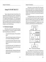
Before LAN switching, a typical network design looked like the network in Figure 4.14.
4309c04.fm Page 311 Thursday, October 23, 2003 4:51 PM
312
Chapter 4
Technology
FIGURE 4.14 Before switching
The design in Figure 4.14 was called a collapsed backbone because all hosts would need to
go to the corporate backbone to reach any network services—both LAN and mainframe.
Going back even further, before networks like the one shown in Figure 4.14 had physical
segmentation devices like routers and hubs, there was the mainframe network. This network
included the mainframe (IBM, Honeywell, Sperry, DEC, etc.), controllers, and dumb termi-
nals that connected into the controller. Any remote sites were connected to the mainframe
with bridges.
When the PC began its rise to stardom, the mainframe was connected to the Ethernet or to
a Token Ring LAN where the servers were installed. These servers were usually OS/2 or LAN
Manager because this was “pre-NT.” Each floor of a building ran either coax or twisted-pair
wiring to the corporate backbone and was then connected to a router. PCs ran an emulating
software program that allowed them to connect to the mainframe services, giving those PCs the
ability to access services from the mainframe and LAN simultaneously. Eventually the PC
became robust enough to allow application developers to port applications more effectively
than they ever could have before—this advance markedly reduced networking prices and
enabled businesses to grow at a much faster rate.
When Novell became more popular in the late 1980s and early 1990s, OS/2 and LAN
Manager servers were by and large replaced with Novell NetWare services. This made the
Ethernet network even more popular, because that’s what Novell 3.x servers used to commu-
nicate with client/server software.
So that’s the story of how the network in Figure 4.14 came into being. There was only one
problem with this—the corporate backbone grew and grew, and as it grew, network services
Corporate Remote Branch
Server Farm
Token Ring
Hubs
4309c04.fm Page 312 Thursday, October 23, 2003 4:51 PM
4.3 Compare and Contrast Key Characteristics of LAN Environments
313
became slower. A big reason for this was that, at the same time this huge burst in growth was
taking place. LAN services needed even faster service, and the network was becoming totally
saturated. Everyone was dumping the Macs and dumb terminals used for the mainframe service
in favor of those slick new PCs so that they could more easily connect to the corporate backbone
and network services.
All this was taking place before the Internet’s momentous popularity (Al Gore was still
inventing it?), so everyone in the company needed to access the corporate network’s services.
Why? Because without the Internet, all network services were internal—exclusive to the com-
pany network. The Internet created a screaming need to segment that one humongous and
plodding corporate network that was connected with sluggish old routers. At first, Cisco just
created faster routers (no doubt about that), but more segmentation was needed, especially on
the Ethernet LANs. The invention of FastEthernet was a very good and helpful thing too, but
it didn’t address that network segmentation need at all.
However, devices called bridges did, and they were first used in the network to break up col-
lision domains. But bridges were sorely limited by the number of ports and other network ser-
vices they could provide, and that’s when Layer 2 switches came to the rescue. These switches
saved the day by breaking up collision domains on every port, and switches could provide hun-
dreds of them! This early, switched LAN looked like the network pictured in Figure 4.15:
FIGURE 4.15 The first switched LAN
Switches
Corporate Remote Branch
Server Farm
Token Ring
Hubs
4309c04.fm Page 313 Thursday, October 23, 2003 4:51 PM
314
Chapter 4
Technology
Each hub was placed into a switch port, an innovation that vastly improved the network.
Now, instead of each building being crammed into the same collision domain, each hub became
its own separate collision domain. But there was a catch—switch ports were still very new, and
as a result, unbelievably expensive. Because of that, simply adding a switch into each floor of
the building just wasn’t going to happen—at least, not yet. Thanks to whomever you choose to
thank for these things, the price has dropped dramatically, so now, having every one of your
users plugged into a switch port is both good and feasible.
So there it is—if you’re going to create a network design and implement it, including
switching services is a must. A typical contemporary network design would look something
like Figure 4.16, which shows a complete switched network design and implementation.
“But I still see a router in there,” you say! Yes, it’s not a mirage—there is a router in there. But
its job has changed. Instead of performing physical segmentation, it now creates and handles log-
ical segmentation. Those logical segments are called VLANs.
FIGURE 4.16 The typical switched network design
Switching Services
Layer 2 switching is hardware based, which means it uses the MAC address from the host’s
NIC cards to filter the network. Unlike bridges that use software to create and manage a filter
table, switches use ASICs to build and maintain their filter tables. But it’s still okay to think
of a Layer 2 switch as a multiport bridge because their basic reason for being is the same: to
break up collision domains.
Layer 2 switches and bridges are faster than routers because they don’t take up time looking
at the Network layer header information. Instead, they look at the frame’s hardware addresses
before they decide to either forward the frame or drop it.
4309c04.fm Page 314 Thursday, October 23, 2003 4:51 PM
4.3 Compare and Contrast Key Characteristics of LAN Environments
315
Switches create private dedicated domains and don’t share bandwidth like a hub would. Fig-
ure 4.17 shows five hosts connected to a switch—all running 10Mbps half duplex to the server:
FIGURE 4.17 Switches create private domains
And unlike a hub, each host has 10Mbps dedicated communication to the server.
Layer 2 switching provides the following:
Hardware-based bridging (MAC)
Wire speed
Low latency reduced contention
Low cost
What makes Layer 2 switching so efficient is that no modification to the data packet takes
place. The device only reads the frame encapsulating the packet, which makes the switching
process considerably faster and less error-prone than routing processes are.
And if you use Layer 2 switching for both workgroup connectivity and network segmentation
(breaking up collision domains), you can create a flatter network design with more network seg-
ments than you can with traditional 10BaseT shared networks.
Plus, Layer 2 switching increases bandwidth for each user because, again, each connection
(interface) into the switch is its own collision domain. This feature makes it possible for you to
connect multiple devices to each interface.
Limitations of Layer 2 Switching
Since we commonly stick Layer 2 switching into the same category as bridged networks, we also
tend to think it has the same hang-ups and issues that bridged networks do. Keep in mind that
Server
10Mbps Half-duplex links
4309c04.fm Page 315 Thursday, October 23, 2003 4:51 PM
316
Chapter 4
Technology
bridges are good and helpful things if you design the network correctly, keeping their features
as well as their limitations in mind. And to design well with bridges, keep these two most
important considerations in mind:
You absolutely must break up the collision domains correctly.
The right way to create a functional bridged network is to make sure that its users spend
80 percent of their time on the local segment.
Bridged networks break up collision domains, but remember, that network is still one large
broadcast domain. Both Layer 2 switches and bridges don’t break up broadcast domains by
default—something that not only limits your network’s size and growth potential, but can also
reduce its overall performance.
Broadcasts and multicasts, along with the slow convergence time of spanning trees, can give
you some major grief as your network grows. These are the big reasons why Layer 2 switches
and bridges cannot completely replace routers (Layer 3 devices) in the internetwork.
Bridging versus LAN Switching
It’s true—Layer 2 switches really are pretty much just bridges that give us a bunch more ports,
but there are some important differences you should always keep in mind:
Bridges are software based, while switches are hardware based because they use ASIC chips
to help make filtering decisions.
A switch is basically a multiport bridge.
Bridges can only have one spanning-tree instance per bridge, while switches can have many.
Switches have a higher number of ports than most bridges.
Both bridges and switches forward Layer 2 broadcasts.
Bridges and switches learn MAC addresses by examining the source address of each frame
received.
Both bridges and switches make forwarding decisions based on Layer 2 addresses.
Three Switch Functions at Layer 2
There are three distinct functions of Layer 2 switching (you need to remember these!):
Address learning Layer 2 switches and bridges remember the source hardware address of each
frame received on an interface, and they enter this information into a MAC database called a
forward/filter table.
Forward/filter decisions When a frame is received on an interface, the switch looks at the
destination hardware address and finds the exit interface in the MAC database. The frame is
only forwarded out the specified destination port.
Loop avoidance If multiple connections between switches are created for redundancy purposes,
network loops can occur. STP is used to stop network loops while still permitting redundancy.
4309c04.fm Page 316 Thursday, October 23, 2003 4:51 PM
4.3 Compare and Contrast Key Characteristics of LAN Environments
317
LAN Switch Types
LAN switch types decide how a frame is handled when it’s received on a switch port. Latency—
the time it takes for a frame to be sent out an exit port once the switch receives the frame—
depends on the chosen switching mode. There are three switching modes: cut-through, Frag-
ment Free, and store-and-forward.
Figure 4.18 delimits the different points where the switching mode takes place in the frame.
FIGURE 4.18 Different switching modes within a frame
Okay—it’s time to talk about these three switching modes in more detail.
Cut-Through (Real Time)
With the cut-through switching method, the LAN switch copies only the destination address
(the first six bytes following the preamble) onto its onboard buffers. That done, it looks up the
hardware destination address in the MAC switching table, determines the outgoing interface,
and proceeds to forward the frame toward its destination.
A cut-through switch really helps reduce latency because it begins to forward the frame as soon
as it reads the destination address and determines the outgoing interface. And after it determines
the destination port, the following frames are immediately forwarded out through it.
With some switches, you get an extra super-cool feature: the flexibility to perform cut-through
switching on a per-port basis until a user-defined error threshold is reached. At the point that
threshold is attained, the ports automatically change over to store-and-forward mode, so they will
stop forwarding the errors. And, when the error rate on the port falls back below the threshold,
the port automatically changes back to cut-through mode.
FragmentFree (Modified Cut-Through)
FragmentFree is a modified form of cut-through switching in which the switch waits for the col-
lision window (64 bytes) to pass before forwarding. This is because if a packet has an error, it
almost always occurs within the first 64 bytes. So, in this mode, each frame will be checked into
the data field to make sure no fragmentation has occurred.
FragmentFree mode provides better error checking than the cut-through mode with practi-
cally no increase in latency. It’s the default switching method for the Catalyst 1900 switches.
Preamble SFD
Destination
hardware
addresses
Store-and-forward:
all errors filtered;
has highest latency
FragmentFree:
checks for
collisions
Cut-through:
no error checking
Source
hardware
addresses
Length DATA FCS
6 bytes 1 byte 6 bytes 6 bytes 2 bytes
Up to
1500 bytes 4 bytes
4309c04.fm Page 317 Thursday, October 23, 2003 4:51 PM
318
Chapter 4
Technology
Store-and-Forward
Store-and-forward switching is Cisco’s primary LAN switching method. When in store-and-forward,
the LAN switch copies the entire frame onto its onboard buffers and then computes the CRC. Because
it copies the entire frame, latency through the switch varies depending on the frame length.
The frame is discarded if it contains a CRC error—if it’s too short (less than 64 bytes including
the CRC), or if it’s too long (more than 1518 bytes including the CRC). If the frame doesn’t con-
tain any errors, the LAN switch looks up the destination hardware address in its forwarding or
switching table to find the correct outgoing interface. When it does, out goes the frame toward its
destination.
Wireless Networking
No book on this subject today would be complete without mentioning wireless networking.
That’s because two years ago, it just wasn’t all that common to find people using this tech-
nology. Remember, in 1996, a lot of people didn’t even have an e-mail address. Oh yeah—
sure, some did, but now everyone does, and the same thing is happening in the wireless world.
That’s because wireless networking is just way too convenient not to use. I’m betting that
some of you reading this probably have a wireless network at home. If not, you probably do
at work. I do! For this reason, I’m now going to go over the various types of wireless networks
as well as their speeds and distance limitations.
Narrowband Wireless LANs Narrowband radio does as its name suggests—it keeps the radio
signal frequency as narrow as possible while still being able to pass the information along. The
problem of interference is avoided by directing different users onto different channel frequencies.
The distance you get is decent, but the speeds available today just aren’t adequate enough for cor-
porate users. Plus, you’ve also got to have proprietary equipment to run it on, as well as buy a Fed-
eral Communications Commission (FCC) license to run the frequency at each site!
Personal Communication Services (PCS) Personal Communication Service (PCS) includes a
whole bunch of mobile, portable, and auxiliary communications services for individuals and
businesses. The FCC roughly defined PCS as mobile and fixed communications options for both
individuals and businesses that can be incorporated with various kinds of competing networks.
Narrowband or broadband PCS is what’s used today.
Narrowband PCS Again as the name implies, the narrowband PCS flavor requires a smaller
serving size of the spectrum than broadband PCS does. With licenses for narrowband PCS, you
get to access services like two-way paging and/or text-based messaging. Think about people
with PDAs, keyboard attachments, and so on getting and sending wireless e-mail—these sub-
scribers are able to do this via microwave signals. With narrowband PCS you can also access
cool services like wireless telemetry—the monitoring of mobile or stationary equipment remotely.
When the energy company remotely monitors your utility meters, commonly known as automatic
meter reading (AMR), they accomplish this using this technology.
Broadband PCS Broadband PCS is used for a many kinds of wireless services—both mobile
and fixed radio. The mobile broadband set includes both the voice and advanced two-way data
features usually available to us via small, mobile, multifunction devices like digital camera/cell
4309c04.fm Page 318 Thursday, October 23, 2003 4:51 PM
Exam Essentials
319
phones, and so on. In the industry, these services are commonly referred to as Mobile Telephone
Services and Mobile Data Services. Sources of these services include companies that rule huge
amounts of the broadband PCS spectrum like AT&T Wireless, Verizon, and Sprint PCS.
Satellite With satellite services, the speed you get is sweet—it’s up to around 1Mbps upload
and 2Mpbs download! But there’s an annoying delay when connecting, so it doesn’t work very
well when you’re dealing with bursty traffic. The good news is that speeds are increasing, but
even so, they just can’t compete with what you get via wireless LANs. The real upside to using
a satellite-based network is that its geographic coverage area can be huge.
Infrared Wireless LANs Here we have pretty much the opposite of satellite service. This tech-
nology works really well handling short, bursty traffic in the Personal Area Network (PAN)
sector. These speeds are increasing too, but the available range is still very short. It’s com-
monly used for laptop-to-laptop and laptop-to/PDA transfers. The speed range we usually
get is anywhere from 115Kbps to 4Mbps, but a new specification called Very Fast Infrared
(VFIR) says we’ll see speeds up to 16Mbps in the future—we’ll see!
Spread Spectrum Wireless LANs Your typical wireless LANs (WLANs) uses something called
spread spectrum. This is a wideband radio frequency technique that the military came up with
that’s both reliable, and secure (that’s debatable). The most popular WLAN in use today is
802.11b, which runs up to 11Mbps, but the new 802.11g specifications can bump that figure
up to around 22Mbps and more, depending on who made your equipment. Plus, the new 802.11a
lives in the 5Ghz range and can run bandwidth around 50Mbps—and it’s pledging over 100Mbps
in the near future! But the distance is still less than what you get with the 802.11b and 802.11g
2.4Ghz range models (which is about 300 feet or so). So basically, you usually find 802.11b/g
used indoors, and 802.11a in the shorter outdoor market where more bandwidth is needed.
Remember, the market is still young and who knows what the future holds for these up and
coming WLANs.
Exam Essentials
Know the four Ethernet frame types and the difference between them. Ethernet_II has a type
field, 802.3 has a length field, 802.2 has DSAPs and SSAPs, and SNAP has its own protocol field.
Understand how the cut-through LAN switch method works. When the switch is in this
mode, it waits only for the destination hardware address to be received before it looks up the
address in the MAC filter table.
Know the three LAN switch methods and their functions. The three LAN switch methods
are cut-through, FragmentFree (also known as modified cut-through) and store-and-forward.
Store-and-forward offers error checking; cut-through and FragmentFree offer lower latency.
Understand how the FragmentFree LAN switch method works. The FragmentFree LAN
switch method checks the first 64 bytes of a frame before forwarding it for fragmentation.
Understand how the store-and-forward LAN switch method works. Store-and-forward first
receives the complete data frame on the switch’s buffer, then a CRC is run, and then the switch
looks up the destination address in the MAC filter table.
4309c04.fm Page 319 Thursday, October 23, 2003 4:51 PM
320
Chapter 4
Technology
4.4 Evaluate the Characteristics of
Routing Protocols
All routing protocols have one task in common, that is, they are required to update the routing
tables on routers across the internetwork. Whether static or dynamic, distance vector or link
state, or even hybrid, routing protocols are required to make entries in the routing table. Let’s
take a deeper look at how the routing table is used once it is created by the individual routing
protocols.
See Section 1.3, “Select an appropriate routing protocol based on user require-
ments,” in this book, for more detailed information on different routing protocols.
The process of an IP packet being routed across an internetwork is fairly simple and doesn’t
change, regardless of the size of network you have. For an example, we’ll use Figure 4.19 to
describe step by step what happens when Host A wants to communicate with Host B on a dif-
ferent network.
FIGURE 4.19 IP routing example using two hosts and one router
In this example, a user on Host A pings Host B’s IP address. Routing doesn’t get simpler than
this, but it still involves a lot of steps. This entire process is dependent on the routing table being
filled by some routing protocol in a large internetwork. Let’s work through the routing steps:
1. Internet Control Message Protocol (ICMP) creates an echo request payload (which is just
the alphabet in the data field).
2. ICMP hands that payload to IP, which then creates a packet. At a minimum, this packet
contains an IP source address, IP destination address, and a protocol field with 01h. All that
tells the receiving host to whom it should hand the payload when the destination is reached—
in this example, ICMP.
3. Once the packet is created, IP works with the Address Resolution Protocol (ARP) to
determine whether the destination IP address is on the local network or a remote one.
4. Since ARP and IP determine this is a remote request, the packet needs to be sent to the
default gateway so that the packet can be routed to the remote network. The Registry in
Windows is parsed to find the configured default gateway.
Lab_A
Host_A
172.16.10.2
Host_B
172.16.20.2
E0
172.16.10.1
E1
172.16.20.1
4309c04.fm Page 320 Thursday, October 23, 2003 4:51 PM