CCNA: Fast Pass phần 7 pdf
Bạn đang xem bản rút gọn của tài liệu. Xem và tải ngay bản đầy đủ của tài liệu tại đây (526.53 KB, 39 trang )
218
Chapter 2
Implementation & Operation
Configuring Static Routes
To forward traffic across the ISDN link, you configure static routes in each of the routers. You
certainly can configure dynamic routing protocols to run on your ISDN link, but then the link
never drops. So the better choice would be static routes. Keep the following in mind when you
are creating static routes:
All participating routers must have static routes defining all routes of known networks.
Default routing can be used if the network is a stub network.
Here’s an example of static routing with ISDN:
RouterA(config)#ip route 172.16.50.0 255.255.255.0
172.16.60.2
RouterA(config)#ip route 172.16.60.2 255.255.255.255 bri0
What this does is tell the router how to get to network 172.16.50.0 through 172.16.60.2.
The second line tells the router how to get to 172.16.60.2.
Specifying Interesting Traffic
After setting the route tables in each router, you need to configure the router to determine what
brings up the ISDN line. An administrator using the dialer-list global configuration com-
mand defines interesting packets.
The command to turn on all IP traffic is shown in this output:
804A(config)#dialer-list 1 protocol ip permit
804A(config)#int bri0
804A(config-if)#dialer-group 1
The dialer-group command sets the access list on the BRI interface. Extended access lists
can be used with the dialer-list command to define interesting traffic to just certain appli-
cations. I’ll cover that in a minute.
If you use the dialer-list command, you must enter the dialer-group com-
mand on an interface before this will work!
Configuring the Dialer Information
There are five steps to configuring the dialer information:
1. Choose the interface.
2. Set the IP address.
3. Configure the encapsulation type.
4. Link interesting traffic to the interface.
5. Configure the number or numbers to dial.
4309c02.fm Page 218 Friday, October 24, 2003 2:55 PM
2.11 Implement Simple WAN Protocols
219
Here’s how to configure those five steps:
804A#config t
804A(config)#int bri0
804A(config-if)#ip address 172.16.60.1 255.255.255.0
804A(config-if)#no shut
804A(config-if)#encapsulation ppp
804A(config-if)#dialer-group 1
804A(config-if)#dialer string 8350661
Instead of the dialer string command, you can use a dialer map. It provides more security.
804A(config-if)#dialer map ip 172.16.60.2 name 804B
8350661
You can use the dialer map command with the dialer-group command and its associated
access list to initiate dialing. The dialer map command uses the IP address of the next hop
router, the hostname of the remote router for authentication, and then the number to dial to get
there.
The five basic Dialer Map steps that you must be aware of are:
1. Dialer
2. Map
3. Protocol
4. Next hop
5. Dial string
Remember, the dialer map command is used to associate an ISDN phone
number with the next hop router address.
Take a look at the configuration of an 804 router:
804B#sh run
Building configuration
Current configuration:
!
version 12.0
no service pad
service timestamps debug uptime
service timestamps log uptime
no service password-encryption
!
4309c02.fm Page 219 Friday, October 24, 2003 2:55 PM
220
Chapter 2
Implementation & Operation
hostname 804B
!
ip subnet-zero
!
isdn switch-type basic-ni
!
interface Ethernet0
ip address 172.16.50.10 255.255.255.0
no ip directed-broadcast
!
interface BRI0
ip address 172.16.60.2 255.255.255.0
no ip directed-broadcast
encapsulation ppp
dialer idle-timeout 300
dialer string 8358661
dialer load-threshold 2 either
dialer-group 1
isdn switch-type basic-ni
isdn spid1 0835866201 8358662
isdn spid2 0835866401 8358664
hold-queue 75 in
!
ip classless
ip route 172.16.30.0 255.255.255.0 172.16.60.1
ip route 172.16.60.1 255.255.255.255 BRI0
!
dialer-list 1 protocol ip permit
!
What can you determine by looking at this output? Well, first, the BRI interface is running the
PPP encapsulation, and it has a timeout value of 300 seconds. The load-threshold command
makes both BRI interfaces come up immediately—hey, I feel that if I am paying for both, I want
them both up all the time! The one thing you really want to notice is the dialer-group 1
command. That number must match the dialer-list number. The hold-queue 75 in command
tells the router that when it receives an interesting packet, it should queue up to 75 packets while
it’s waiting for the BRI to come up. If there are more than 75 packets queued before the link
comes up, the packets will be dropped.
4309c02.fm Page 220 Friday, October 24, 2003 2:55 PM
Exam Essentials
221
Optional Commands
There are two other commands that you should configure on your BRI interface: the dialer
load-threshold command and the dialer idle-timeout command.
The dialer load-threshold command tells the BRI interface when to bring up the second
B channel. The option is from 1 to 255, where 255 tells the BRI to bring up the second B channel
only when the first channel is 100 percent loaded. The second option for that command is in,
out, or either. This calculates the actual load on the interface either on outbound traffic, inbound
traffic, or combined. The default is outbound.
The dialer idle-timeout command specifies the number of seconds before a call is dis-
connected after the last interesting traffic is sent. The default is 120 seconds.
RouterA(config-if)#dialer load-threshold 125 either
RouterA(config-if)#dialer idle-timeout 180
The dialer load-threshold 125 tells the BRI interface to bring up the second B channel
if either the inbound or outbound traffic load is 50 percent. The dialer idle-timeout 180
changes the default disconnect time from 120 to 180 seconds.
DDR with Access Lists
You can use access lists to be more specific about what is, or is not interesting traffic. In the pre-
ceding example you just set the dialer list to allow any IP traffic to bring up the line. That’s great
if you’re testing, but it can defeat the purpose of why you use a DDR line in the first place. You
can use extended access lists to set the restriction, for instance, to only e-mail or Telnet.
Here’s how you define the dialer list to use an access list:
804A(config)#dialer-list 1 list 110
804A(config)#access-list 110 permit tcp any any eq smtp
804A(config)#access-list 110 permit tcp any any eq telnet
804A(config)#int bri0
804A(config-if)#dialer-group 1
I configured the dialer-list command to look at an access list. This doesn’t have to be
IP—it can be used with any protocol. Create your list, then apply it to the BRI interface with the
dialer-group command.
Exam Essentials
Know the commands for PPP encapsulation. You can use the encapsulation ppp command
on a serial interface to change from HDLC to PPP encapsulation. Also, you can further configure
authentication using the ppp authentication command.
4309c02.fm Page 221 Friday, October 24, 2003 2:55 PM
222
Chapter 2
Implementation & Operation
Know the commands for Frame Relay encapsulation. You can use the encapsulation frame-
relay command on a serial interface to change the encapsulation to Frame Relay. Additionally, you
will need to configure DLCI information, LMI and encapsulation types if they will differ from the
default, and potentially subinterfaces if you will have multiple PVCs per physical interface.
Understand the five basis dialer map steps for configuring DDR. The five steps are as
follows:
1. Dialer
2. Map
3. Protocol
4. Next hop
5. Dial string
4309c02.fm Page 222 Friday, October 24, 2003 2:55 PM
Review Questions
223
Review Questions
1. How is EIGRP implemented on a router?
A.
ip router eigrp as
B. router ip eigrp as
C. router eigrp process-id
D. router eigrp as
2. Which of the following commands will display a backup configuration?
A.
sh running-config
B. show startup-config
C. show version
D. show backup-config
3. Which command will show you whether a DTE or DCE cable is plugged into Serial 0?
A.
sh int s0
B. sh int serial 0
C. sho controllers s 0
D. sho controllers s0
4. Which command will copy the IOS to a backup host on your network?
A.
transfer IOS to 172.16.10.1
B. copy run start
C. copy tftp flash
D. copy start tftp
E. copy flash tftp
5. Which command will copy a router configuration stored on a TFTP host to the router’s NVRAM?
A.
transfer IOS to 172.16.10.1
B. copy run start
C. copy tftp startup
D. copy tftp run
E. copy flash tftp
4309c02.fm Page 223 Friday, October 24, 2003 2:55 PM
224
Chapter 2
Implementation & Operation
6. If you configure the following access list:
access-list 110 deny 10.1.1.128 0.0.0.63 eq smtp
access-list 110 deny any any eq 23
int ethernet 0
ip access-group 110 out
What will the result of this access list be?
A.
E-mail and Telnet will be allowed out E0.
B. E-mail and Telnet will be allowed in E0.
C. Everything but e-mail and Telnet will be allowed out E0.
D. No IP traffic will be allowed out E0.
7. Which of the following series of commands will restrict Telnet access to the router?
A.
Lab_A(config)#access-list 10 permit 172.16.1.1
Lab_A(config)#line con 0
Lab_A(config-line)#ip access-group 10 in
B. Lab_A(config)#access-list 10 permit 172.16.1.1
Lab_A(config)#line vty 0 4
Lab_A(config-line)#access-class 10 out
C. Lab_A(config)#access-list 10 permit 172.16.1.1
Lab_A(config)#line vty 0 4
Lab_A(config-line)#access-class 10 in
D. Lab_A(config)#access-list 10 permit 172.16.1.1
Lab_A(config)#line vty 0 4
Lab_A(config-line)#ip access-group 10 in
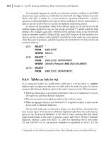
8. What is the default encapsulation type for Frame Relay in a Cisco router?
A.
HDLC
B. IEFT
C. Cisco
D. PPP
E. Ansi
F. Q933i
4309c02.fm Page 224 Friday, October 24, 2003 2:55 PM
Review Questions
225
9. Which of the following are the five basic steps to set up a dialer map command string?
A.
Dial-string, dialer, map, protocol, next-hop
B. Dialer, dial-string, map, protocol, next hop
C. Dialer, map, protocol, next hop, dial string
D. Dialer, map, next-hop, protocol, dial-string
10. Which of the following are valid PPP authentication methods? (Choose two options.)
A.
LCP
B. PAP
C. CHAP
D. MD5
4309c02.fm Page 225 Friday, October 24, 2003 2:55 PM
Answers to Review Questions
1. D. The command router eigrp followed by the autonomous system number is used to imple-
ment EIGRP. Process numbers are not used by EIGRP. All of the other command options have rad-
ically incorrect command syntax.
2. B. The show startup-config command will display the configuration that will be loaded the
next time the router is booted.
3. C. The show controllers serial 0 command will show you whether either a DTE or DCE
cable is connected to the interface.
4. E. To copy the IOS to a backup host, which is stored in flash memory by default, use the copy
flash tftp command.
5. C. To copy a configuration of a router stored on a TFTP host to a router’s NVRAM, use the
copy tftp startup-config command.
6. D. If you add an access list to an interface and you do not have at least one permit statement,
then you will effectively shut down the interface because of the implicit deny any at the end of
every list.
7. C. Telnet access to the router is restricted by using either a standard or extended IP access list to
the VTY lines on the router. The command access-class is used to apply the access list to the
VTY lines.
8. C. If you just type from interface configuration mode, encapsulation frame-relay, the
encapsulation type will be Cisco.
9. C. The five basic Dialer Map steps that you must be aware of are:
1.
Dialer
2. Map
3. Protocol
4. Next hop
5. Dial string
10. B, C. PAP and CHAP are valid authentication methods available to PPP authentication.
4309c02.fm Page 226 Friday, October 24, 2003 2:55 PM
Chapter
3
Troubleshooting
CISCO CCNA EXAM OBJECTIVES COVERED
IN THIS CHAPTER:
3.1 Utilize the OSI model as a guide for systematic network
troubleshooting
3.2 Perform LAN and VLAN troubleshooting
3.3 Troubleshoot routing protocols
3.4 Troubleshoot IP addressing and host configuration
3.5 Troubleshoot a device as part of a working network
3.6 Troubleshoot an access list
3.7 Perform simple WAN troubleshooting
4309c03.fm Page 227 Thursday, October 23, 2003 4:48 PM
When networks first came into being, computers could typically
communicate only with computers from the same manufacturer.
For example, companies ran either a complete DECnet solution
or an IBM solution—not both together. In the late 1970s, the International Organization for
Standardization (ISO) created the Open Systems Interconnection (OSI) reference model to
break this barrier.
3.1 Utilize the OSI Model as a Guide for
Systematic Network Troubleshooting
When networks first came into being, computers could typically communicate only with com-
puters from the same manufacturer. For example, companies ran either a complete DECnet
solution or an IBM solution—not both together. In the late 1970s, the International Organi-
zation for Standardization (ISO) created the Open Systems Interconnection (OSI) reference
model to break this barrier.
The OSI model was meant to help vendors create interoperable network devices and soft-
ware in the form of protocols so that different vendor networks could work with each other.
Like world peace, it’ll probably never happen completely, but it’s still a great goal.
The OSI model is the primary architectural model for networks. It describes how data and network
information are communicated from an application on one computer, through the network media, to
an application on another computer. The OSI reference model breaks this approach into layers.
In this section, we will look at the OSI layered approach and it’s practical implications on
real-world networks—the five steps of data encapsulation. Understanding the five steps of data
encapsulation is crucial in real-world troubleshooting.
The Layered Approach
A
reference model
is a conceptual blueprint of how communications should take place. It
addresses all the processes required for effective communication and divides these processes
into logical groupings called
layers
. When a communication system is designed in this manner,
it’s known as
layered architecture
.
Think of it like this: you and some friends want to start a company. One of the first things
you’d do is sit down and think through what tasks must be done, who will do them, what order
4309c03.fm Page 228 Thursday, October 23, 2003 4:48 PM
3.1 Utilize the OSI Model as a Guide for Systematic Network Troubleshooting
229
they will be done in, and how they relate to each other. Ultimately, you might group these tasks
into departments. Let’s say you decide to have an order-taking department, an inventory depart-
ment, and a shipping department. Each of your departments has its own unique tasks, keeping its
staff members busy and requiring them to focus on only their own duties.
In this scenario, I’m using departments as a metaphor for the layers in a communication
system. For things to run smoothly, the staff of each department has to trust and rely heavily upon
the others to do their jobs and competently handle their unique responsibilities. In your planning
sessions, you should probably take notes, recording the entire process to facilitate later discussions
about standards of operation that will serve as your business blueprint, or reference model.
Okay, once your business is launched, your department heads, armed with the part of the blue-
print that relates to their department, will need to develop practical methods to implement their
assigned tasks. These practical methods, or
protocols
, will need to be compiled into a standard
operating procedures manual and followed closely. Each of the various procedures in your manual
will have been included for different reasons and have varying degrees of importance and implemen-
tation. If you form a partnership or acquire another company, it will be imperative for its business
protocols—its business blueprint—to match yours (or at least be compatible with it).
The seven layers of the OSI model are discussed in detail in Chapter 4,
“Technology.”
Similarly, software developers can use a reference model to understand computer communi-
cation processes and see what types of functions need to be accomplished on any one layer. If
they are developing a protocol for a certain layer, all they need to concern themselves with is the
specific layer’s functions, not those of any other layer. Another layer and protocol will handle
the other functions. The technical term for this idea is
binding
. The communication processes
that are related to each other are bound, or grouped together, at a particular layer.
Advantages of Reference Models
The OSI is hierarchical, and the benefits and advantages of this type of model can apply to
any layered model. The primary purpose of all models, especially the OSI model, is to allow
different vendors’ networks to interoperate.
Advantages of using the OSI layered model include, but are not limited to, the following:
Allows multiple-vendor development through standardization of network components
Allows various types of network hardware and software to communicate
Prevents changes in one layer from affecting other layers, so it does not hamper development
The implications of layered models have significant impact on troubleshooting scenarios. Since
changes in one layer do not affect other layers, if you can successfully identify which layer of a
layered model is causing the problem, you can safely rule out the components of other layers
(assuming you only have one problem, which is not always the case!). For example, if you know
4309c03.fm Page 229 Thursday, October 23, 2003 4:48 PM
230
Chapter 3
Troubleshooting
you have a TCP tuning problem (Layer 4), you can rule out Ethernet configuration (Layer 2)
and IP addressing (Layer 3). This allows you to focus on the real problem and not waste time
addressing layers that are already working and are not contributing to the problem. Layered
models contribute directly to problem isolation in troubleshooting scenarios.
Next I will explain how the layered OSI model applies in network communications. This
process is called
data encapsulation
.
Data Encapsulation
When a host transmits data across a network to another device, the data goes through encap-
sulation: it is wrapped with protocol information at each layer of the OSI model. Each layer
communicates only with its peer layer on the receiving device.
To communicate and exchange information, each layer uses Protocol Data Units (PDUs). These
hold the control information attached to the data at each layer of the model. They are usually
attached to the header in front of the data field, but they can also be in the trailer, or end, of it.
Each PDU is attached to the data by encapsulating it at each layer of the OSI model, and each
has a specific name depending on the information provided in each header. This PDU informa-
tion is only read by the peer layer on the receiving device. After it’s read, it’s stripped off, and
the data is then handed to the next layer up.
Figure 3.1 shows the PDUs and how they attach control information to each layer. This fig-
ure demonstrates how the upper-layer user data is converted for transmission on the network.
The data stream is then handed down to the Transport layer, which sets up a virtual circuit to
the receiving device by sending over a synch packet. The data stream is then broken up into
smaller pieces, and a Transport layer header (a PDU) is created and attached to the header of
the data field; now the piece of data is called a
segment
. Each segment is sequenced so the data
stream can be put back together on the receiving side exactly as it was transmitted.
FIGURE 3.1
Data encapsulation
Application
Presentation
Session
Transport
Network
Data Link
Physical
Segment
PDU
Packet
Frame
Bits
Upper layer dataTCP header
DataIP header
DataLLC header
DataMAC header
0101110101001000010
Upper layer data
FCS
FCS
4309c03.fm Page 230 Thursday, October 23, 2003 4:48 PM
3.1 Utilize the OSI Model as a Guide for Systematic Network Troubleshooting
231
Each segment is then handed to the Network layer for network addressing and routing through
the internetwork. Logical addressing (for example, Internet Protocol [IP]) is used to get each seg-
ment to the correct network. The Network layer protocol adds a control header to the segment
handed down from the Transport layer, and what you have at this point is called a
packet
or
dat-
agram
. Remember that the Transport and Network layers work together to rebuild a data stream
on a receiving host, but it’s not part of their work to place their PDUs on a local network segment—
which is the only way to get the information to a router or host.
It’s the Data Link layer that’s responsible for taking packets from the Network layer and
placing them on the network medium (cable or wireless). The Data Link layer encapsulates each
packet in a frame, and the frame’s header carries the hardware address of the source and des-
tination hosts. If the destination device is on a remote network, then the frame is sent to a router
to be routed through an internetwork. Once it gets to the destination network, a new frame is
used to get the packet to the destination host.
To put this frame on the network, you must first put it into a digital signal. Since a frame is
really a logical group of 1s and 0s, the Physical layer is responsible for encoding these digits into
a digital signal, which is read by devices on the same local network. The receiving devices syn-
chronize on the digital signal and extract (decode) the ones and zeros from the digital signal. At
this point, the devices build the frames, run a cyclic redundancy check (CRC), and then check
their answer against the answer in the frame’s frame check sequence (FCS) field. If it matches,
the packet is pulled from the frame, and what’s left of the frame is discarded. This process is
called
de-encapsulation
. The packet is handed to the Network layer, where the address is checked.
If the address matches, the segment is pulled from the packet, and what’s left of the packet is dis-
carded. The segment is processed at the Transport layer, which rebuilds the data stream and
acknowledges to the transmitting station that it received each piece. It then happily hands the data
stream to the upper-layer application.
To summarize, at a transmitting device, the data encapsulation method works like this:
1.
User information is converted to data for transmission on the network.
2.
Data is converted to segments and a reliable connection is set up between the transmitting
and receiving hosts.
3.
Segments are converted to packets or datagrams, and a logical address is placed in the
header so that each packet can be routed through an internetwork.
4.
Packets or datagrams are converted to frames for transmission on the local network. Hard-
ware (Ethernet) addresses are used to uniquely identify hosts on a local network segment.
5.
Frames are converted to bits, and a digital encoding and clocking scheme is used.
The receiving device will follow these steps in reverse order to de-encapsulate the user information.
In real-world troubleshooting scenarios, understanding these steps of data encapsulation is
probably the most important skill that derives from the OSI layered model. In many problem sit-
uations, you end up looking at packet traces or
sniffer traces
as they are often called. Sniffer is
actually one of many tools called protocol analyzers that can capture frames from a wire and dis-
play them. These tools are able to analyze the headers on the PDUs, and display the frame, packet,
segment, and often data headers. However, they don’t always
explain
the headers, and thus a clear
understanding of data encapsulation is required to understand the information they present.
4309c03.fm Page 231 Thursday, October 23, 2003 4:48 PM
232
Chapter 3
Troubleshooting
Exam Essentials
Remember that the OSI model is a layered approach.
Functions are divided into layers, and
the layers are bound together. This allows layers to operate transparently to each other; that is,
changes in one layer should not impact other layers.
Know the steps of data encapsulation.
User information is encapsulated to data, data to
segments, segments to packets or datagrams, packets or datagrams to frames, and frames
to bits.
3.2 Perform LAN and VLAN
Troubleshooting
When troubleshooting a VLAN environment you will use a variety of techniques. Remember
that each VLAN is a separate subnet, and that all communications between VLANS must be
routed. Therefore, troubleshooting communications between VLANS is the same as trouble-
shooting any other routing issue between subnets (we’ll cover troubleshooting IP addressing and
routing shortly). Validation of trunking protocols (ISL, 802.1q) and Spanning Tree Protocol
(STP) configurations is also required (these are covered in Chapters 2 and 4). Initially, you will
probably end up looking at which VLANs are configured on a switch, and which ports are in
those VLANs. Mapping which ports are in which VLANs will almost always be the starting point
for troubleshooting LAN/VLAN issues.
On a Catalyst 1900, you can verify VLAN configuration with the
show vlan
command
(
sh vlan
for short):
1900#
sh vlan
VLAN Name Status Ports
1 default Enabled 1-12, AUI, A, B
2 sales Enabled
3 marketing Enabled
4 mis Enabled
1002 fddi-default Suspended
1003 token-ring-defau Suspended
1004 fddinet-default Suspended
1005 trnet-default Suspended
[output cut]
4309c03.fm Page 232 Thursday, October 23, 2003 4:48 PM
3.2 Perform LAN and VLAN Troubleshooting
233
On a Catalyst 2950, you must examine the contents of the VLAN database. To see the
VLAN database, use the
show vlan
command or the
show vlan brief
command:
Switch#
sh vlan brief
VLAN Name Status Ports
1 default active Fa0/1, Fa0/2, Fa0/3, Fa0/4
Fa0/7, Fa0/8, Fa0/9, Fa0/10
Fa0/11, Fa0/12
2 Marketing active
3 Accounting active
4 Shipping active
21 VLAN0021 active
22 VLAN0022 active
51 VLAN0051 active
52 VLAN0052 active
1002 fddi-default active
1003 token-ring-default active
1004 fddinet-default active
1005 trnet-default active
Switch#
Remember that VLAN Trunk Protocol (VTP) can dynamically make changes to the VLAN
configuration on a switch if it is enabled. You can check the status of VTP with the
show vtp
command:
SwitchA#sh vtp ?
counters VTP statistics
status VTP domain status
SwitchA#sh vtp status
VTP Version : 2
Configuration Revision : 1
Maximum VLANs supported locally : 64
Number of existing VLANs : 7
VTP Operating Mode : Server
VTP Domain Name : routersim
VTP Pruning Mode : Disabled
VTP V2 Mode : Disabled
VTP Traps Generation : Disabled
4309c03.fm Page 233 Thursday, October 23, 2003 4:48 PM
234
Chapter 3
Troubleshooting
MD5 digest : 0x4C 0x60 0xA6 0x5D 0xD7 0x41 0x8C 0x37
Configuration last modified by 172.16.10.1 at 3-1-94 06:40:09
Local updater ID is 172.16.10.1 on interface Vl1 (lowest numbered VLAN interface
found)
Exam Essentials
Know the commands to find which VLANs are configured on a switch
Use the
show
vlan
command on the Catalyst 1900 to see the configured VLANs, or use the same command on the
Catalyst 2950 to examine the contents of the VLAN database.
Know the implications of VTP
Changes to VLAN configurations can propagate between
switches; your VTP mode must be transparent if you do not want your switches to participate
in VTP.
3.3 Troubleshoot Routing Protocols
Troubleshooting routing protocols and issues is, in many ways, one of the most fundamental
skills you are expected to develop as a CCNA. After all, if routers don’t route, what else really
matters? In this section, we will look at a few general commands to troubleshoot routing
protocols, and then take a closer look at each of the four routing protocols covered by the
CCNA exam.
It’s important to verify your configurations once you’ve completed them, or at least once
you
think
you’ve completed them. The same commands are used to troubleshoot routing pro-
tocols that are used to verify them. These commands tell you if the router is, well, routing. The
following list includes the commands you can use to verify the routed and routing protocols
configured on your Cisco routers.
The show ip route command
This command is one of the most frequently used commands;
it displays the current contents of the routing table.
Lab_A#sh ip route
[output cut]
Gateway of last resort is not set
D 192.168.30.0/24 [90/2172416] via 192.168.20.2,00:04:36, Serial0/0
C 192.168.10.0/24 is directly connected, FastEthernet0/0
D 192.168.40.0/24 [90/2681856] via 192.168.20.2,00:04:36, Serial0/0
C 192.168.20.0/24 is directly connected, Serial0/0
D 192.168.50.0/24 [90/2707456] via 192.168.20.2,00:04:35, Serial0/0
Lab_A#
4309c03.fm Page 234 Thursday, October 23, 2003 4:48 PM
3.3 Troubleshoot Routing Protocols
235
The show protocols command This command is useful because it displays all the routed
protocols and the interfaces upon which the protocol is enabled.
Lab_B#sh protocol
Global values:
Internet Protocol routing is enabled
FastEthernet0 is up, line protocol is up
Internet address is 192.168.30.1/24
Serial0/0 is up, line protocol is up
Internet address is 192.168.20.2/24
Serial0/1 is up, line protocol is up
Internet address is 192.168.40.1/24
Lab_B#
This output shows the IP address of the FastEthernet 0/0, Serial 0/0, and Serial 0/1 interfaces of
the Lab_B router. If IPX or AppleTalk were configured on the router, those network addresses
would’ve appeared as well.
The show ip protocol command The show ip protocol command shows you the routing
protocols that are configured on your router. If you look at the following output, you can see
that both Routing Information Protocol (RIP) and Interior Gateway Routing Protocol (IGRP)
are running on the router, but that only IGRP appears in the routing table because of its lower
administrative distance (AD).
The show ip protocols command also displays the timers used in the routing protocol. Now take
a look in the next section of output; you can see that RIP is sending updates every 30 seconds—
the default. Further down, you’ll notice that RIP is routing for all directly connected networks,
and the two neighbors it found are 192.168.40.2 and 192.168.20.1.
Lab_B#sh ip protocols
Routing Protocol is "rip"
Sending updates every 30 seconds, next due in 6 seconds
Invalid after 180 seconds, hold down 180, flushed after
240
Outgoing update filter list for all interfaces is
Incoming update filter list for all interfaces is
Redistributing: rip
Default version control: send version 1, receive any
version
Interface Send Recv Key-chain
FastEthernet0 1 1 2
Serial0/0 1 1 2
Serial0/1 1 1 2
4309c03.fm Page 235 Thursday, October 23, 2003 4:48 PM
236
Chapter 3
Troubleshooting
Routing for Networks:
192.168.10.0
192.168.20.0
192.168.30.0
Routing Information Sources:
Gateway Distance Last Update
192.168.40.2 120 00:00:21
192.168.20.1 120 00:00:23
Distance: (default is 120)
Routing Protocol is "igrp 10"
Sending updates every 90 seconds, next due in 42 seconds
Invalid after 270 seconds, hold down 280, flushed after
630
Outgoing update filter list for all interfaces is
Incoming update filter list for all interfaces is
Default networks flagged in outgoing updates
Default networks accepted from incoming updates
IGRP metric weight K1=1, K2=0, K3=1, K4=0, K5=0
IGRP maximum hopcount 100
IGRP maximum metric variance 1
Redistributing: eigrp 10, igrp 10
Routing for Networks:
192.168.10.0
192.168.20.0
192.168.30.0
Routing Information Sources:
Gateway Distance Last Update
192.168.40.2 100 00:00:47
192.168.20.1 100 00:01:18
Distance: (default is 100)
The information included in the show ip protocols command includes the autonomous
system (AS), routing timers, networks being advertised, gateways, and AD (100).
You can use these commands on all IP routing protocols; basically, regardless of which routing
protocol you are running, these can and should be used. What’s next? Now I’ll talk about some
specific commands you can use with individual routing protocols to further troubleshoot their
operation. These commands, including their associated debug commands, are specific to the
routing protocols mentioned. I’ll begin with Routing Information Protocol (RIP) and then look
at Interior Gateway Routing Protocol (IGRP), Enhanced Interior Gateway Routing Protocol
(EIGRP), and Open Shortest Path First (OSPF).
4309c03.fm Page 236 Thursday, October 23, 2003 4:48 PM
3.3 Troubleshoot Routing Protocols
237
Troubleshooting RIP
Occasionally, the commands we just discussed will not be sufficient to figure out what is
happening. When you need to look more thoroughly at what RIP is doing, you can use
debug commands to monitor RIP events on the router.
The debug ip rip command sends information about routing updates as they are sent and
received by the router to the console session. If you are telnetted into the router, you’ll need to use
the terminal monitor command to be able to receive the output from the debug commands.
In the following output, you can see that RIP is both sent and received on Serial 0/0 and Serial
0/1 interfaces. This is a sweet troubleshooting tool! The metric is the hop count.
Lab_B#debug ip rip
RIP protocol debugging is on
Lab_B#
07:12:56: RIP: received v1 update from 192.168.40.2 on
Serial0/1
07:12:56: 192.168.50.0 in 1 hops
07:12:56: RIP: received v1 update from 192.168.20.1 on
Serial0/0
07:12:56: 192.168.10.0 in 1 hops
In the preceding debug output, notice the route updates received on the Lab_B serial 0/0 and
serial 0/1 interfaces. These are from routers Lab_A and Lab_C, respectively. What’s important
to nail here is that split-horizon rules stop the Lab_A and Lab_C routers from advertising back
routes that they learned from Lab_B. This means that only network 192.168.50.0 is being
advertised from Lab_C, and 192.168.10.0 is being advertised to Lab_B from Lab_A. Here is
another debug.
07:12:58: RIP: sending v1 update to 255.255.255.255 via
FastEthernet0/0 (192.168.30.1)
07:12:58: subnet 192.168.50.0, metric 1
07:12:58: subnet 192.168.40.0, metric 1
07:12:58: subnet 192.168.20.0, metric 1
07:12:58: subnet 192.168.10.0, metric 1
07:12:58: RIP: sending v1 update to 255.255.255.255 via
Serial0/0 (172.16.20.2)
07:12:58: subnet 192.168,50.0, metric 1
07:12:58: subnet 192.168.40.0, metric 1
07:12:58: subnet 192.168.30.0, metric 1
07:12:58: RIP: sending v1 update to 255.255.255.255 via
Serial0/1 (172.16.40.1)
07:12:58: subnet 192.168.30.0, metric 1
07:12:58: subnet 192.168.20.0, metric 1
07:12:58: subnet 192.168.10.0, metric 1
4309c03.fm Page 237 Thursday, October 23, 2003 4:48 PM
238
Chapter 3
Troubleshooting
In the preceding output, split-horizon rules only allow networks 192.168.30.0, 40, and 50
to be advertised to Lab_A. Router Lab_B will not advertise the 192.168.10.0 network back to
the Lab_A router, nor 192.168.50.0 back to Lab_C. Let’s close down the debugger.
If the metric of a route shows 16, this is a route poison, and the
route being advertised is unreachable.
Lab_B#undebug all
All possible debugging has been turned off
Lab_B#
To turn off debugging, use the undebug all or the no debug all command. You can also
use the un all shortcut command.
Troubleshooting IGRP
With the debug ip igrp command, there are two options, events and transactions, as
shown in this output:
Lab_B#debug ip igrp ?
events IGRP protocol events
transactions IGRP protocol transactions
The difference between these commands is explained in the following sections.
The Debug IP IGRP Events Command
The debug ip igrp events command is a summary of the IGRP routing information that is
running on the network. The following router output shows the source and destination of each
update as well as the number of routers in each update. Information about individual routes
isn’t something you’ll get with this command.
Lab_B#debug ip igrp events
IGRP event debugging is on
07:13:50: IGRP: received request from 192.168.40.2 on
Serial0/1
07:13:50: IGRP: sending update to 192.168.40.2 via Serial1
(192.168.40.1)
07:13:51: IGRP: Update contains 3 interior, 0 system, and
0 exterior routes.
4309c03.fm Page 238 Thursday, October 23, 2003 4:48 PM
3.3 Troubleshoot Routing Protocols
239
07:13:51: IGRP: Total routes in update: 3
07:13:51: IGRP: received update from 192.168.40.2 on
Serial0/1
07:13:51: IGRP: Update contains 1 interior, 0 system, and
0 exterior routes.
07:13:51: IGRP: Total routes in update: 1
You can turn the command off with the undebug or undebug all command.
Lab_B#un all
All possible debugging has been turned off
The Debug IP IGRP Transactions Command
The debug ip igrp transactions command shows message requests from neighbor routers
asking for an update and the broadcasts sent from your router toward that neighbor
router.
In the following output, a request was received from a neighbor router on network
192.168.40.2 to Serial 0/1 of Router Lab_B, which responded with an update packet:
Lab_B#debug ip igrp transactions
IGRP protocol debugging is on
07:14:05: IGRP: received request from 192.168.40.2 on
Serial1
07:14:05: IGRP: sending update to 192.168.40.2 via Serial1
(172.16.40.1)
07:14:05: subnet 192.168.30.0, metric=1100
07:14:05: subnet 8192.16.20.0, metric=158250
07:14:05: subnet 192.168.10.0, metric=158350
07:14:06: IGRP: received update from 192.168.40.2 on
Serial1
07:14:06: subnet 192.168.50.0, metric 8576 (neighbor
1100)
You can turn off the command with the undebug all command (un all for short).
Lab_B#un all
All possible debugging has been turned off
4309c03.fm Page 239 Thursday, October 23, 2003 4:48 PM
240
Chapter 3
Troubleshooting
Troubleshooting EIGRP
You can use several commands on a router to help you troubleshoot and verify the EIGRP con-
figuration. Table 3.1 contains all of the commands that are used in conjunction with verifying
EIGRP operation, and it offers a brief description of what each command does.
Since we have already looked at the show ip route command, let’s take a look at the other
two show commands commonly used to troubleshoot EIGRP. First, familiarize yourself with
show ip eigrp neighbor:
Lab_C#show ip eigrp neighbor
H Address Interface Hold Uptime SRTT RTO Q Seq Type
(sec) (ms) Cnt Num
0 192.168.40.1 Se0 12 00:13:24 26 200 0 7
Let me break this down for you:
H indicates the order in which the neighbors were discovered.
The Hold time indicates how long this router will wait for a Hello packet to arrive from a
specific neighbor.
The Uptime indicates how long the neighborship has been established.
The SRTT field is the smooth round-trip timer, which indicates the time a round trip takes
from this router to its neighbor and back. You use this value to determine how long to wait
after a multicast for a reply from this neighbor. If a reply isn’t received in time, the router
switches to using unicasts in an attempt to complete the communication. The time between
multicast attempts is specified by…
The RTO field, which stands for Retransmission Time Out, is itself based upon the SRTT values.
The Q value indicates whether there are any outstanding messages in the queue—consistently
large values would indicate a problem.
The Seq field indicates the sequence number of the last update from that neighbor—which is used
to maintain synchronization and avoid duplicate or out-of-sequence processing of messages.
TABLE 3.1 EIGRP Troubleshooting Commands
Command Description/Function
show ip route Shows the entire routing table
show ip eigrp route Shows only EIGRP entries in the routing table
show ip eigrp neighbor Shows all EIGRP neighbors
show ip egrp topology Shows entries in the EIGRP topology table
4309c03.fm Page 240 Thursday, October 23, 2003 4:48 PM
3.3 Troubleshoot Routing Protocols
241
Okay—it’s all good. Now let’s see what’s in the show ip eigrp topology command:
Lab_C#show ip eigrp topology
Codes: P - Passive, A - Active, U - Update, Q - Query, R - Reply,
r - reply Status, s - sia Status
P 192.168.40.0/24, 1 successors, FD is 2169856
via Connected, Serial0
P 192.168.50.0/24, 1 successors, FD is 281600
via Connected, Ethernet0
P 192.168.10.0/24, 1 successors, FD is 2707456
via 192.168.40.1 (2707456/2195456), Serial0/0
P 192.168.30.0/24, 1 successors, FD is 2172416
via 192.168.40.1 (2172416/28160), Serial0/0
P 192.168.20.0/24, 1 successors, FD is 2681856
via 192.168.40.1 (2681856/2169856), Serial0/0
Lab_C#
Notice that every route is preceded by a P. This means that the route is in the passive state,
which is good. Routes in the active state indicate that the router has lost its path to this network
and is searching for a replacement. Each entry also indicates the feasible distance, or FD, to each
remote network plus the next-hop neighbor through which packets will travel to this destina-
tion. Each entry also has two numbers in parentheses—for example, (2681856/2169856). The
first number indicates the feasible distance, and the second indicates the advertised distance to
a remote network.
Troubleshooting OSPF
There are several ways to verify and troubleshoot proper OSPF configuration and operation; I’ll
show you the OSPF show commands you need to know about to do this. They include
show ip ospf
show ip ospf database
show ip ospf interface
show ip ospf neighbor
In this section, not only will we look at these commands, but we’ll also take another look at
the show ip protocols command to see how it stacks up in OSPF.
The show ip ospf command
You can use the show ip ospf command to display OSPF information for one or all OSPF
processes running on the router. Information contained therein includes the Router ID,
4309c03.fm Page 241 Thursday, October 23, 2003 4:48 PM
242
Chapter 3
Troubleshooting
area information, SPF (Shortest Path First) statistics, and Link State Advertisement (LSA)
timer information. Let’s check out the output:
Lab_A#sho ip ospf
Routing Process "ospf 132" with ID 192.168.20.1
Supports only single TOS(TOS0) routes
Supports opaque LSA
SPF schedule delay 5 secs, Hold time between two SPFs 10 secs
Minimum LSA interval 5 secs. Minimum LSA arrival 1 secs
Number of external LSA 0. Checksum Sum 0x000000
Number of opaque AS LSA 0. Checksum Sum 0x000000
Number of DCbitless external and opaque AS LSA 0
Number of DoNotAge external and opaque AS LSA 0
Number of areas in this router is 1. 1 normal 0 stub 0 nssa
External flood list length 0
Area BACKBONE(0)
Number of interfaces in this area is 2
Area has no authentication
SPF algorithm executed 5 times
Area ranges are
Number of LSA 3. Checksum Sum 0x020E9A
Number of opaque link LSA 0. Checksum Sum 0x000000
Number of DCbitless LSA 0
Number of indication LSA 0
Number of DoNotAge LSA 0
Flood list length 0
Notice the RID of 192.168.20.1, which is the highest IP address in the router. Now let’s take
a look at the OSPF database.
The show ip ospf database Command
The information displayed by the show ip ospf database command indicates the number of
links and the neighboring router’s ID. The output is broken down by area. Here’s a sample output:
Lab_A#sh ip ospf database
OSPF Router with ID (192.168.20.1) (Process ID 132)
Router Link States (Area 0)
4309c03.fm Page 242 Thursday, October 23, 2003 4:48 PM