CCNA: Fast Pass phần 6 docx
Bạn đang xem bản rút gọn của tài liệu. Xem và tải ngay bản đầy đủ của tài liệu tại đây (508.15 KB, 39 trang )
2.8 Perform an Initial Configuration on a Router
179
You can view the description of an interface either with the show running-config command
or the show interface command.
Atlanta#sh run
[cut]
interface Ethernet0
description Sales Lan
ip address 172.16.10.30 255.255.255.0
no ip directed-broadcast
!
interface Serial0
description Wan to Miami circuit:6fdda4321
no ip address
no ip directed-broadcast
no ip mroute-cache
Atlanta#sh int e0
Ethernet0 is up, line protocol is up
Hardware is Lance, address is 0010.7be8.25db (bia
0010.7be8.25db)
Description: Sales Lan
[output cut]
Atlanta#sh int s0
Serial0 is up, line protocol is up
Hardware is HD64570
Description: Wan to Miami circuit:6fdda4321
[output cut]
Atlanta#
Viewing and Saving Configurations
If you run through setup mode, you’ll be asked if you want to use the configuration you just created.
If you say Yes, it will copy the configuration running in DRAM (known as the running-config) into
NVRAM and name the file startup-config.
You can manually save the file from DRAM to NVRAM by using the copy running-
config startup-config command. You can use the shortcut copy run start also:
Atlanta#copy run start
Destination filename [startup-config]?[Enter]
Warning: Attempting to overwrite an NVRAM configuration
previously written by a different version of the system
image.
4309c02.fm Page 179 Friday, October 24, 2003 2:55 PM
180
Chapter 2
Implementation & Operation
Overwrite the previous NVRAM configuration?[confirm]
[Enter]
Building configuration
Notice that the message you received here tells you you’re trying to write over the older
startup-config. The IOS had been just upgraded to version 12.2, and the last time the file was
saved, 11.3 was running. When you see a question with an answer in [], it means that if you
just press Enter, you’re choosing the default answer.
Also, when the command asked for the destination filename, the default answer was
startup-config. The “feature” aspect of this command output is that you can’t even type
anything else in or you’ll get an error!
Atlanta#copy run start
Destination filename [startup-config]?todd
%Error opening nvram:todd (No such file or directory)
Atlanta#
Okay, you’re right—it’s weird! Why on earth do they even ask if you can’t change it at all?
Well, since this “feature” was first introduced with the release of the 12.x IOS, we’re all pretty
sure it will turn out to be relevant and important some time in the future.
Anyway, you can view the files by typing show running-config or show startup-config
from privileged mode. The sh run command, which is the shortcut for show running-config,
tells you that you are viewing the current configuration:
Atlanta#sh run
Building configuration
Current configuration:
!
version 12.0
service timestamps debug uptime
service timestamps log uptime
no service password-encryption
!
hostname Atlanta
ip subnet-zero
frame-relay switching
!
[output cut]
4309c02.fm Page 180 Friday, October 24, 2003 2:55 PM
2.8 Perform an Initial Configuration on a Router
181
The sh start command—the shortcut for the show startup-config command—shows
you the configuration that will be used the next time the router is reloaded. It also tells you how
much NVRAM is being used to store the startup-config file:
Atlanta#sh start
Using 4850 out of 32762 bytes
!
version 12.0
service timestamps debug uptime
service timestamps log uptime
no service password-encryption
!
hostname Atlanta
!
!
ip subnet-zero
frame-relay switching
!
[output cut]
You can delete the startup-config file by using the erase startup-config command, after
which you’ll receive an error if you ever try to view the startup-config file.
Atlanta#erase startup-config
Erasing the nvram filesystem will remove all files!
Continue? [confirm]
[OK]
Erase of nvram: complete
Atlanta#sh start
%% Non-volatile configuration memory is not present
Atlanta#reload
If you reload or power down and up the router after using the erase startup-config
command, you’ll be put into Setup mode because there’s no configuration saved in NVRAM.
You can press Ctrl+C to exit setup mode at any time. (The reload command can only be used
from privileged mode.)
At this point, you shouldn’t use Setup mode to configure your router. Setup mode was
designed to help people who do not know how to use the CLI, and this no longer applies
to you!
4309c02.fm Page 181 Friday, October 24, 2003 2:55 PM
182
Chapter 2
Implementation & Operation
Verifying Your Configuration
Obviously, show running-config would be the best way to verify your configuration, and
show startup-config would be the best way to verify the configuration that’ll be used the next
time the router is reloaded—right?
Well, once you take a look at the running-config, and if all appears well, you can verify
your configuration with utilities like Ping and Telnet. Ping (Packet Internet Groper) is a
program that uses Internet Control Message Protocol (ICMP) echo requests and replies.
Ping sends a packet to a remote host, and if that host responds, you know that the host is
alive. But you don’t know if it’s alive and also well—just because you can ping an NT server
does not mean you can log in. Even so, Ping is an awesome starting point for troubleshooting
an internetwork.
Did you know that you can ping with different protocols? You can test this by typing
ping ? at either the router user-mode or privileged mode prompt:
Router#ping ?
WORD Ping destination address or hostname
appletalk Appletalk echo
decnet DECnet echo
ip IP echo
ipx Novell/IPX echo
srb srb echo
<cr>
If you want to find a neighbor’s Network layer address, you either need to go to the router
or switch itself, or you can type show cdp entry * protocol to get the Network layer
addresses you need for pinging. (By the way, CDP stands for Cisco Discovery Protocol.)
Traceroute uses ICMP timeouts to track the path a packet takes through an internetwork, in
contrast to Ping that just finds the host and responds, and Traceroute can also be used with mul-
tiple protocols.
Router#traceroute ?
WORD Trace route to destination address or hostname
appletalk AppleTalk Trace
clns ISO CLNS Trace
ip IP Trace
oldvines Vines Trace (Cisco)
vines Vines Trace (Banyan)
<cr>
Telnet is the best tool since it uses IP at the Network layer and TCP at the Transport layer
to create a session with a remote host. If you can telnet into a device, your IP connectivity just
4309c02.fm Page 182 Friday, October 24, 2003 2:55 PM
2.8 Perform an Initial Configuration on a Router
183
has to be good. You can only telnet to devices that use IP addresses, and you can use Windows
hosts or router prompts to telnet to a remote device.
Router#telnet ?
WORD IP address or hostname of a remote system
<cr>
From the router prompt, you just type a hostname or IP address and it assumes you want to
telnet—you don’t need to type the actual command, telnet.
Verifying with the show interface Command
Another way to verify your configuration is by typing show interface commands, the first of
which is show interface ?. Using this command reveals all the available interfaces to configure.
The following output is from my 2600 routers:
Router#sh int ?
Async Async interface
BVI Bridge-Group Virtual Interface
CTunnel CTunnel interface
Dialer Dialer interface
FastEthernet FastEthernet IEEE 802.3
Loopback Loopback interface
MFR Multilink Frame Relay bundle interface
Multilink Multilink-group interface
Null Null interface
Serial Serial
Tunnel Tunnel interface
Vif PGM Multicast Host interface
Virtual-Template Virtual Template interface
Virtual-TokenRing Virtual TokenRing
accounting Show interface accounting
crb Show interface routing/bridging info
dampening Show interface dampening info
description Show interface description
irb Show interface routing/bridging info
mac-accounting Show interface MAC accounting info
mpls-exp Show interface MPLS experimental accounting info
precedence Show interface precedence accounting info
rate-limit Show interface rate-limit info
summary Show interface summary
4309c02.fm Page 183 Friday, October 24, 2003 2:55 PM
184
Chapter 2
Implementation & Operation
switching Show interface switching
| Output modifiers
<cr>
The only “real” physical interfaces are FastEthernet and Serial; the rest are all logical inter-
faces. In addition, the newer IOS shows the “possible” show commands that you can use to
verify your router interfaces—a very new feature from Cisco.
The next command is show interface fastethernet 0/0; it reveals the hardware
address, logical address, and encapsulation method, as well as statistics on collisions:
Router#sh int fastethernet 0/0
FastEthernet0/0 is up, line protocol is up
Hardware is AmdFE, address is 00b0.6483.2320 (bia 00b0.6483.2320)
Description: connection to LAN 40
Internet address is 192.168.1.33/27
MTU 1500 bytes, BW 100000 Kbit, DLY 100 usec,
reliability 255/255, txload 1/255, rxload 1/255
Encapsulation ARPA, loopback not set
Keepalive set (10 sec)
Full-duplex, 100Mb/s, 100BaseTX/FX
ARP type: ARPA, ARP Timeout 04:00:00
Last input never, output 00:00:04, output hang never
Last clearing of "show interface" counters never
Input queue: 0/75/0/0 (size/max/drops/flushes); Total output drops: 0
Queueing strategy: fifo
Output queue: 0/40 (size/max)
5 minute input rate 0 bits/sec, 0 packets/sec
5 minute output rate 0 bits/sec, 0 packets/sec
0 packets input, 0 bytes
Received 0 broadcasts, 0 runts, 0 giants, 0 throttles
0 input errors, 0 CRC, 0 frame, 0 overrun, 0 ignored
0 watchdog
0 input packets with dribble condition detected
84639 packets output, 8551135 bytes, 0 underruns
0 output errors, 0 collisions, 16 interface resets
0 babbles, 0 late collision, 0 deferred
0 lost carrier, 0 no carrier
0 output buffer failures, 0 output buffers swapped out
The most important statistic of the show interface command is the output of the line and
Data Link protocol status.
4309c02.fm Page 184 Friday, October 24, 2003 2:55 PM
2.8 Perform an Initial Configuration on a Router
185
If the output reveals that FastEthernet 0/0 is up and the line protocol is up, then the interface
is up and running.
Router#sh int fa0/0
FastEthernet0/0 is up, line protocol is up
The first parameter refers to the Physical layer, and it’s up when it receives carrier detect. The
second parameter refers to the Data Link layer, and it looks for keepalives from the connecting
end. (Keepalives are used between devices to make sure connectivity has not dropped.)
Router#sh int s0/0
Serial0/0 is up, line protocol is down
If you see that the line is up but the protocol is down, as just shown, you are experiencing a
clocking (keepalive) or framing problem. Check the keepalives on both ends to make sure that
they match, that the clock rate is set if needed, and that the encapsulation type is the same on
both ends. This up/down status would be considered a Data Link layer problem.
Router#sh int s0/0
Serial0/0 is down, line protocol is down
If you discover that both the line interface and the protocol are down, it’s a cable or interface
problem, which would be considered a Physical layer problem.
If one end is administratively shut down (as shown next), the remote end would present as
down and down.
Router#sh int s0/0
Serial0/0 is administratively down, line protocol is down
To enable the interface, use the command no shutdown from interface configuration mode.
The next show interface serial 0/0 command demonstrates the serial line and the max-
imum transmission unit (MTU)—1500 bytes by default. It also shows the default bandwidth
(BW) on all Cisco serial links—1.544Kbs. You use this to determine the bandwidth of the line
for routing protocols like IGRP, EIGRP, and OSPF.
Another important configuration to notice is the keepalive, which is 10 seconds by default.
Each router sends a keepalive message to its neighbor every 10 seconds, and if both routers
aren’t configured for the same keepalive time, it won’t work.
You can clear the counters on the interface by typing the command clear counters.
Router#sh int s0/0
Serial0/0 is up, line protocol is up
Hardware is HD64570
MTU 1500 bytes, BW 1544 Kbit, DLY 20000 usec,
reliability 255/255, txload 1/255, rxload 1/255
4309c02.fm Page 185 Friday, October 24, 2003 2:55 PM
186
Chapter 2
Implementation & Operation
Encapsulation HDLC, loopback not set, keepalive set
(10 sec)
Last input never, output never, output hang never
Last clearing of "show interface" counters never
Queueing strategy: fifo
Output queue 0/40, 0 drops; input queue 0/75, 0 drops
5 minute input rate 0 bits/sec, 0 packets/sec
5 minute output rate 0 bits/sec, 0 packets/sec
0 packets input, 0 bytes, 0 no buffer
Received 0 broadcasts, 0 runts, 0 giants, 0 throttles
0 input errors, 0 CRC, 0 frame, 0 overrun, 0 ignored,
0 abort
0 packets output, 0 bytes, 0 underruns
0 output errors, 0 collisions, 16 interface resets
0 output buffer failures, 0 output buffers swapped out
0 carrier transitions
DCD=down DSR=down DTR=down RTS=down CTS=down
Router#clear counters ?
Async Async interface
BVI Bridge-Group Virtual Interface
CTunnel CTunnel interface
Dialer Dialer interface
FastEthernet FastEthernet IEEE 802.3
Group-Async Async Group interface
Line Terminal line
Loopback Loopback interface
MFR Multilink Frame Relay bundle interface
Multilink Multilink-group interface
Null Null interface
Serial Serial
Tunnel Tunnel interface
Vif PGM Multicast Host interface
Virtual-Template Virtual Template interface
Virtual-TokenRing Virtual TokenRing
<cr>
Router#clear counters s0/0
Clear "show interface" counters on this interface
[confirm][Enter]
4309c02.fm Page 186 Friday, October 24, 2003 2:55 PM
2.8 Perform an Initial Configuration on a Router
187
Router#
00:17:35: %CLEAR-5-COUNTERS: Clear counter on interface
Serial0 by console
Router#
Verifying with the show ip interface Command
The show ip interface command provides you with information regarding the Layer 3 con-
figurations of a router’s interfaces.
Router#sh ip interface
FastEthernet0/0 is up, line protocol is up
Internet address is 1.1.1.1/24
Broadcast address is 255.255.255.255
Address determined by setup command
MTU is 1500 bytes
Helper address is not set
Directed broadcast forwarding is disabled
Outgoing access list is not set
Inbound access list is not set
Proxy ARP is enabled
Security level is default
Split horizon is enabled
[output cut]
The status of the interface, the IP address and mask, and information on whether an access
list is set on the interface as well as basic IP information is included in this output.
Using the show ip interface brief Command
This is probably one of the most helpful commands that you can ever use on a Cisco router. The
show ip interface brief provides a quick overview of the routers interfaces including the
logical address and status:
Router#sh ip int brief
Interface IP-Address OK? Method Status Protocol
FastEthernet0/0 192.168.1.33 YES manual up up
FastEthernet0/1 10.3.1.88 YES manual up up
Serial0/0 10.1.1.1 YES manual up up
Serial0/1 unassigned YES NVRAM administratively down down
4309c02.fm Page 187 Friday, October 24, 2003 2:55 PM
188
Chapter 2
Implementation & Operation
Using the show controllers Command
The show controllers command displays information about the physical interface. It’ll also
give you the type of serial cable plugged into a serial port. Usually, this will only be a DTE cable
that plugs into a type of DSU.
Router#sh controllers serial 0/0
HD unit 0, idb = 0x1229E4, driver structure at 0x127E70
buffer size 1524 HD unit 0, V.35 DTE cable
cpb = 0xE2, eda = 0x4140, cda = 0x4000
Router#sh controllers serial 0/1
HD unit 1, idb = 0x12C174, driver structure at 0x131600
buffer size 1524 HD unit 1, V.35 DCE cable
cpb = 0xE3, eda = 0x2940, cda = 0x2800
Notice that Serial 0/0 has a DTE cable, whereas the Serial 0/1 connection has a DCE cable.
Serial 0/1 would have to provide clocking with the clock rate command. Serial 0/0 would get
its clocking from the DSU.
Exam Essentials
Understand the sequence of what happens when you power on a router. When you first bring
up a Cisco router, it will run a power-on self-test (POST), and if that passes, it will then look for
and load the Cisco IOS from Flash memory, if a file is present. The IOS then proceeds to load and
look for a valid configuration in NVRAM called the startup-config. If no file is present in NVRAM,
the router will go into setup mode.
Know what setup mode provides. Setup mode automatically starts if a router boots and no
startup-config is in NVRAM. You can also bring up setup mode by typing setup from the priv-
ileged mode. Setup provides a minimum amount of configuration in an easy format for someone
who does not understand how to configure a Cisco router from the command line.
Understand the difference between user mode and privileged mode. User mode provides a
command-line interface with very few available commands by default. User mode does not
allow the configuration to be viewed or changed. Privileged mode allows a user to both view
and change the configuration of a router. You can enter privileged mode by typing the
command enable and entering the enable password or enable secret password, if set.
Understand what the command show version provides. The show version command pro-
vides basic configuration for the system hardware as well as the software version, the names and
sources of configuration files, and the boot images.
4309c02.fm Page 188 Friday, October 24, 2003 2:55 PM
Exam Essentials
189
Know how to set the hostname of a router. The command sequence to set the hostname of a
router is as follows:
enable
config t
hostname Todd
Know the difference between the enable password and enable secret password. Both of these
passwords are used to gain access to privilege mode; however, the enable secret is newer and
encrypted by default. Also, if you set the enable password and then set the enable secret, only
the enable secret will be used.
Know how to set the enable secret on a router. To set the enable secret, you use the command
enable secret. Do not use enable secret password password, or you will set your password
to “password password”. Here is an example:
enable
config t
enable secret todd
Know how to set the console password on a router. To set the console password, use the
following sequence:
enable
config t
line console 0
login
password todd
Be able to set the Telnet password on a router. To set the Telnet password, use the following
sequence:
enable
config t
line vty 0 4
login
password todd
Understand how to troubleshoot a serial link. If you type show interface serial 0 and see
that it is “down, line protocol is down,” this will be considered a Physical layer problem. If you
see it as “up, line protocol is down,” then you have a Data Link layer problem.
4309c02.fm Page 189 Friday, October 24, 2003 2:55 PM
190
Chapter 2
Implementation & Operation
2.9 Perform an Initial Configuration on a
Switch
The 1900 switch is the Cisco Catalyst switch family’s low-end model. In fact, there are actually
two different models associated with the Catalyst 1900 switch: the 1912 and the 1924. The
1912 switches have 12 10BaseT ports and the 1924 switches have 24 10BaseT ports. Each has
two 100Mbps uplinks—either twisted-pair or fiber optic.
The 2950 comes in a bunch of flavors and runs 10Mbps all the way up to 1Gbps switched
ports, with either twisted-pair or fiber. These switches have more intelligence to offer than a
1900 series switch does—they can provide basic data, video, and voice services. If you’re faced
with buying a switch of this type, you’ll find yourself choosing one of the dozen models Cisco
has available—all of which can be found on the Cisco website.
Okay—it’s time to show you how to start up and configure both the Cisco Catalyst 1900 and
the 2950 switches using the CLI. I’ll teach you the basic configuration commands to use on each
type of switch.
Here’s a list of the basic tasks we’ll be covering:
Setting the passwords
Setting the hostname
Configuring the IP address and subnet mask
Setting a description on the interfaces
Erasing the switch configurations
1900 and 2950 Switch Startup
When the 1900 switch is first powered on, it runs through a POST. At first, all port LEDs are
green, and if, upon completion, the POST determines that all ports are in good shape, all the
LEDs blink, and then turn off. But if the POST finds a port that has failed, both the System LED
and the port’s LED turn amber. If you have a console cable connected to the switch, the menu
in the following code appears after the POST. By pressing K, you get to use the CLI, and when
you press M, you’ll be allowed to configure the switch through a menu system. Pressing I
allows you to configure the IP configuration of the switch, but you can also do this through
the menu or CLI at any time, and once the IP configuration is set, the “I” selection no longer
appears.
This is what the switch’s output looks like on the console screen after the switch is
powered up:
1 user(s) now active on Management Console.
User Interface Menu
4309c02.fm Page 190 Friday, October 24, 2003 2:55 PM
2.9 Perform an Initial Configuration on a Switch
191
[M] Menus
[K] Command Line
[I] IP Configuration
Enter Selection: K
CLI session with the switch is open.
To end the CLI session, enter [Exit].
>
When you power on a 2950 switch, it’s just like a Cisco router—the switch comes up into
setup mode. But unlike a router, the switch is actually usable in fresh-outta-the-box condition.
Really—you can just plug the switch into your network and connect network segments together
without any configuration! This is because switch ports are enabled by default, and you don’t
need an IP address on a switch to make it work in a network—that is, unless you want to manage
the switch via the network or run VLANs on it. Here’s the 2950 switch’s initial output:
System Configuration Dialog
Would you like to enter the initial configuration dialog? [yes/no]: no
Press RETURN to get started!
00:04:53: %LINK-5-CHANGED: Interface Vlan1, changed state to administratively
down
00:04:54: %LINEPROTO-5-UPDOWN: Line protocol on Interface Vlan1, changed state
to down
Switch>
I’m going to complicate things by showing you how to configure this switch, which is really
just like configuring a router.
Setting the Passwords
The first thing you’re going to configure—that you always want to configure first on a switch—
are the passwords. Why? Because it’s your switch, and you don’t want to share it with any unau-
thorized users! You can set both the user mode and privileged mode passwords just like you can
for a router.
The login (user mode) password can be used to verify authorization on the switch, including
accessing any line and the console. You can use the enable password to allow access to the
switch so that the configuration can be viewed or changed. Again, this is the same as it is with
any Cisco router.
But even though the 1900 switch uses a CLI running an IOS, the commands for the user
mode and enable mode passwords are different than the ones you use for routers. Yes—true,
4309c02.fm Page 191 Friday, October 24, 2003 2:55 PM
192
Chapter 2
Implementation & Operation
you do use the command enable password, which is the same, but you choose different access
levels. These are optional on a Cisco router but not on the 1900 switch. The 2950 is done
exactly like a router though.
Setting the User Mode and Enable Mode Passwords
You use the same command to set the user mode password and enable mode password on the
1900 switch, but you do use different level commands to control the type of access that each
password provides.
To configure the user mode and enable mode password, press K at the switch console output.
You get into enable mode by using the enable command, then you enter global configuration
mode by using the config t command.
Once you’re in global configuration mode, you can set both the user mode and enable mode
passwords by using the enable password command. The following output shows the config-
uration of both the user mode and enable mode passwords:
(config)#enable password ?
level Set exec level password
(config)#enable password level ?
<1-15> Level number
To enter the user mode password, use level number 1. To enter the enable mode password,
use level mode 15. The password must be at least four characters, but no longer than eight. The
following switch output shows the user mode password being set and denied because it’s more
than eight characters:
(config)#enable password level 1 toddlammle
Error: Invalid password length.
Password must be between 4 and 8 characters
This output is an example of how to set both the user mode and enable mode passwords on
the 1900 switch:
(config)#enable password level 1 todd
(config)#enable password level 15 todd1
(config)#exit
#exit
CLI session with the switch is now closed.
Press any key to continue.
To set the user mode passwords for the 2950, I configured the lines just as I would on a
router:
Switch>enable
Switch#config t
Enter configuration commands, one per line. End with CNTL/Z.
4309c02.fm Page 192 Friday, October 24, 2003 2:55 PM
2.9 Perform an Initial Configuration on a Switch
193
Switch(config)#line ?
<0-16> First Line number
console Primary terminal line
vty Virtual terminal
Switch(config)#line vty ?
<0-15> First Line number
Switch(config)#line vty 0 15
Switch(config-line)#login
Switch(config-line)#password telnet
Switch(config-line)#line con 0
Switch(config-line)#login
Switch(config-line)#password todd
Switch(config-line)#exit
Switch(config)#exit
Switch#
Cool—you’ve just learned how to set the user mode passwords and the enable password on
the 1900, but there’s still is one more password that needs attention on each switch: the enable
secret.
Setting the Enable Secret Password
The enable secret password is more secure, and it supersedes the enable password if you set it.
So this means that if you have an enable secret set, you don’t need to bother setting the enable
mode password. You set the enable secret the same way you do on a router:
(config)#enable secret todd2
You can make the enable password and enable secret commands the same on the 1900
switch, but not on a router. And on the 2950, the enable password and enable secret must be
different, as shown here:
Switch(config)#enable password todd
Switch(config)#enable secret todd
The enable secret you have chosen is the same as your enable password.
This is not recommended. Re-enter the enable secret.
Switch(config)#enable secret todd1
Switch(config)#
Again, I didn’t set the enable password because the enable secret will supersede it
anyway.
4309c02.fm Page 193 Friday, October 24, 2003 2:55 PM
194
Chapter 2
Implementation & Operation
Setting the Hostname
As it is with a router, the hostname on a switch is only locally significant. This means that it
doesn’t have any function on the network or with name resolution whatsoever. But it’s still
helpful to set a hostname on a switch so that you can identify the switch when connecting to it.
A good rule of thumb is to name the switch after the location it is serving.
From the 1900 switch, just set the hostname like you would on a router:
#config t
Enter configuration commands, one per line. End with CNTL/Z
(config)#hostname Todd1900
Todd1900(config)#
From the 2950, use the same command.
Switch(config)#hostname Todd2950
Todd2950(config)#
Setting IP Information
Remember—you don’t have to set any IP configuration on the switch to make it work—you can
just plug and play as you would on a hub if you want! But there are two reasons you probably
do want to set the IP address information on the switch: so you can manage the switch via Telnet
or other management software, or so you can configure the switch with different VLANs and
other network functions, if you want to.
By default, no IP address or default gateway information is set. You would set both of these
on a Layer 2 switch just as you would on any host. By using the command show ip (or sh ip),
you can see the 1900’s default IP configuration:
Todd1900#sh ip
IP Address: 0.0.0.0
Subnet Mask: 0.0.0.0
Default Gateway: 0.0.0.0
Management VLAN: 1
Domain name:
Name server 1: 0.0.0.0
Name server 2: 0.0.0.0
HTTP server : Enabled
HTTP port : 80
RIP : Enabled
Look at this output one more time—did you notice that no IP address, default gateway, or
other IP parameters are configured? Good! You use the ip address command to set the IP con-
figuration on a 1900 switch, and the ip default-gateway command to set the default gateway.
4309c02.fm Page 194 Friday, October 24, 2003 2:55 PM
2.9 Perform an Initial Configuration on a Switch
195
This output shows an example of how to set the IP address and default gateway:
Todd1900#config t
Enter configuration commands, one per line. End with CNTL/Z
Todd1900(config)#ip address 172.16.10.16 255.255.255.0
Todd1900(config)#ip default-gateway 172.16.10.1
Todd1900(config)#
The IP address is configured differently on the 2950 switch than it is on the 1900, or on any
router—you actually configure it under the VLAN1 interface! Remember that every port on
every switch is a member of VLAN1 by default. This really confuses a lot of people—you’d
think that you would set an IP address under a switch interface—but no, that’s not where it
goes. Remember that you set an IP address “for” the switch so you can manage the thing in-band
(through the network). Check out this output:
Todd2950#config t
Enter configuration commands, one per line. End with CNTL/Z.
Todd2950(config)#int vlan1
Todd2950(config-if)#ip address 172.16.10.17 255.255.255.0
Todd2950(config-if)#no shut
Todd2950(config-if)#exit
00:22:01: %LINK-3-UPDOWN: Interface Vlan1, changed state to up
00:22:02: %LINEPROTO-5-UPDOWN: Line protocol on Interface Vlan1, changed state
to up
Todd2950(config)#ip default-gateway 172.16.10.1
Todd2950(config)#
Notice that I set the IP address for the 2950 switch under the VLAN 1 interface. And notice
that I also had to enable the interface with the no shutdown command. The default gateway
command is deployed from global configuration mode.
Configuring Interface Descriptions
You can administratively set a name for each interface on the switches, and like the hostname,
the descriptions are only locally significant.
For the 1900 and 2950 series switch, use the description command. You can’t use spaces
with this command on the 1900, but you can use underscores if you need to.
To set the descriptions, you’ve got to be in interface configuration mode first. So, from interface
configuration mode, use the description command to describe each interface. Your descriptions
can include more than one word, but remember—you can’t use spaces. Here’s an example—in it,
I used underscores instead of spaces:
Todd1900#config t
Enter configuration commands, one per line. End with CNTL/Z
4309c02.fm Page 195 Friday, October 24, 2003 2:55 PM
196
Chapter 2
Implementation & Operation
Todd1900(config)#int e0/1
Todd1900(config-if)#description Finance_VLAN
Todd1900(config-if)#int f0/26
Todd1900(config-if)#description trunk_to_Building_4
Todd1900(config-if)#
I set descriptions on both a 10Mbps port and a 100Mbps port on the 1900 switch.
When you set descriptions on a 2950 switch, you get to use spaces:
Todd2950(config)#int fastEthernet 0/?
<0-12> FastEthernet interface number
Todd2950(config)#int fastEthernet 0/1
Todd2950(config-if)#description Sales Printer
Todd2950(config-if)#int f0/12
Todd2950(config-if)#description Connection to backbone
Todd2950(config-if)#^Z
Todd2950#
All of the ports on my 2950 switch are 10/100 ports. You can see by looking at this output
that I set the interface descriptions on ports 0/1 and 0/12. Since both interfaces are FastEthernet
(and not Ethernet), they must be 10/100.
Once you’ve got your descriptions neatly configured on each interface, you can take a look at
them any time you want with either the show interface command or the show running-config
command.
Erasing the Switch Configuration
As is true on routers, both the 1900 and 2950’s configurations are stored in NVRAM. You
don’t get to check out the startup-config or the contents of NVRAM on the 1900—you can only
look at the running-config. When you make a change to the switches’ running-config, the switch
automatically copies the configuration on itself over to NVRAM. This is a big difference from
a router where you have to type copy running-config startup-config. You just can’t do
that on a 1900!
But the 2950 switch has a running-config and a startup-config. You save the configuration
with the copy run start command, and you can erase the contents of NVRAM with the
erase startup-config.
Check out the following 1900 switch output, and notice that there are two options: nvram
and vtp. I want to delete the contents of NVRAM to restore the factory default settings, since
that is where all configuration information is stored.
Todd1900#delete ?
nvram NVRAM configuration
vtp Reset VTP configuration to defaults
4309c02.fm Page 196 Friday, October 24, 2003 2:55 PM
Exam Essentials
197
Todd190N#delete nvram
This command resets the switch with factory defaults. All system parameters
will revert to their default factory settings. All static and dynamic addresses
will be removed.
Reset system with factory defaults, [Y]es or [N]o? Yes
Notice the message the 1900 gave me when I used the delete nvram command—this shows
that once you say yes, the configuration is gone!
Now to delete the 2950, you just type erase startup-config from the privileged mode
prompt like this:
Todd2950#erase startup-config
Erasing the nvram filesystem will remove all files! Continue? [confirm] [Enter]
[OK]
Erase of nvram: complete
Todd2950#
Unlike the 1900, when you erase the configuration on the 2950, you have to reload the
switch before the running-config will actually be deleted.
Exam Essentials
Know how to set up an IP address and default gateway on the 1900 and 2950. On the 1900,
you use the following commands:
Todd1900#config t
Enter configuration commands, one per line. End with CNTL/Z
Todd1900(config)#ip address 172.16.10.16 255.255.255.0
Todd1900(config)#ip default-gateway 172.16.10.1
Todd1900(config)#
On the 2950, here is the example configuration:
Todd2950#config t
Enter configuration commands, one per line. End with CNTL/Z.
Todd2950(config)#int vlan1
Todd2950(config-if)#ip address 172.16.10.17 255.255.255.0
Todd2950(config-if)#no shut
Todd2950(config-if)#exit
00:22:01: %LINK-3-UPDOWN: Interface Vlan1, changed state to up
00:22:02: %LINEPROTO-5-UPDOWN: Line protocol on Interface Vlan1, changed state
to up
Todd2950(config)#ip default-gateway 172.16.10.1
Todd2950(config)#
4309c02.fm Page 197 Friday, October 24, 2003 2:55 PM
198
Chapter 2
Implementation & Operation
Know how to erase the configuration on the 1900 and 2950. On the 1900, here is the example:
Todd1900#delete ?
nvram NVRAM configuration
vtp Reset VTP configuration to defaults
Todd190N#delete nvram
This command resets the switch with factory defaults. All system parameters
will revert to their default factory settings. All static and dynamic
addresses will be removed.
Reset system with factory defaults, [Y]es or [N]o? Yes
On the 2950, here is how to delete the configuration:
Todd2950#erase startup-config
Erasing the nvram filesystem will remove all files! Continue? [confirm]
[Enter]
[OK]
Erase of nvram: complete
Todd2950#
2.10 Implement Access Lists
To prepare you for the CCNA, I’ll show you three types of access lists; standard IP access lists,
extended IP access lists, and named access lists. You’ll also see a technique for specifying ranges
of addressing called wildcard masking that you can use with all three types of access list. For
now, let’s get started on standard access lists.
Standard IP Access Lists
Standard IP access lists filter network traffic by examining the source IP address in a packet.
You create a standard IP access list by using the access-list numbers 1–99 or 1300–1999
(expanded range). Access list types are generally differentiated using a number. Based on the
number used when the access list is created, the router knows which type of syntax to expect as
the list is entered. By using numbers 1–99 or 1300–1999, you’re telling the router that you want
to create a standard IP access list so that the router will expect syntax specifying the source IP
address in the conditional.
The following is an example of the many access-list number ranges that you can use to filter
traffic on your network. The protocols for which you can specify access lists depend on your
IOS version.
Lab_A(config)#access-list ?
<1-99> IP standard access list
4309c02.fm Page 198 Friday, October 24, 2003 2:55 PM
2.10 Implement Access Lists
199
<100-199> IP extended access list
<1000-1099> IPX SAP access list
<1100-1199> Extended 48-bit MAC address access list
<1200-1299> IPX summary address access list
<1300-1999> IP standard access list (expanded range)
<200-299> Protocol type-code access list
<2000-2699> IP extended access list (expanded range)
<300-399> DECnet access list
<600-699> Appletalk access list
<700-799> 48-bit MAC address access list
<800-899> IPX standard access list
<900-999> IPX extended access list
As you can see, you can create a bunch of different types of access lists. But for
the CCNA, we’ll focus exclusively on IP access lists.
Okay—let’s take a look at the syntax you’d use when creating a standard access list. As I said,
by using the access-list numbers between 1–99 or 1300–1999, you’re telling the router that you
want to create a standard IP access list.
Lab_A(config)#access-list 10 ?
deny Specify packets to reject
permit Specify packets to forward
After you choose the access-list number, you need to decide if you are creating a permit or
deny statement. For this example, you will create a deny statement:
Lab_A(config)#access-list 10 deny ?
Hostname or A.B.C.D Address to match
any Any source host
host A single host address
The next step requires a more detailed explanation. There are three options available. You
can use the any command to permit or deny any host or network, you can use an IP address to
specify either a single host or a range of them, or you can use the host command to specify a
specific host only. The any command is pretty obvious—any source address matches the state-
ment, so every packet compared against this line matches. The host command is relatively simple.
Here’s an example that uses it:
Lab_A(config)#access-list 10 deny host 172.16.30.2
4309c02.fm Page 199 Friday, October 24, 2003 2:55 PM
200
Chapter 2
Implementation & Operation
This tells the list to deny any packets from host 172.16.30.2. The default command is host. In
other words, if you type access-list 10 deny 172.16.30.2, the router assumes you mean
host 172.16.30.2.
But there’s another way to specify either a specific host, or a range of hosts—you can use
wildcard masking. In fact, to specify any range of hosts, you have to use wildcard masking in
the access list. What’s wildcard masking? Read onÖ InjêP
Wildcard Masking
Wildcard masks are used with access lists to specify an individual host, a network, or a certain
range of a network or networks. To understand a wildcard mask, you need to understand what
a block size is; block sizes are used to specify a range of addresses. Some of the different block
sizes available are 64, 32, 16, 8, and 4.
When you need to specify a range of addresses, you choose the next-largest block size for
your needs. For example, if you need to specify 34 networks, you need a block size of 64. If you
want to specify 18 hosts, you need a block size of 32. If you only specify 2 networks, then a
block size of 4 would work.
You use wildcards with the host or network address to tell the router a range of available
addresses to filter. To specify a host, the address would look like this:
172.16.30.5 0.0.0.0
The four zeros represent each octet of the address. Whenever a zero is present, it means that
octet in the address must match exactly. To specify that an octet can be any value, the value of
255 is used. As an example, here’s how a /24 subnet is specified with a wildcard:
172.16.30.0 0.0.0.255
This tells the router to match up the first three octets exactly, but the fourth octet can be any
value.
Now, that was the easy part. What if you want to specify only a small range of subnets? This
is where the block sizes come in. You have to specify the range of values in a block size. In other
words, you can’t choose to specify 20 networks. You can only specify the exact amount as the
block size value. For example, the range would either have to be 16 or 32, but not 20.
Let’s say that you want to block access to part of network that is in the range from 172.16.8.0
through 172.16.15.0. That is a block size of 8. Your network number would be 172.16.8.0, and
the wildcard would be 0.0.7.255. Whoa! What is that?!? The 7.255 is what the router uses to
determine the block size. The network and wildcard tell the router to start at 172.16.8.0 and go
up a block size of eight addresses to network 172.16.15.0.
Seriously—it really is easier than it looks. I could certainly go through the binary math for you,
but no one needs that. All you have to do is remember that the wildcard is always one number less
than the block size. So, in our example, the wildcard would be 7 since our block size is 8. If you
used a block size of 16, the wildcard would be 15. Easy, huh?
4309c02.fm Page 200 Friday, October 24, 2003 2:55 PM
2.10 Implement Access Lists
201
But just in case, I’ll go through some examples to help you nail it. The following example tells
the router to match the first three octets exactly but that the fourth octet can be anything.
Lab_A(config)#access-list 10 deny 172.16.10.0 0.0.0.255
The next example tells the router to match the first two octets and that the last two octets can
be any value.
Lab_A(config)#access-list 10 deny 172.16.0.0
0.0.255.255
Try to figure out this next line:
Lab_A(config)#access-list 10 deny 172.16.16.0 0.0.3.255
The preceding configuration tells the router to start at network 172.16.16.0 and use a block
size of 4. The range would then be 172.16.16.0 through 172.16.19.0.
The following example shows an access list starting at 172.16.16.0 and going up a block size
of 8 to 172.16.23.0.
Lab_A(config)#access-list 10 deny 172.16.16.0 0.0.7.255
The next example starts at network 172.16.32.0 and goes up a block size of 32 to
172.16.63.0.
Lab_A(config)#access-list 10 deny 172.16.32.0
0.0.31.255
The last example starts at network 172.16.64.0 and goes up a block size of 64 to
172.16.127.0.
Lab_A(config)#access-list 10 deny 172.16.64.0
0.0.63.255
Here are two more things to keep in mind when working with block sizes and wildcards:
Each block size must start at 0. For example, you can’t say that you want a block size of 8
and then start at 12. You must use 0–7, 8–15, 16–23, and so on. For a block size of 32, the
ranges are 0–31, 32–63, 64–95, and so on.
The command any is the same thing as writing out the wildcard 0.0.0.0 255.255.255.255.
Wildcard masking is a crucial skill to master when creating IP access lists. It’s
used identically when you are creating standard and extended IP access lists.
4309c02.fm Page 201 Friday, October 24, 2003 2:55 PM
202
Chapter 2
Implementation & Operation
Standard Access List Example
In this section, you’ll learn how to use a standard access list to stop specific users from gaining
access to the finance department LAN.
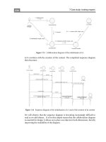
In Figure 2.21, a router has three LAN connections and one WAN connection to the Internet.
Users on the Sales LAN should not have access to the Finance LAN, but they should be able to
access the Internet and the marketing department. The Marketing LAN needs to access the
Finance LAN for application services.
FIGURE 2.21 IP access list example with three LANs and a WAN connection
On the Acme router, the following standard IP access list is configured:
Acme#config t
Acme(config)#access-list 10 deny 172.16.40.0 0.0.0.255
Acme(config)#access-list 10 permit any
It’s very important to know that the any command is the same thing as saying the following
using wildcard masking:
Acme(config)#access-list 10 permit 0.0.0.0
255.255.255.255
Because the wildcard mask says that none of the octets are to be evaluated, every address
matches the mask. So this is functionally the same as using the any keyword.
At this point, the access list is configured to deny source addresses from the Sales LAN access
to the Finance LAN, and allow everyone else. But remember, no action will be taken until the
access list is applied on an interface in a specific direction. But where should this access list be
placed? If you place it as an incoming access list on E0, you might as well shut down the Ethernet
Lab_A
Internet
S0/0
E0Sales E2 Marketing
E1
Finance
4309c02.fm Page 202 Friday, October 24, 2003 2:55 PM
2.10 Implement Access Lists
203
interface because all of the Sales LAN devices will be denied access to all networks attached to the
router. The best place to apply this access list is on the E1 interface as an outbound list.
Acme(config)#int e1
Acme(config-if)#ip access-group 10 out
This completely stops traffic from 172.16.40.0 from getting out Ethernet 1. It has no effect
on the hosts from the Sales LAN accessing the Marketing LAN and the Internet, because traffic
to those destinations doesn’t go through interface E1.
Controlling VTY (Telnet) Access
You’ll probably have a difficult time trying to stop users from telnetting to a large router
because any active interface on a router is fair game for VTY access. You could try to create an
extended IP access list that limits Telnet access to every IP address on the router, but if you did
that, you’d have to apply it inbound on every interface, and that really wouldn’t scale well to
a large router with tens, even hundreds of interfaces, now would it? No worries—here’s a much
better solution. Use a standard IP access list to control access to the VTY lines.
Why does this work? Because when you apply an access to the VTY lines, you don’t need to
specify the Telnet protocol because access to the VTY implies terminal access. You also don’t
need to specify a destination address, since it really doesn’t matter which interface address the
user used as a target for the Telnet session. You really only need to control where the user is
coming from—in other words, the source IP address. Nice!
To perform this function, follow these steps:
1. Create a standard IP access list that permits only the host or hosts you want to be able to
telnet into the routers.
2. Apply the access list to the VTY line with the access-class command.
Here is an example of allowing only host 172.16.10.3 to telnet into a router:
Lab_A(config)#access-list 50 permit 172.16.10.3
Lab_A(config)#line vty 0 4
Lab_A(config-line)#access-class 50 in
Because of the implied deny any at the end of the list, the access list stops any host from tel-
netting into the router except the host 172.16.10.3, regardless of which individual IP address on
the router is used as a target.
Extended Access Lists
In the standard IP access list example, notice how you had to block all access from the Sales
LAN to Finance. What if you needed Sales to gain access to a certain server on the Finance LAN,
but not to other network services for security reasons? With a standard IP access list, you can’t
allow users to get to one network service and not another. Said another way, when you need to
make decisions based on both source and destination addresses, a standard access list won’t allow
4309c02.fm Page 203 Friday, October 24, 2003 2:55 PM