Tony Bourke Server Load Balancing phần 4 pdf
Bạn đang xem bản rút gọn của tài liệu. Xem và tải ngay bản đầy đủ của tài liệu tại đây (557.08 KB, 19 trang )
Multipurpose Devices
49
you'll probably need your own Layer 2 switches, but you will not need a router
since the colocation company would provide this. Since it's much more cost effec-
tive to aggregate several clients off of a router port rather than dedicate a port to
each customer, most providers use Layer 2 switches to distribute router-port traffic
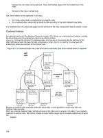
(see Figure 5-11). A client's Layer 2 switch would plug directly into the provider's
Layer 2 switch, resulting in a configuration known as the "six pack" (two routers,
two colocation provider switches, and two client switches). VRRP or similar proto-
cols provide the redundancy on the routers.
Figure 5-11. Six-pack design
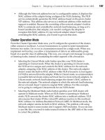
To prevent a bridging loop (shown in Figure 5-12), some form of port blocking
must be done on one of the ports to prevent multiple Layer 2 paths from existing.
Spanning-Tree Protocol (STP) is a protocol that can take care of this automati-
cally. Each port has a cost associated with it, with the lowest cost being preferred.
If STP detects multiple paths, it shuts off all but the highest priority port (with the
lowest number). It can be set up on the provider's end, the site's end, or both.
Figure 5-13 shows an example of STP on the provider's right switch blocking the
path between the provider's right switch and the site's right switch.
Multipurpose Devices
It is now possible—and even advantageous—to merge two or more typically sepa-
rate functions into one. For example, a multitude of Layer 2/3 switches on the
market incorporate the port capacity and Layer 2 functionality of a switch with the
Layer 3 routing functions of a router. With the switch-based load balancers, incor-
porating Layer 4/5-7 with Layer 2/3 functionality is also possible. For the purposes
50
Chapter 5: Introduction to Architecture
Figure 5-13. Six pack with STP blocking
of this book, however, I'll keep devices and their layered functions separate. For
example, a Layer 2 device will be only a Layer 2 device. This is to keep things
simple and easy to follow. This is not to say that combining them is not possible—
or even not advantageous—but that they are simpler to understand when kept
separate.
Figure 5-12. Six-pack bridging loop
Cast of Characters 57
Cast of Characters
To keep things simple, several network components appear throughout the rest of
this book. Components such as web servers and IP addresses remain constant,
even though the topology or products may change. This keeps things easy to
follow and allows for comparisons between different topologies and products.
Every show needs its cast, so let me introduce you to the players.
Server Load Balancers
Since this book is about server load balancing, I am going to need load balancers.
I will need two devices, as I am going to incorporate the high-availability func-
tions. I call these load balancers lb-1 and lb-2, regardless of the vendors they rep-
resent.
Networks
Since load balancers are network-based, I need networks to configure them. So
that O'Reilly & Associates, Inc. and I don't receive email from angry network
administrators regarding their network IPs, I use private IP address space defined
in RFC 1918. These are not publicly routed IP addresses, so anyone can use them
for his own internal private network. These networks include:
10.0.0.0-10.255.255.255
172.16.0.0-172.16.255.255
192.168.0.0-192.168.255.255
I use a /24 (256 IP addresses) worth of these nonrouted IPs in the example net-
work designs. A block of IP addresses is called a netblock, which is just another
word for a subnet.
Outside network
192.168.0.0/24 represents a publicly accessible and routable Class C worth of IP
address space. This is the type of network on which a load-balanced VIP would
be configured. As far as Layer 2 VLANs are concerned, the outside network is
referred to as VLAN 1. Remember, while using this nonrouted netblock to repre-
sent a public network, your individual IP addresses depend on your network or
network provider.
Internal network
10.0.0.0/24 represents a nonrouted IP address range used for some of the network
topologies that I discuss later. Nonrouted IP addresses are advantageous because
they provide an extra layer of security by making the servers difficult or impossible
52
Chapter 5: Introduction to Architecture
to access from the Internet. If a hacker is unable to reach your servers, she is
unable to hack them. Even in your own network configuration, where the outside
network consists of real IP addresses, the internal network is still composed of the
nonrouted private RFC 1918 addresses (though not necessarily the subnet speci-
fied).
Web Servers
Since I am talking about implementing Server Load Balancing, I need servers to
load balance. I call these web servers, since web serving is the most common use
of SLB. However, SLB can be used with FTP, SMTP, POP3, media streaming, and
many other network-based protocols.
The servers are given the prefix of ws (web server) and are known as ws-1, ws-2,
ws-3, etc. They are assigned IP addresses from either the outside or internal net-
work, depending on the network topology. When necessary, each web server has
a network configuration table (see Table 5-1), which tells how to configure the
basic IP stack of each device. Included is the default route for the web server,
which is crucial to the operation of SLB because it controls the flow of outbound
traffic.
Table 5-1. Web server configuration
Server name IP address Subnet mask Default gateway
ws-1
10.0.0.100
255.255.255.0 10.0.0.1
Routers
A redundant pair of routers provides connectivity to the outside world. VRRP (or
HSRP with Cisco routers) runs between the routers to provide high availability in
case one should fail. A pair of Layer 2 switches, discussed next, aggregates the
Internet traffic. The routers are named r-1 and r-2. They are configured as shown
in Table 5-2.
Router
r-1
r-2
IP address
192.168.0.2
192.168.0.3
Subnet mask
255.255.255.0
255.255.255.0
VRRP shared address
192.168.0.1
192.168.0.1
Each router has an individual IP address and a shared VRRP address. The IP
address is active on only one router at a time, thus having the same active-standby
scenario that server load balancers do. Should a router fail, the IP would be picked
up by the standby unit.
Table 5-2. Router configuration
Cast of Characters 53
Switches
In all the network scenarios, a pair of Layer 2 switches is employed. Switches are
the network devices that interconnect all of the devices (routers, server load bal-
ancers, servers, etc.) to aggregate the traffic. Since we are talking high availability,
we employ a pair for redundancy. We use spanning-tree protocol to provide this
Layer 2 redundancy. We call the switches sw-1 and sw-2. They can be configured
with IPs on the network, but this isn't necessary. Given that most switches only
support telnet (as opposed to an encrypted protocol such as SSH or Kerberos) and
the given security implications, we leave them without IPs for now. Your own spe-
cific network needs will decide how to network them safely.
Flat-Based SLB
Network Architecture
A flat-based SLB network architecture is, by definition, any SLB network imple-
mentation where the IPs of the VIPs and the IPs of the real servers are on the
same subnet. It is named for the flatness of the network architecture because all
the network components are on a single subnet.
Implementation
Flat-based is the simpler of the two SLB methods, the other method being NAT-
based SLB. Flat-based works on a single subnet without translation into another
subnet. While it is true that NAT is performed in most SLB scenarios (the only SLB
scenario where NAT is not performed is DSR), since the load balancer isn't trans-
lating from one subnet to another, this method is not referred to as NAT.
Figure 6-1 shows the basic premise of flat-based SLB with simple connectivity into
the Layer 2 infrastructure and the same subnet IP scheme. There are a few varia-
tions of flat-based SLB, but this is a simple and accurate representation.
Why Flat-Based?
There are several advantages to using the flat-based network, the main one being
its simplicity. Flat-based is easier to manage, visualize, and design around, which
keeps in line with the KISS philosophy.
Access to and from the outside network is always a concern with SLB, and with
networks in general. With flat-based SLB, the servers have access to the outbound
to the network without any special configurations such as reverse-NATs. There
also isn't any extra configuration needed to access the web servers individually.
Most sites have an administrative need to view each server separately from the
load-balanced VIP, which isn't a problem for flat-based SLB.
54
6
Implementation
55
Figure 6-1. Simple, flat-based SLB
Flat-based SLB is ideal when a firewall has been implemented in front of the load
balancers to take care of security requirements. While NAT-based is sometimes
used as an additional security measure, when a firewall is present those measures
are not required.
Flat-based SLB is also ideal for use with DSR. The load balancers can hang off the
Layer 2 infrastructure, take the inbound traffic, and the outbound traffic flows right
back out through the router or firewall. While DSR is possible with NAT-based
SLB, it requires more equipment and is much more complicated to implement.
Streaming and FTP applications are often better served with flat-based SLB. One
reason for this is that flat-based is ideal for DSR and, given the high traffic ratios
(such as 200 packets out for every packet in), DSR can save quite a bit of
resources on the load balancer by not having it process the 200 packets out, but
only the 1 packet in. Also, some types of streaming applications don't handle NAT
very well and need to have publicly routed IP addresses for the servers.
Route-Path, Bridge-Path, and DSR
Flat-based SLB can work equally easily with the route-path, bridge-path, and DSR
methods of return-path. In Figure 6-2 we see a very typical installation (one used
many times in the product configuration guides later in this book) involving route-
path.
This is a flat-based, route-path, one-armed architecture. The load balancers are the
default routes for the servers, even though they are on the same subnet as the
router and are one-armed to the Layer 3 infrastructure. This ensures that the
packets flow through the load balancer on the way out. To implement DSR on all
or a just a portion of the site, only a configuration change is needed. Topology
changes are not necessary.
Web Server
192.168.0.100
Layer 2 switch
56
Chapter 6: Flat-Based SLB Network Architecture
Web Server
(ws-1)
192.168.0.100
Web Server
(ws-2)
192.168.0.101
Web Server
(ws-3)
192.168.0.102
Web Server
(ws-4)
192.168.0.103
Figure 6-2. Flat-based, route-path, one-armed SLB
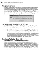
In Figure 6-3, we see a flat-based configuration using bridge-path instead of route-
path. In this situation, the load balancers are in the Layer 2 path of the traffic flow.
Some products support only bridge-path, others support route-path, and a few
products support both methods. There are several advantages to using the route-
path method, including the ability to have several load balancers operating on a
network. With the bridge-path method, only one pair of load balancers can be uti-
lized. Any more load balancer sets may create a Layer 2 bridging loop. Also, DSR
does not work with bridge-path, as the load balancer is in the Layer 2 path. Since
there can be only one Layer 2 path (more than one Layer 2 path would create a
nasty bridging loop), it's not possible to bypass the load balancer on the way out.
There are variations on the basic implementations of flat-based SLB, but for the
most part, they conform to the previous examples. To decide on the best method,
it's best to look at your overall needs and requirements, as well as the capabilities
of the product.
Layer3 router
(r-2)
192.168.0.2
Standby
Layer3 router
(r-1)
192.168.0.2
Active
Traffic Flow
57
Web Server
(ws-1)
192.168.0.100
Web Server
(ws-2)
192.168.0.101
Web Server
(ws-3)
192.168.0.102
Web Server
(ws-4)
192.168.0.103
Figure 6-3. Flat-based, bridge-path, two-armed SLB
Traffic Flow
To understand how flat-based SLB works, let's take the example of a user with an
IP address of 208.185.43.202. Table 6-1 illustrates the changes in IP source and
destination addresses. The process takes four steps:
1. The user initiates an HTTP connection by typing the host name of vip-1 (192.
168.0.200) into the browser. The connection goes to the load balancer.
2. The load balancer takes the packet and rewrites the destination address,
leaving the source address alone. The load balancer decides which server to
send the connection to, and changes the destination address to 192.168.0.100,
which would be the web server ws-1.
58
Chapter 6: Flat-Based SLB Network Architecture
3. The web server responds and sends traffic back to 208.185.43.202. The traffic
passes through the load balancer, since it is the web server's default route.
4. The load balancer rewrites the packet on the way out with the source address
192.168.0.200. The packet travels back to the user and completes the journey.
Step Source IP address Destination IP address
1
2
3
4
208.185.43.202
208.185.43.202
192.168.0.100
192.168.0.200
192.168.0.200
192.168.0.100
208.185.43.202
208.185.43.202
Flat-Based Setup
The following sections outline some basic IP configurations to be used as an
example for setup and installation of a flat-based SLB network. The redundancy
and wiring are typical for this type of scenario, but are by no means the only way
to implement an SLB site. These configuration examples are used in the chapters
involving specific vendor configuration.
Routers
The routers are set up in a redundant fashion. Each unit backs up the other unit.
One unit is the active unit, while the other is the standby. In Table 6-2, r-1 is the
active unit with a VRKP priority of 200, while r-2 is the standby with a VRRP pri-
ority of 100.
Table 6-2. Router network configuration
Unit
IP address
Subnet mask
VRRP IP address
VRRP priority
r-1 (active)
192.168.0.2
255.255.255.0
192.168.0.1
200
r-2 (standby)
192.168.0.3
255.255.255.0
192.168.0.1
100
SLB Units
The SLB units in Table 6-3 are configured on the same subnet as the routers and
web servers. They each have their own IP addresses, as well as a shared IP
address for redundancy. The active unit (determined through VRRP, fail-over
cable, or some other method) is the unit with the shared IP address, while the
other unit waits to take the IP if the active unit should fail. They each have a
single connection to the Layer 2 infrastructure.
Table 6-1. Packet translation
Flat-Based Setup
59
Table 6-3. SLB network configuration
Unit
IP address
Subnet mask
Shared address
Default route
lb-1 (active)
192.168.0.11
255.255.255.0
192.168.0.10
192.168.0.1
lb-2 (standby)
192.168.0.12
255.255.255.0
192.168.0.10
192.168.0.1
Web Servers
While the web servers are on the same subnet as the routers, their default route is
the load balancer's shared IP (see Table 6-4). This is so that traffic is rewritten on
the way back out to the Internet.
Table 6-4. Web server network configuration
Unit
IP address
Subnet mask
Default route
Service and port
ws-1
192.168.0.100
255.255.255.0
192.168.0.10
HTTP:80
ws-2
192.168.0.101
255.255.255.0
192.168.0.10
HTTP:80
ws-3
192.168.0.102
255.255.255.0
192.168.0.10
HTTP:80
ws-4
192.168.0.103
255.255.255.0
192.168.0.10
HTTP:80
VIPs
The VIP is configured with a publicly routable IP address and this is the address
the Internet uses to access the load-balanced site (see Table 6-5). Since the indi-
vidual web servers are on the same subnet, you can access them directly without
involving extra VIPs configured on the load balancers.
Table 6-5. VIP configuration
VIP
vip-1
IP address
Subnet mask
Service and port
Real servers active
192.168.0.200
255.255.255.0
HTTP:80
ws-1, ws-2, ws-3, ws-4
Redundancy
Flat-based SLB can use either route-path or bridge-path, so redundancy can occur
on Layer 2 or Layer 3, depending on the method implemented. When using route-
path, a Layer 2 redundancy is required. STP is almost never used since it can take
10 seconds or more to react. Typically, a proprietary variation of a hot-standby
60 Chapter 6: Flat-Based SLB Network Architecture
protocol is used, which quickly switches between active and standby units (in sec-
onds or milliseconds), while still protecting a network against a bridging loop.
Security
Security measures are critical for flat-based SLB implementations because the load
balancer does not usually have direct control over traffic destined for the servers.
Without a firewall or other packet-filtering scheme, servers and load balancers—as
well as VIPs and real servers on the same subnet—are open to malicious attack.
This is not an acceptable security model for most sites, so you must find a way to
protect your web server from hacking or attack.
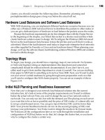
One way to protect individual web servers is to place a firewall between the
Internet-connected routers and the load balancers. A firewall would provide the
packet filtering, stateful inspection, intrusion detection, and other measures neces-
sary to adequately protect the network. Figure 6-4 shows an example of this secu-
rity scheme involving flat-based SLB and a redundant set of firewalls.
One drawback of most firewall products is that they often have a traffic limit of
about 70 to 80 Mbps, depending greatly on the firewall itself and on the type of
traffic generated (streaming versus HTTP traffic, for instance). If the firewall
product itself is not the limit, then the 100 Mbps Fast Ethernet interface could be,
since many firewalls today do not have Gigabit Ethernet. This creates a potential
bottleneck in an architecture that could otherwise easily support hundreds of
Mbps worth of traffic.
Access lists on a router that connects the network to the load balancer are another
option, but in hosting environments, it is often impossible to implement ACLs on a
provider's equipment. Also, ACLs may not fulfill all of a site's security require-
ments.
Firewall Load Balancing (FWLB) is another solution. FWLB involves distributing
the network load among a group of firewalls, in much the same manner that SLB
distributes load among several servers. The drawback is that FWLB has a fairly
complicated setup, requiring several switches/VLANs and four separate FWLB load
balancers for complete redundancy. Most vendors that offer an SLB solution also
offer FWLB solutions, often with the same equipment as SLB.
The best way to handle site security is to look at the site's throughput and secu-
rity needs, and to create a solution accordingly. A site's design and administration
team is ultimately responsible for the site.
Security
61
Figure 6-4. Flat-based SLB with a firewall
NAT-Based SLB
Network Architecture
NAT-based SLB network architecture is, by definition, any SLB network implemen-
tation where the IPs of the VIPs and real servers are on different subnets. It is
named NAT because the load balancer NATs packets traveling between two sub-
nets, much like a firewall or a router performing a NAT.
Implementation
The main difference between NAT- and flat-based architectures is that the SLB unit
performs a NAT from one network to another. The best and most typical way to
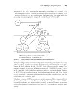
implement NAT-based SLB is with a route-path, two-armed configuration. In
Figure 7-1, the SLB device translates normal routed IP addresses (represented by
the nonrouted 192.168.0.0/24 IP space) into nonrouted IPs, on which the web
servers sit.
In this configuration the servers are on a separate VLAN from the VIP addresses on
the load balancers. On the public network, the only floating IPs between the
active and standby load balancers are the VIP addresses. There is no need for a
floating default gateway (such as 192.168.0.10 in the flat-based example) on the
public network, since the load balancers aren't acting as default routes on that net-
work. The floating gateway is included on the private network (10.0.0.1 in the fol-
lowing figures). The load balancers can also function as firewalls because they
have such tight control over traffic flow.
Sometimes NAT-based SLB is implemented, but, in this method, all devices share
one LAN. The load balancers are configured for multiple networks on the same
LAN, and they perform the NAT themselves. We see this type of configuration in
Figure 7-2.
62
7
Implementation
63
Figure 7-1. NAT-based, route-path, two-armed SLB
The load balancers are configured for two subnets on the same LAN, one for the
public interfaces for the VIPs, and another for the web server's private subnet.
Even though everything is on the same LAN, the load balancer still performs the
NAT.
From both a security and an architectural standpoint, it's better to use a two-armed
configuration with two separate LANs (or two VLANs). Putting everything on one
LAN defeats several of the security objectives and advantages of a NAT-based con-
figuration. Keeping an actual barrier between the server and public network rein-
forces the overall security of a site. Traffic flow is easier to manage with two
64
Chapter 7: NAT-Based SLB Network Architecture
Web Server Web Server
(ws-1) (ws-2)
192.168.0.100 192.168.0.101
Web Server
(ws-3)
192.168.0.102
Web Server
(ws-4)
192.168.0.103
Figure 7-2. NAT-based, route-path, one-armed SLB
(V)LANs as well. There is a clear delineation and demarcation point for the two
separate networks, making troubleshooting, in many cases, much easier.
Bridge-Path and DSR
Because NAT from one network to another is a Layer 3 function, bridge-path isn't
an option for NAT-based SLB. For NAT to work, the load balancer must have inter-
faces on two networks, and bridge-path generally involves only one network.
DSR is not as common in a NAT-based scenario as it is in a flat-based setup, but it
is possible. Unlike flat-based scenarios, a Layer 3 device is required in addition to
the load balancer and Layer 2 infrastructure to work with DSR. As per a DSR sce-
nario, the packets have already been rewritten on the way out of the actual servers
with no need for any more processing. The Layer 3 device simply forwards the
Implementation
65
packets from one network to another—a process that is resource-intensive but
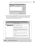
saves the load balancer some work. In Figure 7-3, we see an example of a NAT-
based configuration with DSR.
Figure 7-3. NAT-based network topology with DSR
The redundancy component was removed to better show how DSR would fit into
this type of scenario. A packet comes to the load balancer (step 1) and is sent to a
web server, such as ws-3 (step 2). The web server then sends the packet out
already rewritten (step 3), but it still needs to be forwarded to the public network
so it can get to the Internet. The Layer 3 device forwards the packet unchanged to
the public network and then on to its destination (step 4), without adding any
additional load to the load balancer. The actual load on the Layer 3 device is min-
imal, since all it is doing is forwarding packets with no processing.
Why NAT-Based?
There are several advantages to NAT-based SLB, most of which involve the extra
security that a NATed connection can provide, especially when the servers are on
66
Chapter 7: NAT-Based SLB Network Architecture
a nonrouted RFC 1918 address space. When dealing with servers on a nonrouted
IP space, you have a great deal of control over how the servers are actually seen
by the world.
This architecture lends itself well to a site where the majority of traffic is HTTP (or
SSL). With the added security of the NATed IPs and the relatively low in-out ratio
(approximately 10 packets out for every packet in with HTTP traffic, while hun-
dreds of packets go out for every packet in with streaming), the NAT-based archi-
tecture can provide an additional measure of security and performance. Web and
SSL applications both work well with NAT.
Traffic Flow
To understand how flat-based SLB works, let's take the example of a user with an
IP address off 200.200.200.20. Table 7-1 illustrates the changes in IP source and
destination addresses. The process takes four steps:
1. The user initiates an HTTP connection by typing the domain name of vip-1
(192.168.0.200) into the browser. The connection goes to the load balancer.
2. The load balancer takes the packet and rewrites the destination address,
leaving the source address as it is. The new destination address is 10.0.0.100,
which would be the web server ws-1.
3. The web server responds and sends traffic back to 200.200.200.20. The traffic
passes through the load balancer, as it is the web server's default route.
4. The load balancer rewrites the packet on the way out with the source address
192.168.0.200. The packet travels back to the user and completes the journey.
Table 7-1- Packet translation
Step
1
2
3
4
Source IP address
200.200.200.20
200.200.200.20
10.0.0.100
192.168.0.200
Destination IP address
192.168.0.200
10.0.0.100
200.200.200.20
200.200.200.20
Network Configuration
The following sections outline some basic IP configurations that may be used as
examples for setup and installation of NAT-based SLB networks. The redundancy
and wiring are typical for this type of scenario but are by no means the only ways
to implement an SLB site. These configuration examples are used in the chapters
involving specific vendor configurations.
Network Configuration
67
Routers
The routers are configured exactly as in the flat-based topology (see Table 7-2).
Two routers, one active and one standby, are configured with a floating IP address
between them. The active unit is given a VRRP priority of 200, while the standby is
given 100.
Table 7-2. Router network configuration
Unit
IP address
Subnet mask
VRRP IP address
VRRP priority
r-1 (active)
192.168.0.2
255.255.255.0
192.168.0.1
200
r-2 (standby)
192.168.0.3
255.255.255.0
192.168.0.1
100
SLB Units
The SLB units are configured a bit differently in Table 7-3. The VLAN 1 configura-
tion is identical to the flat-based network architecture, while in the NAT architec-
ture, there is a whole other network configured on VLAN 2. Different products
have different ways of denoting which interfaces are outside and which are
internal. Switch-based load balancers allow you to set VLANs, while server-based
load-balancers usually have those roles labeled in their Ethernet interfaces.
Table 7-3. SLB network configuration
Unit
IP address (VLAN 1)
Subnet mask
Shared address
Default route
IP address (VLAN 2)
Subnet mask
Shared address
lb-1 (active)
192.168.0.11
255.255.255.0
192.168.0.10
192.168.0.1
10.0.0.2
255.255.255.0
10.0.0.1
lb-2 (standby)
192.168.0.12
255.255.255.0
192.168.0.10
192.168.0.1
10.0.0.3
255.255.255.0
10.0.0.1
You may notice a similar numbering and configuration scheme of VLAN 2 to the
routers r-1 and r-2. This is because the SLB units are acting as routers and are the
default gateways for all web servers. Because of the similar function, it simplifies
matters greatly to configure them like the routers.
Again, notice that there is no floating default route between the two load bal-
ancers on the public VLAN, while a shared IP is on the private VLAN. Since there
are no servers on the public VLAN, there isn't a need for the load balancers to
serve as a default route on that network.