Beginning AutoCAD 2002 Episode 6 doc
Bạn đang xem bản rút gọn của tài liệu. Xem và tải ngay bản đầy đủ của tài liệu tại đây (1.23 MB, 30 trang )
4 Note
When grips were first introduced into AutoCAD, the terms warm and hot were used,
meaning:
a) Warm grip: appear as blue boxes and the selected objects are highlighted – dashed
appearance as fig. (a). The grip options cannot be used in this state.
b) Hot grip: appear as solid red boxes when a cold or warm box is ‘picked’ as fig. (c).
The selected hot grip acts as the base grip and the grip options can be used.
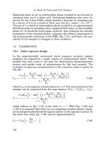
Grip exercise 1
This demonstration is relatively simple but rather long. It is advisable to work through
the exercise without missing out any of the steps.
1 Erase all objects from the screen, or re-open A:A3PAPER.
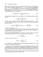
2 Refer to Fig. 22.3 and draw the original shape using the sizes given as fig. (a). Make the
lower left corner at the point (100,100) and ensure grips are on.
3 Move the cursor to the circle and pick it, then move to the right vertical line and pick
it. Blue grip boxes appear and the two objects are highlighted – fig. (b).
Grips 143
Figure 22.3 Grip exercise 1.
Beginning with AutoCAD 2002.qxd 14/06/2002 19:06 Page 143
4 Move the cursor grip box to the grip box at the circle centre and left-click, i.e. pick it.
The selected box will be displayed in red as it is now the base grip – fig. (c). Observe the
command line:
prompt ** STRETCH **
Specify stretch point or [Base point/Copy/Undo/eXit]
respond with a <RETURN>
prompt ** MOVE **
Specify move point or [Base point/Copy/Undo/eXit]
enter @25,25 <R>
5 The following should have happened:
a) the circle and line are moved
b) the command prompt line is returned
c) the grips are still active
d) there is no base grip – fig. (d).
6 Move the cursor and pick the text item to add it to the grip selection – fig. (e).
7 Make the grip box of the text item the base grip, by moving the cursor pick box onto it,
left-clicking as fig. (f), and:
prompt ** STRETCH **
Specify stretch point or [Base point/Copy
respond with a <RETURN>
prompt ** MOVE **
Specify move point or [Base point/Copy
respond <RETURN>
prompt ** ROTATE **
Specify rotation angle or [Base point/Copy
enter 90 <R>
8 The circle, line and text item will be rotated and the grips are still active – fig. (g).
9 Make the same text item grip box the base grip (easy!) and:
prompt **STRETCH**
Specify stretch point or
enter SC <R> – the scale grip option
prompt ** SCALE **
Specify scale factor or [Base point
enter 0.5 <R>
10 The three objects are scaled and the grips are still active as fig. (h).
11 Make the right box on the line hot and:
prompt **STRETCH**
enter MI <R> – the mirror option
prompt ** MIRROR **
Specify second point or [Base point
enter B <R> – the base point option
prompt Specify base point
respond Midpoint icon and pick the original horizontal line
prompt ** MIRROR **
Specify second point or
respond Midpoint icon and pick the arc.
12 The three objects are mirrored about the selected ‘line’ and the grips are still active
(warm) – fig. (i).
13 Press ESC – removes the grips and ends the sequence
14 The exercise is now complete. Do not exit yet.
144 Beginning AutoCAD 2002
Beginning with AutoCAD 2002.qxd 14/06/2002 19:06 Page 144
Selection with grips
Selecting individual objects for use with grips can be tedious. It is possible to select a
window/crossing option when grips are on.
1 Your screen should display the line, circle and text item after the grips exercise has been
completed?
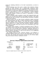
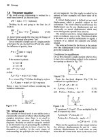
2 Refer to Fig. 22.4(a), move the cursor and pick a point ‘roughly’ where indicated. Move
the cursor down and to the right, pick a second point and all complete objects within
the window will display grip boxes with highlighted objects, i.e. warm.
3 ESC to cancel the grip effect.
4 Move the cursor to about the same point as step 2, and pick a point – Fig. 22.4(b), then
move the cursor upwards and to the left and pick a second point. All objects within or
which cross the boundary will display grip boxes with highlighted objects.
5 ESC to cancel grip selection.
6 The effect can be summarised as:
a) window effect to the right of first pick
b) crossing effect to the left of the first pick.
Grips 145
Figure 22.4 Window/crossing selection with grips.
Beginning with AutoCAD 2002.qxd 14/06/2002 19:06 Page 145
Grips exercise 2
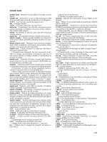
1 Open C:\BEGIN\USEREX to display the component used in the offset and text exercises
and refer to Fig. 22.5.
2 Ensure only the red objects displayed – fig. (a).
3 Grips on?
4 Pick a point 1 and drag out a window and pick a point 2. Five lines will display grip
boxes and be highlighted as fig. (b).
5 Make the rightmost grip the base grip and:
prompt ** STRETCH **
respond right-click to display the grip options
then pick Rotate
prompt Specify rotation angle or
enter 180 <R>
6 Now ESC to cancel the grips – fig. (c).
7 Pick a point 3 and drag out a crossing window and pick a point 4 to display five
highlighted lines with grip boxes as fig. (d).
8 Make the lowest grip box on the right vertical line hot and:
prompt ** STRETCH **
respond right-click to display the grip options menu
then pick Move
prompt Specify move point or
respond Endpoint icon and pick line K.
146 Beginning AutoCAD 2002
Figure 22.5 Grip exercise 2.
Beginning with AutoCAD 2002.qxd 14/06/2002 19:06 Page 146
9 The lines are moved ‘onto’ the rotated lines – fig. (e).
10 ESC to cancel the grips.
11 Pick one of the inclined lines and:
a) make the lowest grip box the base grip
b) activate the STRETCH option
c) stretch the grip box perpendicular to line P
d) repeat for the other inclined line
e) final result – fig. (f).
12 Note: this exercise could have been completed using the modify commands, e.g. rotate
and trim. It demonstrates that there is no one way to complete a drawing.
13 Save this exercise if required, but not as USEREX.
Assignment
Activity 15 involves the re-positioning of a robotic arm, which has proved relatively
successful in my previous ‘Beginning’ books.
1 Create the robotic arm in the original position using the sizes given – fig. (a). Use your
discretion for sizes not given.
2 Upper arm rotate by 45 degrees – fig. (b).
Two circles and two lines need to be ‘picked’ with the base grip at the larger circle centre.
3 Both arms mirrored about line through large circle centre.
Two more lines and a circle added to the grip selection as fig. (c).
4 Both arms rotated to a horizontal position – fig. (d).
5 Finally – fig. (e) – three grip operations:
a) lower arm stretch by 50
b) upper arm move
c) upper arm rotate.
6 Save when completed.
Summary
1 Grips allow the user access to the STRETCH, MOVE, ROTATE, SCALE and MIRROR
modify commands without icon or menu bar selection.
2 Grips work in the ‘opposite sense’ from the normal AutoCAD commands, i.e. select object
first then the command
3 Grips do not have to be used. They give the user another draughting tool.
4 Grips are toggled on/off using the Grips dialogue box or by keyboard entry. The dialogue
box allows the grip box colours and size to be altered.
5 Grip states are warm or hot.
6 If grips are not being used, I would always recommend that they be toggled off, i.e.
GRIPS: 0 at the command line.
7 When a grip box is the base grip, the options can be activated by:
a) return at the keyboard
b) entering SC, MO, MI, etc.
c) right-click the mouse to display the grip option menu.
Grips 147
Beginning with AutoCAD 2002.qxd 14/06/2002 19:06 Page 147
Drawing assistance
Up until now, all objects have been created by picking points on the screen, entering
coordinate values or by referencing existing objects, e.g. midpoint, endpoint, etc.
There are other methods which enable objects to be positioned on the screen, and in this
chapter we will investigate three new concepts, these being:
a) point filters
b) construction lines
c) ray lines.
Point filters
This allows objects to be positioned by referencing the X and Y coordinate values of
existing objects.
Example 1
1 Open the A3PAPER standard sheet and refer to Fig. 23.1
2 Draw a 50 side square, lower left corner at 20,220. Grips off
3 Multiple copy this square to three other positions
4 A circle of diameter 30 has to be created at the ‘centre’ of each square and this will be
achieved by four different methods:
a) Coordinates
Activate the circle command with centre: 45,245; radius: 15
b) Object snap midpoint
– draw in a diagonal of the square, then pick the circle icon
– pick the centre icon
– centre point: snap to Midpoint of diagonal
– radius: enter 15.
c) Object snap from
– pick the circle icon
– centre: pick the snap from icon
– base point: endpoint icon and pick left end of line AB
– offset: enter @25,25
– radius: enter 15.
d) Point filters
Activate the circle command and:
prompt Specify center point
enter X <R>
prompt of
respond Midpoint icon and pick line PQ
prompt (need YZ)
respond Midpoint icon and pick line PR
prompt Specify radius and enter: 15 <R>
Chapter 23
Beginning with AutoCAD 2002.qxd 14/06/2002 19:06 Page 148
Example 2
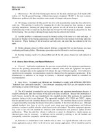
Figure 23.1 displays the top, end and isometric views of a shaped block. The front view
has to be created from the two given views, and we will use the point filter technique
to achieve this.
1 Draw the top and end views using the sizes given. Use the lower part of the screen. Draw
with the snap on.
2 Select the line icon and:
prompt Specify first point
enter .X <R>
prompt of
respond Intersection icon and pick point A
prompt (need YZ)
respond Intersection icon and pick point K
and cursor ‘snaps’ to a point on the screen
prompt Specify next point
enter .X <R>
prompt of
respond Intersection icon and pick point B
prompt (need YZ)
respond Intersection icon and pick point L – line 1 is drawn
prompt Specify next point
enter .X <R> and: Intersection of point C
prompt (need YZ) and: Intersection of point L – line 2 is drawn
prompt Specify next point
Drawing assistance 149
Figure 23.1 Point filter examples.
Beginning with AutoCAD 2002.qxd 14/06/2002 19:06 Page 149
enter .X <R> and: Intersection of point C
prompt (need YZ) and: Intersection of point M – line 3 is drawn
prompt Specify next point
enter .X <R> and: Intersection of point D
prompt (need YZ) and: Intersection of point K – line 4 is drawn
prompt To point and: C <R> to draw line 5.
3 The front view of the shaped block is now complete.
4 This exercise does not need to be saved.
5 Note
a) The point filter method of creating objects can be rather ‘cumbersome’ to use. Point
filters are another aid to draughting.
b) I would suggest that Object Snap Tracking is ‘easier’ than point filters fro creating
the front view in this exercise?
Construction lines
Construction lines are lines that extend to infinity in both directions from a selected point
on the screen. They can be referenced to assist in the creation of other objects.
1 Open the A3PAPER standard sheet, layer OUT current and display toolbars Draw, Modify
and Object Snap. Refer to Fig. 23.2(a).
2 With layer OUT current, draw:
a) a 100 sided square, lower left corner at 50,50
b) a circle, centred on 250,220 with radius 50.
150 Beginning AutoCAD 2002
Figure 23.2 Construction and ray lines.
Beginning with AutoCAD 2002.qxd 14/06/2002 19:06 Page 150
Drawing assistance 151
3 Make a new layer (Format-Layer) named CONLINE, colour to suit and with a DASHED
linetype. This layer is to be current.
4 Menu bar with Draw-Construction Line and:
prompt Specify a point or [Hor/Ver/Ang/Bisect/Offset]
enter 50,50 <R>
and line ‘attached’ to cursor through the entered point and ‘rotates’ as the mouse
is moved
prompt Specify through point
enter 80,200 <R>
prompt Specify through point
respond Center icon and pick the circle
prompt Specify through point and right-click.
5 At the command line enter XLINE <R> and:
prompt Specify a point or
enter H <R> – the horizontal option
prompt Specify through point
enter 100,20 <R>
prompt Specify through point
respond Midpoint icon and pick a vertical line of square
prompt Specify through point
respond Quadrant icon and pick top of circle
prompt Specify through point and right-click.
6 Select the CONSTRUCTION LINE icon from the Draw toolbar and:
prompt Specify a point or
enter V <R> – the vertical option
prompt Specify through point
respond Center icon and pick the circle
prompt Specify through point and right-click.
7 Activate the construction line command and:
prompt Specify a point or
enter O <R> – the offset option
prompt Specify offset distance or [Through] and enter: 75 <R>
prompt Select a line object
respond pick the vertical line through the circle centre
prompt Select side to offset
respond offset to the right
prompt Select a line object
respond offset the same line to the left
prompt Select a line object and right-click.
8 Construction line command and at prompt:
enter A <R> – the angle option
prompt Enter angle of xline (0.0) or [Reference]
enter – 30 <R>
prompt Specify through point
respond Center icon and pick the circle
prompt Specify through point
enter 135,40 <R> then right-click.
Beginning with AutoCAD 2002.qxd 14/06/2002 19:06 Page 151
9 Construction line command for last time and at prompt:
enter B <R> – the bisect option
prompt Specify angle vertex point
respond Midpoint icon and pick top line of square
prompt Specify angle start point
respond pick lower left vertex of square
prompt Specify angle end point
respond Midpoint icon and pick square right vertical line
prompt Specify angle end point and right-click.
10 Construction lines can be copied, moved, trimmed, etc. and object snap referenced to
create other objects. SHAPE1 and SHAPE2 in Fig. 23.2(a) have been ‘drawn’ by
referencing the existing construction lines. Try some shape creation for yourself.
11 Note
a) Think of how construction lines could have been used to create the front view of the
point filters example completed earlier in this chapter.
b) I would recommend that construction lines are created on their own layer, and that
this layer is frozen to avoid ‘screen clutter’ when not in use. I would also recommend
that they are given a colour and linetype not normally used.
12 Task: try the following:
a) At the command line enter LIMITS <R> and:
prompt Specify lower left corner and enter: 0,0 <R>
prompt Specify upper right corner and enter: 10000,10000 <R>
b) From menu bar select View-Zoom-All and:
1. drawing appears very small at bottom of screen
2. the construction lines ‘radiate outwards’ to the screen edges
c) Using LIMITS <R> enter the following values:
lower left corner: –10000,–10000
upper right corner: 0,0
d) View-Zoom-All to ‘see’ the construction lines
e) Return limits to 0,0 and 420,297 then View-Zoom-All to restore the original drawing
screen. A screen regen may be required?
13 The construction line exercise is now complete. The drawing can be saved if required,
but we will not use it again.
Rays
Rays are similar to construction lines, but they only extend to infinity in one direction
from the selected start point.
1 Make a new layer called RAYLINE, colour to suit and with a dotted linetype. Make this
layer current and refer to Fig. 23.2(b).
2 Freeze layer CONLINE and erase any objects to leave the original square and circle.
3 Menu bar with Draw-Ray and:
prompt Specify start point
respond Center icon and pick the circle
prompt Specify through point and enter: @100<150 <R>
prompt Specify through point and enter: @100<0 <R>
prompt Specify through point and enter: @100<–90 <R>
prompt Specify through point and right-click.
4 With layer OUT current, draw three 25 radius circles at the intersection of the ray lines
and circle.
152 Beginning AutoCAD 2002
Beginning with AutoCAD 2002.qxd 14/06/2002 19:06 Page 152
5 Make layer RAYLINE current and at the command line enter RAY <R> and:
prompt Specify start point
respond pick the circle centre point
prompt Specify through point
respond Intersection icon and pick the four vertices of the square then right-
click.
6 Use the LIMITS command and enter:
a) lower left: –10000,–10000
b) upper right: 0,0.
7 Menu bar with View-Zoom-All and note position of ‘our drawing’.
8 Return limits to 0,0 and 420,297 the Zoom-Previous to restore the original drawing
screen. Is a REGEN needed?
9 Note: As with construction lines, it is recommended that ray lines be drawn on ‘their own
layer’ with a colour and linetype to suit. This layer can then be frozen when not in use.
Summary
1 Point filters allow the user a method of creating objects by referencing existing object
coordinates.
2 Point filters are activated by keyboard entry.
3 Construction and ray lines are aids to draughting. They allow lines to be created from a
selected point and:
a) construction lines extend to infinity in both directions from the selected start point
b) ray lines extend to infinity in one direction only from the selected start point.
4 Both construction and ray lines can be activated from the menu bar or by keyboard entry.
XLINE is the construction line entry and RAY the ray line entry.
5 The default Draw toolbar only displays the Construction Line icon, although this can be
altered to include the ray line icon.
6 Both construction and ray lines are very useful aids for the CAD operator, but it is
personal preference if they are used.
Drawing assistance 153
Beginning with AutoCAD 2002.qxd 14/06/2002 19:06 Page 153
Viewing a drawing
Viewing a drawing is important as the user may want to enlarge a certain part of the
screen for more detailed work or return the screen to a previous display. AutoCAD allows
several methods of altering the screen display including:
1 The scroll bars.
2 The Pan and Zoom commands.
3 The Aerial view option.
4 Realtime pan and zoom.
In this chapter we will investigate several view options.
Getting ready
1 Open WORKDRG to display the red outline, two red circles, four green centre lines and
a black border.
2 With layer TEXT current, menu bar with Draw-Text-Single Line Text and:
a) start point: centred on 90,115
b) height: 0.1 – yes 0.1
c) rotation: 0
d) text item: AutoCAD.
3 With layer OUT current, draw a circle centred on 89.98,115.035 and radius 0.01. The
awkward coordinate entries are deliberate.
4 These two objects cannot yet be ‘seen’ on the screen.
5 Ensure the Zoom toolbar is displayed and positioned to suit.
Pan
Allows the graphics screen to be ‘moved’, the movement being controlled by the user
with coordinate entry or by selecting points on the screen.
1 From the Standard toolbar select the PAN REALTIME icon and:
prompt Press Esc or Enter to exit, or right-click to display
shortcut menu.
and cursor changes to a hand
respond 1. hold down the left button of mouse
2. move mouse and complete drawing moves
3. note that scroll bars also move
4. move image roughly back to original position
5. right-click and:
a) pop-up shortcut menu displayed
b) Pan is active – tick
c) pick Exit.
2 Menu bar with View-Pan-Point and:
prompt Specify base point or displacement and enter: 0,0 <R>
prompt Specify second point and enter: 500,500 <R>
3 No drawing on screen – don’t panic!
4 Use PAN REALTIME to pan down and to the left, and ‘restore’ the drawing roughly in
its original position, then right-click and exit.
Chapter 24
Beginning with AutoCAD 2002.qxd 14/06/2002 19:06 Page 154
Zoom
This is one of the most important and widely used of all the AutoCAD commands. It
allows parts of a drawing to be magnified/enlarged on the screen. The command has
several options, and it is these options which will now be investigated. To assist us in
investigating the zoom options:
a) use the COPY command, window the shape and copy the component from 50,50 to
210,260
b) refer to Fig. 24.1
Viewing a drawing 155
Figure 24.1 Various zoom options.
Beginning with AutoCAD 2002.qxd 14/06/2002 19:06 Page 155
156 Beginning AutoCAD 2002
Zoom All
Displays a complete drawing including any part of the drawing which is ‘off’ the current
screen.
1 From menu bar select View-Zoom-All.
2 The two components and the black border are displayed – fig. (a).
Zoom Window
Perhaps the most useful of the zoom options. It allows areas of a drawing to be ‘enlarged’
for clarity or more accurate work.
1 Select the ZOOM WINDOW icon from the Zoom toolbar and:
prompt Specify corner of window, enter a scale factor (nX or nXP)
or [All/Centre/Dynamic/Extents/Previous/Scale/Window]
then Specify first corner
respond window the original left circle – fig. (b).
2 At the command line enter ZOOM <R> and:
prompt Specify corner of window, enter a scale factor
enter W <R> – the window option
prompt Specify first corner and enter: 89.6,114.9 <R>
prompt Specify opposite corner and enter: 90.4,115.2 <R>
3 The text item and circle will now be displayed – fig. (c).
Zoom Previous
Restores the drawing screen to the display before the last view command.
1 Menu bar with View-Zoom-Previous – restores fig. (b).
2 At command line enter ZOOM <R> then P <R> – restores fig. (a).
Zoom center
Allows a drawing to be centred about a user-defined centre point.
1 Select the ZOOM CENTER icon and:
prompt Specify center point and enter: 200,200 <R>
prompt Enter magnification or height<?> and enter 500 <R>
2 The complete drawing is centred on the drawing screen about the entered point – fig. (d).
3 Note:
a) the ‘size’ of the displayed drawing depends on the magnification/height value entered
by the user and is relative to the displayed default <?> value and:
1. a value less than the default – magnifies drawing on screen
2. a value greater than the default – reduces the size of the drawing on the screen
b) toggle the grid ON and note the effect with the centre option, then toggle the
grid off
4 Menu bar with View-Zoom-Center and enter the following centre points, all with 1000
magnification:
a) 200,200 b) 0,0 c) 500,500.
5 Now Zoom-Previous four times to restore fig. (a).
Beginning with AutoCAD 2002.qxd 14/06/2002 19:06 Page 156
Viewing a drawing 157
Zoom Scale
Centres a drawing on the screen at a scale factor entered by the user. It is similar
(and easier?) than the Zoom-Center option.
1 Select the ZOOM SCALE icon and:
prompt Enter a scale factor (nX or nXP) and enter: 0.5 <R>
2 The drawing is displayed centred and scaled – fig. (e).
3 Menu bar with View-Zoom-Scale and enter a scale factor of 0.25.
4 Zoom to a scale factor of 1.5.
5 Zoom-Previous three times to restore fig. (a).
Zoom Extents
Zooms the drawing to extent of the current limits.
1 At command line enter LIMITS <R> and:
prompt Specify lower left corner and enter: 0,0 <R>
prompt Specify upper right corner and enter: 1000,1000 <R>
2 Menu bar with View-Zoom-All – fig. (f).
3 Select the ZOOM EXTENTS icon – fig. (g).
4 Menu bar with Format-Drawing Limits set the limits back to 0,0 and 420,297 then
Zoom-All to restore fig. (a).
Zoom Dynamic
This option will not be discussed. The other zoom options and the realtime pan and zoom
should be sufficient for all users needs?
Zoom Realtime
1 Menu bar with View-Zoom-Realtime and:
prompt Press ESC or ENTER to exit, or right click to display
shortcut menu
and cursor changes to a magnifying glass with a + and –
respond a) hold down left button on mouse and move upwards to give a magnification
effect
b) move downwards to give a decrease in size effect
c) left-right movement – no effect
d) right-click to display pop-up menu with Zoom active
e) pick Exit.
2 View-Zoom-All to display fig. (a).
3 The Zoom Realtime icon is in the Standard Toolbar.
Beginning with AutoCAD 2002.qxd 14/06/2002 19:06 Page 157
Zoom Left
This option is not available as an icon and does not appear as a command line option.
It is an old zoom option that can still be activated.
1 At the command line enter ZOOM <R> and:
prompt Specify corner of window or
enter L <R> – the left option
prompt Lower left corner point and enter: 0,0 <R>
prompt Enter magnification or height and enter: 500 <R>
2 Complete drawing is moved to left of drawing screen and displayed at the entered
magnification – fig. (h).
3 Zoom-Previous to restore fig. (a).
Aerial View
The aerial view is a navigation tool (AutoCAD expression) and allows the user to pan
and zoom a drawing interactively. This view option will be investigated when we
construct a large scale drawing.
Transparent Zoom
A transparent command is one which can be activated while using another command
and zoom has this facility.
1 Restore the original Fig. 23.2(a) – zoom all?
2 Select the LINE icon and:
prompt Specify first point
enter 0,0 <R>
prompt Specify next point
enter ‘ZOOM <R> – the transparent zoom command
prompt All/Center/Dynamic – the zoom options
enter W <R> – the window zoom option
prompt Specify first corner and enter: 89.6,114.9 <R>
prompt Specify opposite corner and enter: 90.4,115.2 <R>
prompt Specify next point
respond centre icon and pick the circle created at the start of the chapter, which
should now be displayed
prompt Specify next point
enter ‘Z <R> then A <R> – the zoom all option
prompt Specify next point
respond right-click-enter to end line sequence.
3 The transparent command was activated by entering ‘ZOOM <R> or ‘Z <R> at the
command line.
4 Only certain commands have transparency, generally those which alter a drawing
display, e.g. GRID, SNAP and ZOOM.
5 Do not save this drawing modification.
6 Note
In this exercise we enter Z <R> to activate the zoom command and this is an example
of using an AutoCAD Alias or Abbreviation. Many of the AutoCAD commands have
an alias, which allows the user to activate the command from the keyboard by entering
one or two letters. Typical aliases are:
L line C circle E erase M move CP Copy
158 Beginning AutoCAD 2002
Beginning with AutoCAD 2002.qxd 14/06/2002 19:06 Page 158
Summary
1 Pan and Zoom are VIEW commands usually activated by icon.
2 Pan does ‘not move a drawing’ – it ‘moves’ the complete drawing screen.
3 The zoom command has several options, the most common being:
All: displays the complete drawing
Window: allows parts of a drawing to be displayed in greater detail
Center: centres a drawing about a user-defined point at a user specified
magnification
Previous: displays the drawing screen prior to the last pan/zoom command
Extents: zooms the drawing to the existing limits.
4 Both the pan and zoom commands have a REALTIME option.
Viewing a drawing 159
Beginning with AutoCAD 2002.qxd 14/06/2002 19:06 Page 159
Hatching
AutoCAD 2002 has associated boundary hatching. The hatching (or more correctly
section detail) must be added by the user, and there are three types:
a) predefined, i.e. AutoCAD’s stored hatch patterns
b) user defined
c) custom – not considered in this book.
When applying hatching, the user has two methods of defining the hatch pattern
boundary:
a) by selecting objects which make the boundary
b) by picking a point within the boundary.
There are two hatch commands available:
a) HATCH: command line entry only
b) BHATCH: activated by icon, menu bar or command line entry. This command displays
a dialogue box.
In this chapter we will consider all of the above options, with the exception of custom
hatch patterns.
Getting ready
1 Open the A3PAPER standard sheet and refer to Fig. 25.1.
2 Draw a 50 unit square on layer OUT and multiple copy it to ten other parts of the screen.
Add the other lines within the required squares (any size). Note that I have included
additional squares to indicate appropriate object selection and to demonstrate the before
and after effect.
3 Make layer SECT current.
Chapter 25
Beginning with AutoCAD 2002.qxd 14/06/2002 19:06 Page 160
User-defined hatch patterns – Select objects method
User-defined hatching consists of straight line patterns, the user specifying:
a) the hatch angle relative to the horizontal
b) the distance between the hatch lines – spacing
c) whether single or double (cross) hatching.
1 At the command line enter HATCH <R> and:
prompt Enter a pattern name or [?/Solid/User defined]<ANGLE>
enter U <R> – user-defined option
prompt Specify angle for crosshatch lines<0.0>
enter 45 <R>
prompt Specify spacing between lines<1.0000>
enter 3 <R>
prompt Double hatch area [Yes/No]<N>
enter N <R>
prompt Select objects
respond pick the four lines of first square and right-click
and hatching added to the square – fig. (a).
Hatching 161
Figure 25.1 User-defined hatching using the select objects method.
Beginning with AutoCAD 2002.qxd 14/06/2002 19:06 Page 161
2 Immediately after the hatching has been added, right-click and:
prompt Shortcut pop-up menu
respond pick Repeat HATCH
prompt Enter a pattern name and enter: U <R>
prompt Specify an angle and enter: 45 <R>
prompt Specify spacing and enter: 3 <R>
prompt Double hatch and enter: N <R>
prompt Select objects
respond pick four lines indicated in second square then right-click
and hatching added to the small square – fig. (b).
3 Select the HATCH icon from the Draw toolbar and:
prompt Boundary Hatch dialogue box as Fig. 25.2
with a) Type: User-defined
b) Angle: 45
c) Spacing: 3, i.e. our previous entries!
respond pick Select Objects
and dialogue box disappears
prompt Select objects at command line
respond pick eight lines in third square then right-click and pick Enter
prompt Boundary Hatch dialogue box returned
respond pick Preview
and 1. drawing screen displayed with hatching added – check that it is correct
2. <Hit enter or right-click to return to dialog> at command line
respond right-click
prompt Boundary Hatch dialogue box
respond pick OK
and hatching added as fig. (c).
162 Beginning AutoCAD 2002
Figure 25.2 The Boundary Hatch dialogue box.
Beginning with AutoCAD 2002.qxd 14/06/2002 19:06 Page 162
4 Menu bar with Draw-Hatch and:
prompt Boundary Hatch dialogue box – settings as before?
respond pick Select Objects
prompt Select objects
enter W <R> – the window selection option
then window the fourth square, right-click and Enter
prompt Boundary Hatch dialogue box
respond Preview-right click-OK
and square hatched – fig. (d).
5 At the command line enter HATCH <R> then:
a) pattern name: U
b) angle: 45
c) spacing: 3
d) double: N
e) Select objects: window the fifth square then right-click
f) hatching as fig. (e)
6 Using HATCH from the keyboard, accept the four defaults of U,45,3,N and pick the four
lines of the sixth square to give hatching as fig. (f). Not as expected?
7 Repeat the hatch command and select the four lines indicated in the seventh square –
fig. (g).
8 With HATCH <R> at the command line, add hatching to the next three squares using
the following entries:
I II III
Pattern: U U U
Angle: 45 –30 90
Spacing: 3 5 5
Double: Y N N
fig. (h) (i) (j)
9 Finally enter HATCH <R> and:
prompt Enter a pattern name ………
enter S <R> – the solid option
prompt Select objects
respond pick four lines of small square then right-click
and a solid hatch pattern is added – fig. (k).
10 This drawing is complete but does not need to be saved.
Hatching 163
Beginning with AutoCAD 2002.qxd 14/06/2002 19:06 Page 163
User-defined hatch patterns – pick points method
1 Refer to Fig. 25.3 and:
a) erase all hatching
b) erase squares not required
c) add squares and circles as shown – size not important.
2 With layer Sect current, pick the HATCH icon and:
prompt Boundary Hatch dialogue box
respond 1. check/alter:
a) Type: User-defined
b) Angle: 45
c) Spacing: 3
2. pick Pick Points
prompt Select internal point
respond pick any point within first square
prompt Various prompts at command line
then Select internal point
respond right-click and Enter
prompt Boundary Hatch dialogue box
respond Preview-right click-OK
and hatching added to square – fig. (a).
3 Using the HATCH icon with the Pick Points option from the Boundary Hatch dialogue
box, add hatching using the points indicated in Fig. 25.3. The only ‘problem’ is hatching
the outer square in fig. (d) and fig. (e) – two pick points are required.
Hatching 164
Figure 25.3 User-defined hatching using the pick points method.
Beginning with AutoCAD 2002.qxd 14/06/2002 19:06 Page 164
Select objects vs pick points
With two options available for hatching, new users to this type of boundary hatch
command may be confused as to whether they should Select Objects or Pick Points. In
general the Pick Points option is the simpler to use, and will allow complex shapes to
be hatched with a single pick within the area to be hatched. To demonstrate the effect:
1 Erase all objects from the screen and refer to Fig. 25.4.
2 Draw two sets of three intersecting circles – any size. We want to hatch the intersection
area of the three circles.
3 Select the HATCH icon and from the Boundary Hatch dialogue box
a) set: User-defined, Angle of 45, Spacing of 3, then:
b) pick the Select Objects option
c) pick the three circles
d) preview-right click-OK and hatching as fig. (a).
4 Select the HATCH icon again and:
a) pick Pick Points option
b) pick any point within the area to be hatched
c) preview-right click-OK and hatching as fig. (b).
Hatching 165
Figure 25.4 Select objects vs pick points and hatch styles.
Beginning with AutoCAD 2002.qxd 14/06/2002 19:06 Page 165
Hatch style
AutoCAD has a hatch style (called Island detection) option which allows the user to
control three ‘variants’ of the hatch command. To demonstrate the hatch style, refer to
Fig. 25.4 and draw:
a) a 70 sided square with four smaller squares ‘inside it’
b) six concentric circles, smallest radius being 5
c) copy the squares and circles to two other areas of the screen.
1 Select the HATCH icon and:
prompt Boundary Hatch dialogue box
ensure User-defined, Angle: 45, Spacing: 3
then pick Advanced tab
prompt Boundary Hatch dialogue box with Advanced tab displayed
note a) Island detection style ‘picture’
b) Style: Normal active – Fig. 25.5
respond pick Select Objects
prompt Select objects at the command line
respond window the first square and circle then right-click and Enter
prompt Advanced boundary hatch dialogue box
respond pick Preview-right click-OK
and Hatching added as fig. (c).
2 Repeat the HATCH icon and with the Advanced tab:
a) alter Island detection style to Outer
b) pick Select Objects and window the second square and circle
c) preview then OK – hatching as fig. (d)
3 Using the Advanced tab of the Boundary Hatch dialogue box, alter the island detection
style to Ignore, and add hatching to the third square and circle – fig. (e).
4 Note: the user can leave the style at ‘Normal’ and then control the hatch area by picking
the relevant points within the area to be hatched.
5 Save if required, but we will not use this drawing again.
166 Beginning AutoCAD 2002
Figure 25.5 The Advanced tab of the Boundary Hatch dialogue box.
Beginning with AutoCAD 2002.qxd 14/06/2002 19:06 Page 166
Predefined hatch patterns
AutoCAD 2002 has several stored hatch patterns which can be accessed using the
command line HATCH entry or from the Boundary Hatch dialogue box, which is slightly
easier. With predefined hatch patterns, the user specifies:
a) the scale of the patterns
b) the angle of the pattern.
1 Open your standard sheet, refer to Fig. 25.6(A) and:
a) draw a 50 unit square
b) multiple copy the square to eleven other places on the screen
c) add other lines and circles as displayed.
Hatching 167
Figure 25.6 Using predefined (stored) hatch patterns.
Beginning with AutoCAD 2002.qxd 14/06/2002 19:06 Page 167