Tribology Handbook 2 2010 Part 9 pot
Bạn đang xem bản rút gọn của tài liệu. Xem và tải ngay bản đầy đủ của tài liệu tại đây (1.42 MB, 40 trang )
C6
Other
liauids
1000
800
-50
0
50
100
TEMPERATURE,?
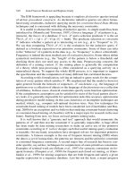
Figure
6.6
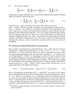
The viscosity
of
various water-based mixtures
I
.o
B
6
4
3
2
io-'
B
6
4
3
2
1Ci2
For
all practical purposes the above fluids may be classed as Newtonian but other fluids, such as water-in-oil emulsions, are
non-Newtonian. The viscosity values given for the typical
40%
water-in-oil emulsion are for very low shear rates.
For
this
emulsion the viscosity will decrease by
10%
at shear rates
of
about
3000s-'
and by
20%
at shear rates
of
about
10
000s-'.
C6.6
Plain bearing lubrication
e7
Mineral
oils
and greases
are
the
most suitable lubricants
for
plain bearings
in
most applications. Synthetic
oils
may be
required ifsystem temperatures
are
very high. Water and process fluids can
also
be
used
as
lubricants
in
certain applications.
The general characteristics
of
these main classes
of
lubricants are summarised in Table 7.1.
Table
7.7
Choice
of
lubricant
Table
7.2
Methods
of
liquid lubricant
supply
~~
Lubricant Operating range Remarks
Mineral All conditions of Wide range of viscosities
oils
load and available. Potential
speed corrosion problems
with certain additive
oils (e.g. extreme
pressure) (see Table
7.9)
Synthetic All conditions
if
Good high and low
oils
suitable temperature properties.
viscosity Costly
available
Greases
Use
restricted to Good where sealing
operating against dirt and
speeds below moisture necessary
1
to
2
m/s and where motion is
intermittent
Process Depends
on
May be necessary to
fluids properties of avoid contamination
of
fluid food products,
chemicals, etc.
Special attention to
design and selection of
bearing materials
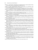
The most important property of
a
lubricant
for
plain
bearings
is
its
viscosity.
If
the viscosity is too low the bearing
will have inadequate load-carrying capacity, whilst if
the viscosity is too
high
the power
loss
and the operating
temperature will be unnecessarily high. Figure 7.1 gives
a
guide
to
the value
of
the minimum allowable viscosity
for
a
range
of
speeds and loads. It should be noted that these
values apply for a fluid at the mean bearing temperature.
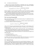
The viscosity
alf
mineral
oils
falls with increasing tempera-
ture.
The
viscosity/temperature characteristics
of
typical
mineral oils are shown in Figure 7.2.
The
most widely used
methods
of
supplying lubricating oils to plain bearings are
listed in Table 7.2
The tubricatinq properties
of
greases
are
determined to
a
large extent by the viscosity
of
the base
oil
and the type of
thickener
used
in their manufacture. The section
of
this
handbook
on
greases summarises the properties
of
the
various types.
Additive oils are not required for
plain
bearing lubrica-
tion but other requirements of the system may demand
their use. Additives and certain contaminants may create
potential corrosion problems. Tables 7.3 and 7.4 give a
guide to additive and bearing material requirements, with
examples
of
situations in which problems
can
arise.
Method
.f
Main characteristics
WblY
Exampies
__
-
Hand
Non
automatic, irregular. Low-speed,
High maintenance cost bearings
Drip and Non automatic, Journals in
oiling. Low initial cost. cheap journal
wick adjustable. some machine
feed Moderately efficient.
tools,
axles
Cheap
Ring and Automatic, reliable. Journals in
collar Efficient, fairly cheap. pumps,
feed Mainly horizontal blowers, large
bearings electric
motors
Bath and Automatic, reliable, Thrust bearings,
splash
efficient.
bath
only.
lubri-
Oil-tight housing Engines,
cation required process
general
High initial cost machinery,
Pressure Automatic. High-speed and
feed Positive and adjustable. heavily
Reliable and efficient. loaded
High initial cost journal and
thrust
bearings in
machine
tools,
engines
and
compressors
Notes
Pressure oil feed
:
This is usually necessary when the heat
dissipation of the bearing housing and
its
surroundings is
not sufficient to restrict its temperature rise
to
20°C
or
less
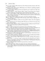
grooves in the bearing housing. Some common arrangements
are shown in Figure
7.3
pressure feed from the centre of the bearing
satisfactory performance and long life
Journal bearings: Oil must be introduced by means of oil
Thrust bearings: These must be lubricated by oil bath
or
by
Cleanliness: Cleanliness of the oil supply is essential for
C7.1
c7
Plain bearing lubrication
Table
7.3
Principal additives and
contaminants
Problem
Occurs
in
Requirements
Oxidation of
IC
engines Antioxidant
lubricant Steam turbines additives
Compressors
High-speed
gearboxes
Scuffiing Gearboxes Extreme-
Cam pressure
mechanisms additive
Deposit formation IC engines Dispersant
Compressors additives
Excessive wear General
of lubricated
surfaces
Antiwear
additives
Water IC engines Good
contamination Steam turbines demulsification
Compressors properties.
Turbine-
quality oils
may be
required
Dirt particle
IC
engines Dispersant
contamination Industrial plant additives
Weak organic IC engines Acid neutraliser
acid
contamination
Strong mineral Diesel engines Acid neutraliser
acid Process fluids
contamination
Rusting IC engines Rust inhibitor
Turbines
Industrial plant
General
Plain journal bearings
Surface speed,
Mean pressure,
where
u
=
ndn,
ms-'
7
=
-,
kNm-*
n
=
shaft speed,
s-'
I
=
bearing width, m
d
=shaft diameter,
m
W
Id
W
=
load,
kN
Minimum allowable viscosity
qmin.,
cP,
may be read directly
Plain thrust bearings
Surface speed,
u
=
nDn,
ms-'
Mean pressure
7
=
KW,
kNrn-'
ID
where
n
=
shaft speed,
s-'
I
=
width
of
bearing ring, m
D
=
mean pad diameter, m
W
=
thrust load,
kN
(3
Minimum allowable viscosity
qrhrust
=
qmin,
Surface speed,
ft/min
100
1000
000
1
00
10
11
0.1
1
.o
10.0
3'
Surface speed,
mls
1
.o
1.01
1.001
3
Figure
7.1
Lubricant wiscosity for plain bearings
C7.2
Plain bearing lubrication
e7
Table
7.4
Resistance to corrosion of bearing metals
Maximum Additive
or
contaminant
Strong mineral Synthetic
acids
oil
Lrnperature, Extreme-pressure
Weak
organic
“C
additive Antioxidant
acidc
Lead-base white metal 130 Good Good Moderatelpoor
Fair Good
Tin-base whi1:e metal
130 Good Good Excellent Very good Good
Copper-lead (without overlay) 170 Good
Good Poor Fair Good
Lead-bronze (without overlay)
180 Good with good
Good Poor
Moderate Good
quality bronze
Aluminium-tin alloy
170
Good Good Good Fair Good
Silver 180 Sulphur-contain- Good Good-except Moderate Good
ing additives tor sulphur
must not be
used
Phosp hor-bronze
220
Depends on Good Fair Fair Good
quality of
bronze.
Sulphur-
ised additives
can intensifv
corrosion
Copper-lead
or
lead-bronze
170
Good Good Good Moderate Good
with suitable overlay
Note:
corrosion
of
bearing metals
is
a complex subject.
The
above offers a general guide. Special care is required with extreme-pressure
lubricants; if in doubt refer to bearing
or
lubricants supplier.
10 000
5000
3000
2000
1000
500
300
-
200
i
‘;i
100
5!
.o
50
E
0
0
4-
._
>
5
30
20
10
7
5
41-
-1
0
Temperature,
‘C
Figure
7.2
Typical viscosity,’temperature
characteristics
of
mineral
oik
Bearing temp era ture
Lubricant
supply
rate
should
be
sufficient to restrict the
temperature rise through
the
bearing
to
less
than
20°C.
A
working estimate
of
the
mean
bearing temperature,
is
given
by
ebenring
=
6svpply
+
20,
“c
Dynamic and Kinematic Viscosity
Dynamic Viscosity,
q
(cP)
=
Density
X
Kinematic Viscosity
(cst)
Viscosity classification grades are usually expressed in
terms
of
Kinematic Viscosities.
c7.3
c7
PI
a
i
n
bea
ri
ng
I
u
b
ri
cat
i
on
Rotation
Unidirectional
Reversible
Housing
Unit
Split
Fixed Variable
Unitlsplit
I
Direction
of
load
AXIAL*
W
GROOVE
@
W
AXIAL*
GROOVES
w
CIRCUMFERENTIAL GROOVE
CIRCUMFERENTIAL GROOVE
*
At moderate speeds oil holes may be substituted if
l/d
does not exceed 1.
Note:
the load-carrying capacity
of
bearings with circumferential grooves is somewhat lower than with axial grooves
owing
to
the
effect
of
the groove
on
pressure generation.
Figure
7.3
Oil grooves in journal bearings
c7.4
~~
Rolling bearing lubrication
C8
SELECTION
OF
THE
LUBRICANT
Table
8.7
General guide for choosing between grease and oil lubrication
Factor
affecting
the
choice
1Jse
grease
Use
oil
Temperature
Up to 120°C-with special greases
or
short
Up to bulk oil temperature of 90°C
OF
bearing
temperature of 200°C-these temperatures may
be exceeded with special oils
relubrication intervals up to 20O/22O0C
Speed factor.
IJp to
dn
factors of
300
000/350
000
(depending
Up to
dn
factors of
450 000/500
000
(drpending
on
type of bearing) on design)
Load Low to moderate All loads up to maximum
Bearing design
Not for asymmetrical spherical roller thrust All types
bearings
Housing design Relatively simple
Long periods without
Yes, depends on operating conditions, especially
No
More complex seals and feeding devices necessary
attention temperature
Central oil supply for No-cannot transfer heat efficiently
or
operate Yes
other machine elements hydraulic systems
Lowest torque When properly packed can be lower than oil on
For
lowest torques use a circulating system with
which the grease is based scavenge pumps
or
oil mist
Dirty conditiom
~
Yes-proper design prevents entry
of
con- Yes, if circulating system with filtration
taminants
*
dn
factor (bearing bore (mni)
x
speed (revimin)).
Note:
for large bearings
(>
65
mm bore) use
nd,
(d,
is
the arithmetic mean of outer diameter and bore (mm)
)
G
R
EASE
LUI
B RICATION
Grease sellection
The principle factors governing the selection of greases
for rolling bearings are speed, temperature, load, environ-
ment and method of application. Guides to
the
selection
of a suitable grease taking account
of
the
above
factors are
given in Tables 8.2 and 8.3.
The appropriate maximum speeds
for
grease lubrication
of a given bearing type are given in Figure 8.1. The life
required from the grease
is
also obviously important and
Figure 8.2 gives a guide to the variation of grease
operating life with percentage speed rating and tempera-
ture
for
a high-quality lithium hydroxystearate grease as
derived
from
]Figure
8.1.
(These
greases give the highest
speed ratings.)
When shock loading and/or high operating temperatures
tend
to shake the grease out
of
the covers into the bearing,
a grease of a harder consistency should be chosen, e.g. a
no.
3
grease
instead
of
a
no.
2
grease.
Note:
it
should
be
recognised that the curves in Figures 8.1 and
8.2
can only
be
a guide. Considerable variations
in
life are possible
depending on precise details
of
the application, e.g. vibration, air
flow
across the bcearing, clearances, etc.
Table
8.2
The effect of the method of appli-
cation on the choice of
a
suitable grade
of grease
System
NLGI
grade
no.
Air
pressure
0
to
2
depending on type
up
to
3
Pressure-guns
or
mechanical
lubricators
Compression cups up to
5
Centralised lubrication
2
or
below
(a)
Systems with separate metering
Normally
1
or
2
valves
(b)
Spring return systems
I
(c)
Systems with multi-delivery
3
pumps
C8.1
C8
Rolling bearing lubrication
Table
8.3
The effect
of
environmental conditions
on
the choice
of
a suitable type
of
grease
Sbeed maximum Tvbical service temberatur~
/A
NLGI
hercentage
no. maximum
for
ljpe
of
grease grade recommended Environment Maximum Minimum
Base
Oil
uiscosi~
Comments
(approximate values)
grease)
"C
OF
"C
"F
Lithium
Lithium
2
{
:P
Multi-purpose, not advised
at max. speeds or max.
temperatures
for
bearings
above 65 mm bore or on
up
to 140 cSt at
100°F vertical shafts
For
max. speeds recom-
mended where vibration
loads occur at high speeds
Lithium EP
1
75 Wetordry 90 195 -15 5 Recommended
for
roll-neck
70 160)
-
15
}
14.5 cSt at 210°F bearingsand heavily-load-
Wetordry
9o
195 ed taper-roller bearings
Lithium EP
2
Calcium 1,2and3 50 Wetordry
60
140 -10 14 140cSt at 100°F
(conventional)
~~
Calcium EP
1
and
2
50 Wetordry
60
140 -5 25 14.5 cSt at 210°F
Sodium
3
75/100 Dry
80
175 -30 -22 30cSt at 100°F Sometimes contains
20%
(conventional) calcium
Clay 50 Wetordry 200 390
10
50 550 cSt at 100°F
Clay
100
Wetordry 135 275 -30 -22 Up to 140 cSt at
100°F
Clay
100 Wet or dry 120
248
-55 -67 12 cSt at 100°F Based on synthetic esters
Silicone/lithiurn
75
Wet
or
dry 200
390
-40 -40 150 cSt at 25°C Not advised for conditions
where sliding occurs at
high speed and load
200
10
000
8000
S
6000
5
Li
4000
0-
L
50
3000
LrY
2500
%
5
LL
1500
a
*
w
20
c
$
100
5000
f
w
0
2000
4
6
m
1000
I
0
20
40
60
80
100
120
140
BEARING
BORE,
rnrn
Figure
8.1
Approximate maximum speeds for
grease lubrication. (Basic diagram for calculating
bearing speed ratings)
.Vultipl_v bearing
speed
from
Figure
8.1
bv
this,
factor
to
get
/he
maximum
speed
for
each
Qpe
of
bearing
Bearing
gpe
-
Cage centred on
As
Figure
8.1
3
Pressed cages 1.5-1.75
x
centred
on
-0
rolling elements
E
&
Machined cages 1.75-2.0
2.;
centred on
'i:
m
5
5
Machined cages 1.25-2.0
2
centredon
outer race
m
inner race
.z
.e
rolling elements
Taper- and spherical- roller 0.5
bearings
Bearings mounted
in
0.75
adjacent pairs
Bearings
on
vertical shafts 0.75
Bearings with rotating outer 0.5
races and fixed inner
races
C8.2
Rolling bearing lubrication
roo
000
50
ooal
z
W-
20000
Lb
d
g
10000
:
2
a
8
5000
W
r
a
::
2000
OI
1300
1000
500
C8
Method
of
lubrication
Rolling bearings may be lubricated with grease by a
lubrication system as described in other sections of the
handbook or may be packed with grease on assembly.
Packing ball and roller bearings with grease
(a)
The grease should not occupy more than one-half
to three-quarters of the total available free space in the
covers with the bearing packed
full.
(b)
One
or
more bearings mounted horizontally-com-
pletely fill bearings and space between, if more than one,
but fill only two-thirds to three-quarters of space in covers.
(c)
Vertically-mounted bearings-completely fill bear-
ing but fill only half of top cover and three-quarters of
20
40
60
80
100
120
140
TEMPERATURE,
'C
bottom cover.
Figure
8.2
\/ariation
of
operating life
of
a high-
quality grade
3
/ithiurn hydroxystearate grease with
speed
and temperature
(d)
Low/medium speed bearings
in
dirty environments
-comP1etely bearing
and
covers.
Calculation
of
relubrication interval
The relubrication period for ball and roller bearings may
be estimated using Figures
8.1
and
8.2.
The following is
an
example in terms of
a
typical application:
Required
to
know
:
Approximate relubrication period
for the following:
Bearing type
:
Medium series bearing 60 mm bore.
Cage
:
Pressed cage centred on balls.
Speed
:
950
rev/nnin.
Temperature
:
120°C [The bearing temperature
(not merely the local ambient tem-
perature) i.e. either measured
or
estimated
as
closely
as
possible.]
Position
:
Vertical shaft.
Grease
:
Lithium grade
3,
Duty
:
Continuous.
From Figure
8.1
:
60 mm bore position on the lower
edge of the graph intersects the
medium series curve at approxi-
mately
3100
revlmin.
Factor for pressed cages on balls
is
about
1.5;
thus
3100
x
1.5
=
4650 revlmin.
Factor for vertical mounting
is
0.75. Thus 4650~0.75
=
3488 sev/min.
This
is
the rnaximum speed rating
(
100%).
Now actual speed
=
950
rev/min; therefore percentage
-
9
50
348%
of maximum
=
-x
100
=
27% (say 25% approxi-
mately).
In
Figure
8.2
the
12D"C
vertical line intersects the
25%
speed rating curve for the grade
3
lithium grease at
approximately
1300
hours, which
is
the required answer.
Relubrication
of
ball
and
roller bearings
Relubrication may be carried out in two ways, depending
on the circumstances
:
(a)
Replenishment, by which
is
meant the addition
of
fresh grease to the original charge.
(b)
Repacking, which normally signifies that the bearing
is dismounted and all grease removed and discarded, the
bearing then being cleaned and refilled with fresh grease.
An alternative, if design permits,
is
to
flush the bearing
with fresh grease
in
situ.
(Grease relief valves have been
developed for this purpose.)
The quantity required per shot is an arbitrary amount.
Requirement is only that sufficient grease
is
injected
to
disturb the charge in the bearing and
to
displace same
through the seals, or grease relief valves.
A guide can be obtained from
Dxw
W=-
200
where
W
is quantity
(g)
and
w
is
width (mm)
D
is outside diameter (rnm)
If
grease relief valves are
not
fitted, the replenishment
charge should not exceed 5% of the original charge. After
grease has been added to a bearing, the housing vent plug
(if fitted) should be left out for a few minutes after start-up
in order to allow excess grease to escape. A better method,
if conditions allow, is
to
push some
of
the static grease in the
cover back into the bearing
to
redistribute the grease
throughout the assembly. This method
is
likely to be
unsatisfactory when operating temperatures exceed about
100°C.
C8.3
C8
cst
450
260
170
100
90
80
70
60
50
40
30
20
10
9-
8-
6-
c
OIL
LUBRICATION
Oil viscosity selection
-
-
-
-
-
-
-
-
-
-
-
-
-
-
-
-
1
-
-
-
-
-
-
-
-
-
7-
Rol
I
i
ng bearing
I
ubrication
50.0
30.0
20.0
13.0
10.0
9.0
8.0
7.0
Generally, when speeds are moderate, the following
minimum viscosities at the operating temperatures are
recommended
:
cSt
Ball and cylindrical-roller bearings 12
Spherical-roller thrust bearings
32
The oils will generally be
HVI
or
MVI
types containing
rust and oxidation inhibitors. Oils containing extreme
pressure
(EP)
additives are normally only necessary for
bearings where there is appreciable sliding, e.g. taper-
roller or spherical-roller bearings, operating under heavy
or
shock loads, or if required for associated components,
e.g. gears. The nomogram, Figure
8.3,
shows
how
to
select
more precisely the viscosity needed for known bore and
speed when the operating temperatures can be estimated.
If the operating temperature is not known or cannot be
estimated then the manufacturer's advice should be sought.
Spherical-roller bearings
20
-
-
-
-
:
:
:
:
R"
1500
1000
800
600
400
300
200
150
100
90
80
70
60
50
45
40
2.5
2.0
1.8
1.6
1.5
1.4
VISCOSITY
-
:
-
:
:
7
SI'
2000
1000
80
0
600
500
400
300
200
150
100
90
80
70
60
50
45
To
use Figure
8.3,
starting with the right-hand portion
of
the graph
for
the appropriate bearing bore and speed,
determine the viscosity required for the oil at the working
temperature. The point of intersection of the horizontal
line, which represents this oil viscosity, and the vertical line
from the working temperature shows the grade of oil to be
selected.
If
the point of intersection lies between
two
oils,
the thicker oil should be chosen.
Examples:
Bearing bore
d
=
60
mm, speed
n
=
5000
rev/
min (viscosity at working temperature
=
6.8
cSt), with working temperature
=
65°C.
Select
oil
S
14
(14
cSt at
50°C
approx.)
Bearing bore
d
=
340
mm, speed
n
=
500
rev/
min (viscosity at working temperature
=
13.2
cSt), with working temperature
=
80°C.
Select
oil
S
38
(38
cSt
at
50°C
approx.)
100
130 210°F
150 250400
d,
mrn
20
30
40
50
60
70
BO
90
100
110 12OoC
50
75100 200300
500
d.mm
R"=
Redwood
No.
1
seconds;
S"
=
Saybolt
Universal seconds,
SSU
E"
=
degrees Engler
CSt
=
centistokes
Figure
8.3
Graph for the selection of
oil
for roller bearings
(permission of the
Skefko
Ball
Bearing
Co.
Ltd).
The
graph has been compiled for a viscosity index of
85,
which represents
a
mean value of the variation
of
the viscosity of
the lubricating oil with temperature. Differences for
95
VI
oils are negligible
C8.4
Rolling
bearing
lubrication
Application
of
oil
to
rolling bearings
C8
System
Conditions
Oil
levelsloil
flow
rates
Comments
Bath/splash
Generally used where speeds are low Bearings
on
horizontal and vertical
A
limit in
dn
value
of
ooo
is
some-
shafts, immerse half lowest rolling
element
times quoted, but higher values can
be accommodated if churning is not Multi-row bearings on vertical shafts,
a problem fully immerse bottom row of
elements
Oil flingers, drip feed Normally as for bath/splash Flow rate dictated by particular Allows
use
of
lower oil
lubricators, etc. application; ensure flow is sufficient level if temperature-
rise is too high with to allow operation of bearing below
desired
or
recommended
maximum
bath/splash
temperature
-
generally between
70°C
and
90°C
Pressure circulating
No
real limit to
dn
value
Use
oil
mist where speeds are very high
As
a guide, use:*
0.6
cm3/min cmz of The oil flow rate has
projected area of bearing generally to be de-
(0.d.
x
width) cided by considera-
tion
of the operating
temperature
Oil
mist
No
real limit to
dn
value
Almost
invariably used
for
small bore
bearings above
50
000
revlmin, but
also
used at lower speeds
As a guide, use:*
0.1
to
0.3
x
bearing
bore (cm/2.54)
x
no. of rows-cm3/
hour
Larger amounts are required for pre-
loaded units, up to
0.6
x
bearing
bore (cm/2.54)
x
no. of rows-cm3/
hour
In some cases oil-mist
lubrication may be
combined with an
oil bath, the latter
acting as a reserve
supply which is par-
ticularly valuable
when high-speed
bearings start to run
*
It
must
be
emphasised that values obtained will be very approximate and that the manufacturer's advice should be sought
on
the
performancc of equipment of
a
particular type.
C8.5
Gear and roller chain lubrication
Pitch
line
speed, ft/min
10
50
100
500
1000
2500 5000
10
000
0
1000
a0
0
m-
500
U
i3
m,
"0
0
m
CO
d
d
100
P)
0
i
K?
x
50
8
P
>
0
v
+
101
'
I
Ii
I I I'
I
lJ
0.1
0.25 0.5
1.0
2.5 5
10
25 50
Pitch line speed,
m/s
Figure
9.
I
Selection of oil for industrial enclosed
gear units
Figure
9.1
is
a
general guide only. It is based on the
criterion:
Sc
HV/(Vp
+
100)
where
Sc
=
Surface stress factor
Load/inch line of contact
Relative radius of curvature
HV
=
Vickers hardness for the softer member of the
- -
and
gear pair
Vp
=
Pitch line velocity, ft/min
The chart applies to gears operating in an ambient tem-
perature between 10°C and
25°C.
Below
10°C
use one grade
lower. Above
25°C
use one grade higher. Special oils are
required
for
very low and very high temperatures and the
manufacturer should be consulted.
With shock loads,
or
highly-loaded low-speed gears,
or
gears with a variable speed/load duty cycle,
EP
oils may
be used. Mild
EPs
such as lead naphthanate should not be
used above
80"C(
170°F)
running temperature. Full hypoid
EP
oils may attack non ferrous metals. Best
EP
for normal
industrial purposes is low percentage of good quality
sulphur/phosphorus
or
other carefully inhibited additive.
Spray
lubrication
Quantity
Speedmjsec
10
25
50
100
150
10
100
140
180
210
85
x
10
-'
x
kW
Pressure
m3/sec kN/m2
Quantity
Speedftlmin
2500 5000
10000
20000 30000
0.0085~
hp
Pressure
1o
15
2o
25
3o
BPm
Ibf/in2
Pitch line speed, ft/min
10
50
100
500
10002000
5000
10
000
1000
0
%
500
d
li-
i3
"0
0)
e
m
=:
100
m
's
i
50
8
::
E
8
c
5.
lo
0.1
0.25 0.5
1.0
2.5 5
10
25
50
Pitch line speed,
m/s
Figure
9.2
Selection of oil for industrial enclosed
worm gears
Suitable lubricants for worm gears are plain mineral oils
of
a
viscosity indicated in Figure
9.2.
It is also common
practice, but usually unnecessary,
to
use fatty additive or
leaded oils.
Such
oils may be useful
for
heavily-loaded,
slow-running gears but must not be used above
80°C(
170°F) running temperature as rapid oxidation may
occur, resulting in acidic products which will attack the
bronze wheel and copper
or
brass bearing-cages.
Worm gears do not usually exceed a pitch line velocity
of
2000
ft/min, but if they do, spray lubrication is essential.
The sprayed oil must span the face width of the worm.
Quantity
Speed
m/s
10
15
20 25
75x10dxC*
Pressure
kN/m2
100
170
270
340
m3/sec
C*
=
centre distance in metres.
Quantity
Speedftlmin
2000
3000
4000
5000
Q=
C/4
gpm
Pressure
lbf/in2
15
25
40
50
Where
C
=
centre distance, inches.
Recent developments in heavily loaded
worm
gear
lubrica-
tion include synthetic fluids which:
(a)
have a wider operating temperature range
(b)
reduce tooth friction losses
(6)
have a higher viscosity index and thus maintain an oil
film at higher temperatures than mineral oils
(d)
have a greatly enhanced thermal and oxidation
stability, hence the life is longer
Even mcire recent developments include the formulation
of
certain soft synthetic greases which are used in 'lubri-
cated-for-life' worm units. Synthetic lubricants must not
be mixed with other lubricants.
c9.1
Gear
and
roller chain lubrication
C9
AUTOMOTIVE
LUBRICANTS
SAE
classification of transmission and
axle lubricants
Centistokes
Redwood
seconds
SAE
sip
0°F
-
18°C
2
10°F 99'C
0°F
-
18°C
2
10°F
99°C
Min. Max. Min. Max.
Min.
Max. Min Max.
75
-
3250
-
- -
13100
- -
80
3250*
21
700
- -
13100
87600
-
-
90
-
14
25
- -
66
107
140
-
-
25
43
-
-
107
179
179
-
-
250
41
-
-
NO~:
*
The
min. viscosity
at
0°F
may
be
waived if
the
viscosity
is
not
less than
7
cSt
at
210°F.
These values are approximate and are given for information only.
Selection
of
lubricants for
transmissions and axles
Almost
invariably dip-splash.
The modern tendency
is
towards
universal
multipurpose
oil.
Rear axles
Manual
Automatic
Rear axles (spiral
gear boxes
gear boxes
(hypoidr) bevel and
worn)
Cars
SAE;80 (EP)
or multi-
purpose
Heavy SAE,
80 EP
vehicles or SAE
90
(EP)
or
multi-
purpose
Automatic Highly
transrnis- active
sjon fluid
SAE 90
EP
or
multi-
purpose
(ATF)
SAE80EP
-
for semi-
auto-
matics
ATF fluid
for autos
SAE
140
or
multi-
pur-
pose
Above only
to
be used where supplier's recommenda-
tions are not available.
Above are suitable for normal conditions. In cold
conditions
(<
0°C) use one SAE grade less.
In
hot
conditions
(>
40°C)
use one
SAE
grade higher.
In
most cases (except hypoids), straight oils are accept-
able. The above
EPs
are given for safety if supplier's
recommendations are not known.
Some synthetic (polyglycol) oils are very successful with
worm gears. They must not be mixed with any other
oils. ATF fluids must
not
be mixed with others.
Change periods: (only if manufacturer's recommenda-
tions
not lmown). Rear axles-do not change. Top up
as
required.
All
manual and automatic gearboxes-
change after
20000
miles. Before that top up
as
required.
ROLLER CHAINS
Type
of
lubricant: Viscosity grade no.
150
(IS0
3448).
For
slow-moving chains on heavy equipment, bituminous
viscous lubricant
or
grease can be used. Conditions
of
operation determine method
of
application and topping-
up
or
change periods. Refer to manufacturer
for
guidance
under unusual conditions.
Speed
m/s(ft/min)
Method
Of
limitation Quanti9 Comments
application
1.5~ ROLLER
PITCH
Dip
<
10
-
(
<
2000)
IL
VEL
APPLIED
TO
@
Slow
drip 0-3
5-10
drops/
(0-600)
min.
Fast drip
3-75
>
20
IN-GOING
SIDE
(600-1500)
OF
CHAIN
Spray
>
7.5
Depends
(>
1500)
upon speed
P
and other
DRIVEN
ATELY
OR
conditions
FROM
CHAIN
SPROCKET
OPEN
GEARS
Applies
to
large, slow-running
gears
without oil-tight
housings.
Methods
of
Requirements
of
Type.r
of
lubricant
application
lubricant
Must form protective Generally bituminous
film and tacky.
Sometimes cut back
by volatile diluent
heavy
EP
oils
Must not be squeezed
out Can use grease or
Must not be thrown
Off
Hand, brush,
paddle
Dip-shallow
Drip-automatic
Spray-
continuous
or
intermittent
P"'
~
Must be suitable for
prevailing ambient
conditions
Viscosity
ofopen
gear lubricant
CS
at
38"C(
1OO"fl
7emperature
sprclv
Drip
"C
Residual
Mild
EP
oil
comPOund
Mild
EP
oil
200-650
-
-10
to
15
-
1w120
18CL200
65C2000
65&2000
5
to
35
100-120
25
to
50 18CL2QQ
C9.2
CIO
Slide
lubrication
Slides
are
used where
a
linear
motion
is
required between
two components.
An
inherent feature
of
this linear motion
is
that parts of the working surfaces must
be
exposed during
operation. The
selection
of
methods
of
slide lubrication
must
therefore
consider
not
only
the
supply
and
retention
of
lubricant, but also
the
protection
of
the working surfaces
from
dirt contamination.
EXPOSED SURFACE
/, 7
EXPOSED
SURFACE
\
EXWSED SURFACE
Figure 10.1 Slide movements exposes the working
surfaces to contamination
Table
10.
1
The
lubricafion
of
slides in various
applications
Application
Function
of
lubricant Lubricant commonly used Remarks
Slides and linear bearings on To minimise the wear of precision Depends on the type of slide
or
Swarfmust be prevented from
machine tools surfaces. Toavoid any tendency linear bearing. See next Table getting between the sliding
to stick slip motion surfaces
Slides and linear bearings
on
To
reduce friction and wear at the Greases and solid lubricants are The sliding contact area
should be protected from
dirt by fitting scraper seals
packaging machines, textile
machines, mechanical
handling devices handled at each end if possible
moving surfaces without con-
taminating the material being
commonly used but air lubri-
cation may also be possible
Crossheads on reciprocating To give low friction and wear by The same oil as that used for the Oil grooves
on
the
stationary
engines and compressors maintaining an adequate film bearings surface are desirable to help
to provide a full oil film to
thickness to carry the impact
loads carry the peak load
01
L
LEVEL
01
L
OIL
LEVEL LEVEL
Figure
10.2
Typical wick lubricator arrangement
on a machine tool
Figure
10.3
Typical roller lubricator arrangement
on
a
machine tool
Table
10.2
The
lubrication
of
various types
of
linear bearings
on
machine tools
Type
of
linear bearing Suitable lubricant Method
of
applying
the
lubricant Remark5
Plain slide ways Cutting oil By splash from cutting area
Only suitable in machine tool applications
using oil
as
a cutting fluid
Mineral oil
By wick feed to grooves in the shorter
Requires scraper seals at the ends of the
containing polar component moving component
to
exclude swarf
additives to reduce
boundary friction
By rollers in contact with the bottom
face ofthe upper slide member, and
contained in oil filled pockets
in
the
lower member
Only suitable for horizontal slides
Requires scraper seals
at
the ends of the moving
component to exclude swarf
By oil mist
Air exhaust keeps the working surfaces
clear
of swarf
Grease
By grease gun
or
cup, to grooves in Particularly suitable for vertical slides, with
thesurfaceoftheshortercomponent
occasional slow movement
Hydro-static plain Air
or
any other con- Under high pressure via control Gives very low friction and no stick slip
slideways veniently available valves to shallow pockets in the combined with high location stiffness.
surface
of
the shorter member fluid
Keeps working surfaces clear of swarf
Linear roller bearings Oil
Lower race surface should be just Not possible in all configurations. Must be
covered in an oil bath
protected from contamination
Grease Packed on assembly but with grease
Must
be protected from contamination
nipples for replenishment
c10.1
Lubrication of flexible couplings
c11
FILLED COUPLINGS (GEAR, SPRING-TYPE, CHAIN)
ble
f
1.
1
Recommendations for the lubrication of filled couplings
Limiting criteria
Centn fuga1 Effects
Lubricant Lubricant
OPe Pitch-line Range
in
Heat change
acceleration practical Dissipation period
dm2/2
units
(I?l/SK?)
Dn2
@/sec2)
Pn
Remark3
No
1
Grease
0.15
x
1oI3
25 max
-
(mineral
0.5
x
io3
25-80
-
No
3
Grease
1.5
x
io3
80-250
-
(mineral
5.0
x
io3
250-850
-
oil
base)
12.5
x
io3
85CL2000
-
oil
base)
2 years
12 months
9
months
6
months
3
months
Soft grease preferred
to
ensure penetration
of lubricant
to
gear teeth
Limitation
is
loss
of
oil
causing hardening
of
grease;
No
3
grease
is
more mechanically stable
than
No
1.
Semi-
fluid
polygly
col
45.0
x
io3
300&5000
230
x
io3
2 years
grease
or
max
mineral
oil
Sealing
of
lubricant in
coupling is main problem
d
=
pcd,
m;
D
=
pcd,
ft;
w
=
rads/sec;
n
=
revisec;
P
=
hp
transmitted
Limits
Grease lubrication, set
by
soap separation under centrifug-
ing action. Semi-fluid grease lubrication, set
by
heat
dissipation.
Gear Coupling
Spring Coupling
Chain Coupling
'ROLLER
CHAIN
Y tt t
Figure
11.
I
Types
of filled couplings
c11.1
c11
Lubrication
of
flexible coudinrrs
CONTINUOUSLY-LUBRICATED GEAR
COUPLINGS
Lubrication depends
on
coupling type
Figure 11.3 Dam-type coupling with anti-sludge
holes
Limits:
set
by centrifuging of solids
or
sludge in oil causing
coupling lock:
damless-type couplings
dam-type couplings
45
X
lo3
m/sec2
30
X
lo3
m/sec2
Lubricant
feed
rate:
damless-type couplings
dam-type coupling with
sludge holes
dam-type coupling without
sludge holes
Rate given on Figure
11.5
50%
of rate
on
Figures
11.5
25%
of
rate
on
Figures
11.5
Figure 11.4 Damless-type coupling
Oil
-
d
a a
Figure 11.2 Dam-type coupling
0
t
Anti-sludge hole
Oil
supply
-
@
0.4
0.3
E
d
z
0.2
0.1
4000
5000
6000
7000
8000
Speed, rpm
Figure 11.5 Lubrication requirements
of
gear coup-
lings
Lubricant:
Use
oil
from
machine
lubrication
system
(VG32,
VG46
or
VG68)
c11.2
Wire rope lubrication
c12
THE
ADVANTAGES OF
LUBRICATION
Increased fatigue
life
Correct lubricants will facilitate individual wire adjust-
ment to equalise stress distribution under bending con-
ditions.
An
improvement of up to
300%
can
be
expected
from a correctly lubricated rope compared with
a
similar
unlubricated rope.
RANGE
OF
EXPECTED
IMPROVEMENT
P
c
"
PETROLATUM SOFT
SEMI- HARD
TYPES
BITUMINOUS BITUMINOUS
TYPES TYPES
TYPE
OF
LUBRICANT
Figure 12.1 Percentage increases in fatigue life
of
lubricated rope over unlubricated rope
Increased corrosion resistance
Figure 12.2 Typical effect of severe internal corro-
sion. Moisture has caused the breakdown of the fibre
core and then attacked the wires at the atrandcore
interface
Figure 12.3 Typical severe corrosion pitting as-
sociated with 'wash off'
of
lubricant by mine water
Increased abrasion resistance
Figure 12.4 Typical abrasion condition which can be
limited by the correct service dressing
LU
B
R
lCATl0
N
D
U
RING
MANUFACTURE
The
Main
Core
Fibre cores should be given a suitable
dressing during their manufacture.
This
is more effective
than subsequent immersion of the completed core in heated
grease.
Independent wire rope cores are lubricated in a similar
way to the strands.
The
Strands
The helical form taken by the individual
wires results in
a
series of spiral tubes in the finished strand.
These tubes must
be
filled with lubricant if the product is
to resist corrosive attack. The lubricant is always applied
at the spinning point during the stranding operation.
The
Rope
A
number of strands, from three to fifty,
will
form the final
rope
construction, again resulting in voids
which must be filled with lubricant. The lubricant may be
applied during manufacture at
the
point where the strands
are closed to form the rope,
or
subsequently by immersion
through a bath if
a
heavy surface thickness
is
required.
Dependent on the application the rope will perform, the
lubricant chosen for the stranding and closing process
will
be either
a
petrolatum
or
bituminous based compound.
For certain applications the manufacturer may use special
techniques for applying the lubricant.
Irrespective of the lubrication camed out during rope
manufacture, increased rope performance
is
closely
asso-
ciated with adequate and correct lubrication of the ropr
in service.
(32.1
c12
Wire
rope
lubrication
LUBRICATION
OF
WIRE
ROPES
IN
SERVICE
(1)
(2)
(3)
(4)
(5)
Operating
Ropes working in Ropes subject to Ropes working As
(3)
but for Standing ropes
conditions
industrial
or
heavy wear
over sheaves friction drive not subject
to
marine where (1) and applications bending
environments
(2)
are not
critical
Predominant
Corrosion Abrasion Fatigue Fatigue-corrosion Corrosion
Cause
of
rope
deterioration
Typical
Cranes and derricks
Mine haulage,
Cranes and grabs,
Lift suspension, Pendant ropes for
applications
working on
excavator jib suspension
corn pema ting cranes and
ships, on draglines, ropes, piling, and governor excavators. Guys
docksides,
or
in scrapers and percussion and ropes, mine for masts and
polluted slushers drilling hoist ropes on chimneys
atmospheres friction winders
Dressing
Good
penetration Good antiwear Good penetration Non slip property. Good corrosion
requirements
to
rope interior. properties. Good to rope interior. Good penetration protection.
Ability to displace adhesion to rope. Good lubrication to rope interior. Resistance to
moisture. Resistance to properties. Ability to ‘wash
off
’.
Internal and removal by Resistance to displace Resistance to
external mechanical ‘fling
off’
moisture. surface cracking
corrosion forces Internal and
protection. external
Resistance to
‘wash
off
’.
protection
Resistance
eo
emulsification
corrosion
=YPf
!f
Usually
a
Usually
a
very Usually a good Usually a solvent- Usually
a
lubricant
formulation viscous oil or general purpose dispersed relatively thick,
containing soft grease lubricating oil temporary bituminous
solvent leaving containing
of
about
SAE
corrosion compound with
a thick
MoS,
or
30
viscosity preventative solvent added
(0.1
mm) soft graphite. leaving a thin, to assist
grease film Tackiness semi-hard film application
additives can
be of advantage
Application
Manual or Manual
or
Mechanical Normally by hand Normally by hand
technique
mechanical mechanical
Frequency
of
Monthly Weekly 10/20 cycles per Monthly
Six
monthly/
applications*
day
2
years
*
The periods indicated are for the general case. The frequency
of
operation, the environmental conditions and the economics of service
dressing will more correctly dictate the period required.
APPLICATION TECHNIQUES
Ideally
the
lubricant should be applied
close
to
the point
where
the
strands
of
the
rope
tend
to
open
when passing
/
/’
//
,/
/
over
a
sheave
or
drum.
The
lubricant may be applied manually
or
mechanically.
IJ
n
7I
It
Figure
12.5
Opening
of
rope section during passage
over sheave or drum. Arrows
indicate the access
points for lubricant
c12.2
Wire
rope
lubrication
Manual
-
By
can
or
by
aerosol
Figure 1.26 Manual application by can
Mechanical-By bath
or
trough.
By drip
feed.
By mechanical spray
Figure 12.7 Mechanical application by trough
U
d
c12
-FEED PIPE
n
PUMP
I
VEE BELT DRIVE
Figure 12.8 Drip lubrication
CHECK VALVE OPTIONAL
PREVENTS DRIPPING FOR
VERTICAL FEED
-ATOMISING
NOZZLE
Figure 12-9 Sheave application
by
spray using
fixed nozzle
ADJUST VERTICAL DISTANCE
FROM NOZZLE
TO
ROPE TO
COVER FULL ROPE DIAMETER
DIVIDER
WIDER SPRA
OIL
PRESSURE
Figure 12.10 Multisheave or drum application by
spray
C12.3
C13
Selection
of
lubrication
svstems
For
brevity and convenience the vast array
of
lubrication systems have been grouped under nine headings. These are each
more
fully
discussed
in
other
Sections
of
the
Handbook.
A
Total
loss
grease
B
Hand greasing
C Centralised greasing
D
Total
loss
oil
E
Wick/pad oil
F
Ring and disc oil
G General mist and splash
H Pressure mist
J
Circulating oil
TYPES
OF
LUBRICATION
SYSTEM
SYSTEMS
I-
GREASE OIL
Non
replenishable
Type A
Replenishable
I
I
Type
B
Local
hand
I
Centralised
I
1
automatic
I
hand
Type
B,
Type
c
I
Y
Total loss Self contained
P
Circulating
Type
J
I
I
I
I-/
Wick
Type
E
c
Hand
Centralised
Mist
Splash Dip
Type D
Type
D
TypeH
TypeG TypeF
Type letters refer
to
subsequent tables
C13.1
Selection
of
lubrication
systems
c13
METHODS
OF
SELECTION
Table
13.1
Oil
systems
Table 13.3 Relative merits of grease
and
oil
systems
=YP.
Characterzstics Application
Hand Oil can Simple bearings,
Type
D
Small numbers,
T
low duty,
0
T-
__~_____
A
Centralised Intermittent feed Small heat
L
Type
D
removal,
difficult access,
L
large numbers
0
_______
S
Mist Aerosol spray. Rolling bearings,
S
Tvpr
H
mechanisms
s
Splash Lubrication by Enclosed
E
Type
G
mist mechanisms,
L
gearboxes
easy access
______.______
F
__-_~
Dip
Ring
or
disc Plain bearings-
C
TypeF systems. Oil slow
or
0
circulates moderate duty
N
T
Wick Pad
or
wick feed Plain bearings,
A
Type E from low duty.
I
reservoir- Light loaded
N
total
loss
or
mechanisms
E limited
D
circulation
Circulating Oil from tank
or
Almost all
Type
J
sump fed by applications
pressure pump where cost is
to
bearings justified
or
sprays
Table 53.2 Grease systems
Characteristics Applications
____
7ype
Non
Bearings packed
replenishable
on assembly.
Type
'4
Refilling
impossible
without
stripping
Rolling bearings,
some plastic
bushings
Local
-
hand Grease nipple to
Type
B,
each beariilg
Small numbers,
easy, access,
cheap
Centralised
-
Feed pipes
hand
brought to
Type
B,
manifold
or
Pump
Centralised
-
Grease
pump
automatic
feed
to
bearing
Type
c
and sets of
bearings from
automatic
Pump
Reasonable
nu
rn
bers.
lna((wihIc
bearings
Large numbers,
important
bearings, great
distances.
Where frequent
relubrication
is required
Component
or
requirement
Removing heat
No
performance Grease
Oil
__
~___
__________
Yes. Amount
depends
on
system
Keep out dirt Yes. Forms
own
No.
But total
loss
systems can
flush
seal
-___~
.___~-
Operate in any Yes.
Check
No.
Unless
attitude design of specially
grease valves designed
Plain bearings Limited (slow Extensive
speed
or
light
load)
Rolling bearings Extensive Extensive
Sealed rolling Almost universal
No
~-
bearings
~-
Very low
No.
Except for Yes (check pour
temperatures
some special point of oil)
greases
Very high
No.
Except
for
Yes.
With
correct
temperatures some special system
greases
-
Very high speeds
No.
Except small Yes
rolling
bearings
Very
low
or
Yes Hydrodynamic
intermittent
bearings-
speeds iimi ted.
Hydrostatic
bearings- yes
Rubbing plain Yes Yes. With limited
bearings feed
Table 13.4 Selection
by
heat removal
___
._______~____________
System Effect
Total
loss
grease
or
oil
Dip
or
splash
-
Will not remove heat
Will remove heat from hot spots.
Will remove some heat from the
body of the components
-
__
Mist Will remove considerable heat
Recirculating.
Oil
__
__~~_____
May be designed to remove almost
any amount of heat
C13.2
c13
Selection
of
lubrication svstems
Table
13.5
Selection bv type of component to be lubricated
System Rolling bearings Fluid film plain bearings Rubbing plain bearings
Gears
Non-replenishable grease For general use Very light duty General Light duty or slow
Type A speeds
Hand grease feed Heavier loads. Slow speed General for high loads Rarely
Type
B
Higher temperatures and temperatures
Centralised grease feed Heaviest loads. Slow speed. General for high loads Slow, heavy duty
Type
c
Higher temperatures. Higher temperatures and temperatures
Large sizes
Yes Open gears
Total loss oil Most applications All where small heat
Type
D
removal
Type E
Type
F
Type G
Wick/Pad, oil Limited (light duty) Slow speed Some Small gears
Ring or disc, oil NA Medium duty NA NA
General mist and splash Most Light duty Light duty Wide
Pressure mist Tvpe
H
Almost all. Excellent Rare NA Rare
Circulating oil Type
J
All All NA All
Table
13.6
Selection by economic considerations
Notes
Lubrication Initial Maintenance Subsequent
Su
bseguent
lubricant costs labour costs
Firstfill
system purchase of system
Non- Very cheap Nil Cheap Nil
replenishable
grease
Type A
Nil
Life of bearing is life of
lubricant. Expensive if
relubricated
Grease feed Cheap Cheap Cheap Moderate Expensive Regular attendance is vital.
hand moderate but can be Neglect can be very
Type
B
if long expensive expensive
liner
Grease feed Moderate to Moderate Moderate to Moderate Moderate Needs comparatively
automatic expensive expensive skilled labour. Costs
Type
c
increase with
complications
~
Total loss oil Cheap Cheap Cheap Moderate Moderate Periodic refilling required.
Type
D
but can be Neglect can be very
expensive expensive
Wick or pad Cheap Cheap Cheap Cheap Cheap Also need topping-up but
Type
E
not
so
often and wick
gives some insurance
Ring or disc Cheap Nil to cheap Cheap Cheap Cheap Needs very little attention
Type
F
__
General splash Cheap Nil Moderate Cheap to Moderate Oil level must be watched
Type
G
moderate
Pressure mist Moderate to Expensive Cheap Cheap Moderate to Needs comparatively skilled
Type
H
expensive expensive labour. Requires
compressed air supply
~
Circulating Expensive Expensive Moderate to Cheap Moderate Simple system requires
oil expensive little attention. Costs
Type
J
increase with
complications
C13.3
Selection
of
lubrication svstems
C13
Tabk
13.7
General selection
by
component. Operating conditions and environment
____
Type
4
High
temp.
Jvormd
temp.
Low
lemp. High Medium
Low
Dust
and
Wet
and
component
(over
(
-
10
to
(below speed speed speed dirt
lubricants)
150°C)
120°C)
-20°C)
Roiling bearings
A
(special
h
G
A*
J
A
(small)
A E A EA
JA
A*
grease B
H*
D
D
B
H*
B
GB
B
E
B
J*
C
J*
G
H*
C
J*
C*
H
C*
C*
C
I)
H*
J
D
D
JD
J
Also
dry
H*
Fluid
film,
plaiin
D
A
(slow)
A
(slow)
D D
H
A
(light)
A
JA A*
bearings
H
E;
E
D
G
G
(small
E
J*
B
EB
B
E
e
FE
J
sizes)
F
C
F
C*
C
J
GF
H
(small) G
D
GD
J*
(possible)
J*
I)
J
J
J
-
-
A EA A A*
n
”
GB
B
Rubbing plain
B
Pi
EA
bearings
C*
B,
FD
C*
G
C*
C*
c*
D
D
D
J*
Aiso
dry
Also
dry*
Also
dry
Also
dry
A
A*
la
E
A
(light)
A
F
A JA
B
JB
G
B
B
Slides
C*
A
JA
G
B*
D
J*
C:
E
C C
J*
C*
C*
C’
D
G
D
D
D
D
D
E
J
G
E
(small)
E
9
Screws
B
G
J*
C
A.
EA A
(light)
A
(light)
A GA A
E
A*
B*
G
D
D
JB
C
JG
El
J
GB
JB
B
JE
H
C*
C*
@*
G
C
H
D
JD
D
Gears
B
A
HA JD
c
B
J*
D
G
G
C:
G
H
J* E
H
J*
A-V A E A
(special
A
J
A*
C
HC
JJ
D
JD
G
(small)
B
G greases)
B
C
D
*
Preferred systems.
Selection
of
gear lubrication systems
BATH
~
_____________ _ _-__
SPRAY
-
2
4
6
f3
10
12 14
16
18
20
22
24
26
28
30
PITCH
LINE
VELOCITY,
m/s
C13.4
C14
Total
loss
grease systems
TYPES
OF
TOTAL-LOSS GREASE SYSTEMS AVAILABLE
Suitable Typical
~VLGI~V~.
pressures limiting Pipe lengths*
Adjustability and typical
Description Diagram Operation Drive grease line
DIRECT
FEED
Individual piston
pumps
Rotating cam
or
Motor
700-2000 By adjustment of stroke
kN/m2 at each outlet
(100-300 9 15
m
Ibf/in2) (30-50 ft)
swash plate
operates each Machine
0-2
piston pump
in turn Manual
Distributing piston
valve system
Branched system
INDIRECT
FEED
PROGRESSIVE
Single line
reversing
Single line
Double line
1
Valve feeds out- Motor
700-2000 None. Output governed
kN/mZ by speed of pump
Ibf/in2) (80-200 ft)
put of a single 0-3
piston pump Machine
to each line in
0-2
turn Manual
(100-300 25-60 m
Outputs of indi-
Adjustment at eachout-
18-54
m
pump to
(20-30 ft)
}:o
bearing
700-2800 let/meter block
kN/mZ
(100-400
(60-180
ft)}divider
Ibf/in2) 6-9
m
wider
vidual pumps Motor
split by
0
-3
distributing Machine
valves
Valves work in
turn after each
operation of
reversing
valve
R
First
valve block
discharges in
the order
1,
2,
3,
. .
.i
etc.
One unit of
this block is
used as a mas-
ter to set the
second block
in operation.
Second and
subsequent
blocks operate
sequentially
Grease passes
through one
line and oper-
ates
half the
total number
of
outlets in
sequence.
Valve
R
then
operates, re-
lieves line
pressure and
directs grease
to the other
line, operating
remaining
outlets
Normally none. Differ-
ent capacity meter
valves available-
Motor
14
000-
otherwise adjustment
by time cycle
20 000
Machine 0-2 kN/rn2
Main lines up to 150 m
Manual Ibf/in2) (500 ft) depending on
grease and pipe size.
Feeder lines to bearings
~2000-3000
6-9 m (20-30 ft)
C14.1
Total
loss
qrease svstems
C14
INDIRECT
FEED
PARALLEL
Single line
The line is alter-
nately pres-
surised and re-
lieved by a
device on the
variations
of
17
000
this system
exist in which
1
injection is
pump. Two Motor up to
made by the
9-
1
line pressure Manual
acting on a
piston within
the valves
2
injection
is
made by
spring pres-
sure acting on
a piston within
the valves
kN/mZ
(2500
Ibf/in2)
up
to
(1200
ilo(lsr
kN/m2
Ibf/in2)
Operation frequency
adjustable (some
makes). Output de-
pends
on
nature
of
grease
120 m
(400
ft)
Single line oil
or
air actuated
OILOR
AIR
SUPPLY
Pump charges
up
Full
adjustment at
meter valves and by
40
000
time
cycle
kN/mZ
(6000
600
m
(2000
ft)
Ibf/in2)
line and Motor
valves. Oil
or
with
air pressure cycle
operates timer
valves
0-3
Double line
Grease pressure
in one line op-
erates half the
total number
of
outlets si-
multaneously.
Valve
R
then
Motor
relieves line
pressure and
directs grease
to
the other
line, operating
the remaining
outlets
0-2
Manual
As
above.
uD
to
(6000
i
*
Lengths shown may be exceeded in certain specific circumstances.
Considerations in selecting type
of
system
___
Required performance
of
system
Type
of
bearing Grease supply reyuirements Likely
system
requirements
Plain bearings, high loads Near-continuous supply Direct feed system
Roiling bearings Intermittent supply Indirect feed
_____
~__~_~____
___~~
____ _____.~
_____~__
___
______
__-__-_____-
C14.2
C14
Total
loss
grease
systems
PIPE-
FLOW
CALCULATIONS
To
attempt these it is necessary that the user should know:
(u)
The relationship between the apparent viscosity (or shear stress) and the rate of shear,
at
the working temperature;
(6)
The density
of
the grease
at
the working temperature.
below (logarithmic scales are generally used).
This information can usually be obtained, for potentially suitable greases, from the lubricant supplier in graphical form as
N
E
.
In
z
+
z
W
rr
a
a
a.
a
RATE
OF
SHEAR,
s-’
S
U
N
E
.
z
o
Lo
W
E
I-
o
E
W
I
v)
a
RATE
OF
SHEAR,
s-’
S
Given
To
estimate Procedure
~
~~.
__
Permissible pressureloss
P/L,
over a known length
of
DiDe
0
Pipe inside diameter
D,
to
give a certain rate
of
flow
calculate the value
of2,167
fip/~
(b)
Plot graph of
($)
F
against
F
from supplier’s data (if
con-
venient on log-log paper)
(c)
Find point on
(XS)
F
scale equivalent to the value found in
(a)
above
(d)
Note value
of
F
(e)
Pipe diameter
D
=
4LF/P
(f)
Plot
curve
F
against
S
from manufacturers’ data
(E)
Calculate
F
=
PD/4L
from the given
P,
D
and
L
conditions
(h)
Find corresponding value
of
S
from curve
(i)
Then
Q
=
nD3S/32
.I
-
Available pumping pressure P,
length L and inside diameter
D
of pipe
Rate of grease flow
Q
____
__
32Q
xD3
Rate of flow
Q
and inside Pressure gradient
P/L
to
G)
(k)
(I)
Then
P/L
=
4F/D
Calculate
S
=
-
for given conditions
Find corresponding value
of
S
from the graph of
F
against
S
diameter
D
of pipe to be
used
sustain flow rate
Q
-
~_-___.~-
Notes:
1
These formulae are correct
for
SI
units,
P
in
N/m2,
L
in
m,
Q
in
m3/s.
F
in
N/m2,
S
in
S-’.
2
D
is inside diameter.
C14.3