Humanoid Robots - New Developments Part 16 docx
Bạn đang xem bản rút gọn của tài liệu. Xem và tải ngay bản đầy đủ của tài liệu tại đây (595.71 KB, 35 trang )
A Human Body Model for Articulated 3D Pose Tracking 517
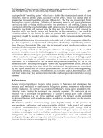
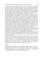
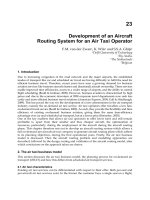
Fig. 7. Number of ICP steps required for a typical tracking sequence.
Fig. 8. Time consumption per ICP step vs. number of ICP steps.
The computational effort for one frame depends first of all on the number of ICP steps
needed. The number of iterations again depends on the body displacement between two
consecutive frames. Fig. 7 shows the number of required ICP steps during a typical tracking
sequence for a human body model. During phases without large movements, one iteration
is enough to approximate the body pose (frame 500 to 570). Extensive movements are
compensated by more ICP iteration steps per frame (650 to 800).
The required time per frame obviously increases with the number of needed ICP steps. This
relation is shown in Fig. 8. A maximum number of 6 ICP steps has turned out to be a good
trade-off between time consumption per frame and tracking accuracy. This leads to a frame
period of 20 - 70ms, which corresponds to a frame-rate of 14.2 to 50Hz. The maximum
frame-rate in our framework is only constrained by the camera frame-rate, which is 30Hz.
518 Humanoid Robots, New Developments
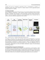
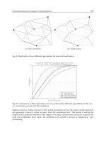
Fig. 9. Time consumption per frame vs. number of body measurements.
The relation between the number of body measurements and the computational effort for
one ICP step is depicted in Fig. 9. For each measurement of the target, several computations
have to be carried out. This leads to the dependency in Fig. 9. As expected, the time scales
linearly with the number of measurements.
These results show that the presented tracking approach is able to incorporate several
thousand measurements with reasonable computational effort. One disadvantage of the
depicted iterative process is the negative dependency between target displacement and
computational effort: The faster the target moves, the longer the tracking needs for one
frame, which again leads to larger displacements due to the low frame-rate.
To overcome this, one has to find a good trade-off between accuracy and frame-rate. This
compromise depends on the tracking target characteristics, as well as on the application
which utilizes the Human Motion Capture data. It is also possible to switch between
different behaviours, taking into account the requirements the applications which depend
on the Motion Capture data: in case the data is used for physical interaction (e.g. handing
over objects), the required accuracy is high, along with usually low dynamics. On the other
hand, if the target is only to observe a human in the robot’s environment, the required
accuracy is low, but the person moves with high velocity.
8. Discussion and conclusion
This paper has proposed a geometric human body model, a joint model and a way for
fusion of different input cues for tracking of an articulated body. The proposed algorithm is
able to process 3d as well as 2d input data from different sensors like ToF-cameras, stereo or
monocular images. It is based on a 3d body model which consists of a set of degenerated
cylinders, which are connected by an elastic bands joint model. The proposed approach runs
in real-time. It has been demonstrated with a human body model for pose tracking.
The main novelty and contribution of the presented approach lies in the articulated body
model based on elastic bands with soft stiffness constraints, and in the notion of point
correspondences as a general measurement and model format. Different joint behaviours
A Human Body Model for Articulated 3D Pose Tracking 519
can be modelled easily by distributing the elastic bands along two axes in the joint. The joint
constraints are incorporated in the ICP as artificial measurements, so measurements and
model knowledge are processed identically. The model can also be refined by adding
cylindrical primitives for hands, fingers and feet. This is reasonable if the accuracy and
resolution of the available sensors are high enough to resolve e.g. the hand posture, which is
not the case in our approach due to the large distance between human and robot and the
low measurement resolution.
The idea of introducing artificial correspondences into the fitting step can even be exploited
further. Current works include further restriction of the joints in angular space by adding
angular limits to certain degrees of freedom, which are maintained valid by artificial point
correspondences. These will be generated and weighted depending on the current body
configuration.
Our implementation of the described tracking framework has been released under the GPL
license, and is available online at wwwiaim.ira.uka.de/users/knoop/VooDoo/doc/html/,
along with sample sequences of raw sensor data and resulting model sequences.
9. References
Aggarwal, J. K.; Cai, Q. (1999) Human motion analysis: A review, Computer Vision and Image
Understanding: CVIU, vol. 73, no. 3, pp. 428–440.
Azad, P.; Ude, A.; Dillmann, R.; Cheng, G. (2004) A full body human motion capture system
using particle filtering and on-the-fly edge detection, in Proceedings of the IEEE-
RAS/RSJ International Conference on Humanoid Robots. Santa Monica, USA.
Besl, P. J.; McKay, N. D. (1992) A method for registration of 3-d shapes, IEEE Transactions on
pattern analysis and machine intelligence, vol. 14, no. 2, pp. 239–256, February.
Bobick, A. F.; Davis, J. W. (2001) The recognition of human movement using temporal templates,
IEEE Transactions on Pattern Analysis and Machine Intelligence, no. 3, pp. 257–
267.
Calinon, S.; Billard, A. (2005), Recognition and reproduction of gestures using a probabilistic
framework combining PCA, ICA and HMM, in Proceedings of the International
Conference on Machine Learning (ICML), Bonn, Germany
Cheung, G. K. M.; Baker, S.; Kanade, T. (2003) Shape-from-silhouette of articulated objects and its
use for human body kinematics estimation and motion capture, in Computer Vision and
Pattern Recognition.
CSEM (2006) Swissranger website.
Demirdjian, D.; Darrell, T. (2002) 3-d articulated pose tracking to untethered deictic references, in
Multimodel Interfaces, pp. 267–272.
Demirdjian, D. (2003) Enforcing constraints for human body tracking, in Conference on
Computer Vision and Pattern Recognition, Workshop Vol. 9, Madison, Wisconsin,
USA, pp. 102–109.
Deutscher, J.; Blake, A.; Reid, I. (2000), Articulated body motion capture by annealed particle
filtering, in Computer Vision and Pattern Recognition (CVPR), Hilton Head, USA,
pp. 2126–2133.
Ehrenmann, M.; Zöllner, R.; Rogalla, O.; Vacek, S.; Dillmann, R. (2003). Observation in
programming by demonstration: Training and execution environment, in Proceedings of
Third IEEE International Conference on Humanoid Robots, Karlsruhe and Munich,
Germany.
520 Humanoid Robots, New Developments
Fritsch, J.; Lang, S.; Kleinehagenbrock, M.; Fink, G. A.; Sagerer, G. (2002) Improving adaptive
skin color segmentation by incorporating results from face detection, in Proc. IEEE Int.
Workshop on Robot and Human Interactive Communication (ROMAN). Berlin,
Germany
Fritsch, J.; Kleinehagenbrock, M.; Lang, S.; Plötz, T.; Fink, G.A.; Sagerer, G. (2003), Multi-
modal anchoring for human-robot-interaction, Robotics and Autonomous Systems,
Special issue on Anchoring Symbols to Sensor Data in Single and Multiple Robot
Systems, vol. 43, no. 2–3, pp. 133–147.
Gavrila, D. M. (1999) The visual analysis of human movement: A survey, Computer Vision and
Image Understanding, vol. 73, no. 1, pp. 82–98.
H|Anim (2003), Information technology — Computer graphics and image processing — Humanoid
animation (H-Anim), Annex B, ISO/IEC FCD 19774, Humanoid Animation Working
Group, Specification.
Horn, B. K. P. (1987) Closed-form solution of absolute orientation using unit quaternions, Optical
Society of America Journal A, vol. 4, pp. 629–642, Apr. 1987.
Knoop, S.; Vacek, S. & Dillmann, R. (2005). Modelling Joint Constraints for an Articulated 3D
Human Body Model with Artificial Correspondences in ICP, Proceedings of the
International Conference on Humanoid Robots (Humanoids 2005), Tsukuba, Japan,
December 2005, IEEE-RAS
Knoop, S.; Vacek, S. & Dillmann, R. (2006). Sensor Fusion for 3D Human Body Tracking with an
Articulated 3D Body Model. Proceedings of the IEEE International Conference on
Robotics and Automation (ICRA), Orlando, Florida, May 2006
Knoop, S.; Vacek, S. & Dillmann, R. (2006). Sensor fusion for model based 3D tracking.
Proceedings of the IEEE International Conference on Multisensor Fusion and
Integration for Intelligent Systems (MFI), Heidelberg, Germany, September 2006
Moeslund, T. B.; Granum, E. (2001) A survey of computer vision-based human motion capture,
Computer Vision and Image Understanding, vol. 81, no. 3, pp. 231–268.
Ramanan, D.; Forsyth, D. A. (2003) Finding and tracking people from the bottom up, in
Computer Vision and Pattern Recognition, vol. 2, 18-20 June, pp. II–467–II–474.
Sidenbladh, H. (2001) Probabilistic tracking and reconstruction of 3d human motion in monocular
video sequences, Ph.D. dissertation, KTH, Stockholm, Sweden.
Wang, L.; Hu, W.; Tan, T. (2004) Recent developments in human motion analysis, Pattern
Recognition, vol. 36, no. 3, pp. 585–601, 2003.and Electronics Engineers.
29
Drum Beating and a Martial Art Bojutsu
Performed by a Humanoid Robot
Atsushi Konno, Takaaki Matsumoto, Yu Ishida, Daisuke Sato & Masaru Uchiyama
Tohoku University
Japan
1. Introduction
Over the past few decades a considerable number of studies have been made on impact
dynamics. Zheng and Hemami discussed a mathematical model of a robot that collides with an
environment (Zheng & Hemami, 1985). When a robot arm fixed on the ground collides with a
hard environment, the transition from the free space to constrained space may bring instability
in the control system. Therefore, the impact between robots and environments has been the
subject of controversy. Asada and Ogawa analyzed the dynamics of a robot arm interacting
with an environment using the inverse inertia matrices (Asada & Ogawa, 1987). In the early
90’s, the optimum approach velocity for force-controlled contact has been enthusiastically
studied (Nagata et al., 1990, Kitagaki & Uchiyama, 1992). Volpe and Khosla proposed an impact
control scheme for stable hard-on-hard contact of a robot arm with an environment (Volpe &
Khosla, 1993). Mills and Lokhorst proposed a discontinuous control approach for the tasks that
require robot arms to make a transition from non-contact motion to contact motion, and from
contact motion to non-contact motion (Mills & Lokhorst, 1993). Walker proposed measures
named the dynamic impact measure and the generalized impact measure to evaluate the effects
of impact on robot arms (Walker, 1994). Mandal and Payandeh discussed a unified control
strategy capable of achieving a stable contact against both hard and soft environment (Mandal
& Payandeh, 1995). Tarn et al. proposed a sensor-referenced control method using positive
acceleration feedback and switching control strategy for robot impact control (Tarn et al., 1996).
Space robots does not have fixed bases, therefore, an impact with other free-floating objects may
bring the space robots a catastrophe. In order to minimize the impulsive reaction force or
attitude disturbance at the base of a space robot, strategies for colliding using reaction null-
space have been proposed (Yoshida & Nenchev, 1995, Nenchev & Yoshida, 1998).
Most of the researches have been made to overcome the problems introduced by impacts
between robots and environments. Some researchers have tried to use the advantages of
impacts. When a robot applies a force statically on an environment, the magnitude of force
is limited by the maximum torque of the actuators. In order to exert a large force on the
environment beyond the limitation, applying impulsive force has been studied by a few
researchers. Uchiyama performed a nail task by a 3-DOF robotic manipulator (Uchiyama,
1975). Takase et al. developed a two-arm robotic manipulator named Robot Carpenter, and
performed sawing a wooden plate and nailing (Takase, 1990). Izumi and Hitaka proposed to
use a flexible link manipulator for nailing task, because the flexible link has an advantage in
absorbing an impact (Izumi & Kitaka, 1993).
522 Humanoid Robots, New Developments
However, those works mentioned above were done using robotic manipulators fixed on the
ground except for space robots, and thus, there was no need to take care about loosing a
balance. Humanoid robots are expected to work on human’s behalf. If a humanoid robot can
do heavy works utilizing an impulsive force as well as a human does, the humanoid robot
will be widely used in various application fields such as constructions, civil works, and
rescue activities.
The first attempt on an impact motion by a humanoid robot was reported in (Hwang et al.,
2003). Matsumoto et al. performed a Karate-chop using a small humanoid robot and broke
wooden plates (Matsumoto et al., 2004). In order for a legged robot to effectively exert a
large force to an environment without loosing a balance, working posture is important.
Tagawa et al. proposed a firm standing of a quadruped for mobile manipulation (Tagawa et
al., 2003). Konno et al. discussed an appropriate working posture of a humanoid robot
(Konno et al., 2005).
This chapter addresses an impact motion performed by a humanoid robot HRP-2. A drum
beating is taken as a case study, because it is a typical task that requires large impulsive
forces. The drum beating motion is carefully designed to synchronize with music. The drum
beating and a Japanese martial art Bojutsu were performed by a humanoid robot HRP-2 in
the Prototype Robot Exhibition at Aichi Exposition 2005.
2. Why and Where Is an Impulsive Force Needed?
In order to show the advantages of using an impulsive force, a task of pushing a wall is
taken as an example in this section. A model of a humanoid robot HRP-1 (the HONDA
humanoid robot P3) is used in a simulation.
Fig. 1 shows the snapshots in a simulation in which the humanoid robot HRP-1 quasi-
statically pushes a wall, while Fig. 2 shows the snapshots in a simulation in which the
HRP-1 dynamically pushes a wall moving a body forward. In the simulation illustrated in
Fig. 1, the body is fixed so that the projection of the centre of gravity (COG) comes on the
middle of the fore foot and rear foot, while in the simulation illustrated in Fig. 2, the body
is moved so that the projection of COG moves from the centre of rear foot to the centre of
fore foot.
The results of the simulations are plotted in Fig. 3. Fig. 3 (a) shows the forces generated at
the wrist (equal and opposite forces are generated on the wall) when the humanoid robot
exerts a quasi-static force on a wall, while (b) shows the forces at the wrist when the
humanoid robot dynamically exerts a force.
(a) (b) (c) (d)
Fig. 1. A humanoid robot quasi-statically pushes a wall. The body is fixed so that the
projection of the center of gravity (COG) comes on the middle of the fore foot and rear foot.
(a) at 0.0 [s], (b) at 2.0 [2], (c) at 4.0 [s], and (d) at 6.0 [s].
Drum Beating and a Martial Art Bojutsu Performed by a Humanoid Robot 523
(a) (b) (c) (d)
Fig. 2. A humanoid robot pushes a wall moving the body to apply an impulsive force. In
order to accumulate momentum, the body is moved so that the projection of COG moves
from the center of rear foot to the center of fore foot. (a) at 0.0 [s], (b) at 2.0[2], (c) at 4.0 [s],
and (d) at 6.0 [s].
As seen in Fig. 3, when the humanoid robot dynamically exerts a force on a wall,
approximately 1.5 times larger force is generated compared with the case when the
humanoid robot quasi-statically exerts a force.
There is a strong demand for the formulation of the impact dynamics of a humanoid robot
to solve the following problems:
• Working postures: An optimum working posture at the impact tasks must be
analyzed in order to minimize the angular momentum caused by an impulsive
force. The angular momentum is more crucial than the translational momentum,
because a humanoid robot easily falls down by a large angular momentum.
• Impact motion synthesis: Appropriate impact motions of a humanoid robot must be
synthesized based on multibody dynamics, to exert a large force on an
environment.
• Stability analysis: Exerting a large force on an environment, a humanoid robot must
keep the balance. Therefore, stability analysis for the impact tasks is inevitable.
• Shock absorbing control: In order to minimize the bad effect caused by the
discontinuous velocity, shock absorbing control algorithms must be studied.
• Enrichment of applications: Applications of the impact tasks must be developed to
clearly show the advantages of using the impulsive force.
-500
-400
-300
-200
-100
0
100
200
300
0 1 2 3 4 5
Force [N]
Time [s]
X
Y
Z
-500
-400
-300
-200
-100
0
100
200
300
0 1 2 3 4 5 6
Force [N]
Time [s]
X
Y
Z
(a) (b)
Fig. 3. Force generated at the wrist. (a) When the humanoid robot exerts a quasi-static force
on a wall. (b) When the humanoid robot exerts an impulsive force on a wall.
524 Humanoid Robots, New Developments
3. A Humanoid Robot HRP-2 and Control System Software
3.1 Specifications of the HRP-2
A humanoid robot HRP-2 was developed in the Humanoid Robotics Project (1998–2002)
being supported by the Ministry of Economy, Trade and Industry (METI) through New
Energy and Industrial Technology Development Organization (NEDO). The total
robotic system was designed and integrated by Kawada Industries, Inc. and Humanoid
Research Group of the National Institute of Advanced Industrial Science and
Technology (AIST).
The height and weight of the HRP-2 are respectively 154 cm and 58 kg including
batteries. The HRP-2 has 30 degrees of freedom (DOF). Please see the official web
page of the HRP-2 ( ) for more
details.
In order to perform the drum beating and Bojutsu, small modifications are applied to the
HRP-2. The arrangement of the wrist DOF is modified from the original, i.e. the last DOF at
the wrist is pronated 90
o
. Furthermore, gloves are developed and attached to the hands to
grip firmly the sticks.
3.2 Control system software
The control system software of the HRP-2 is supplied and supported by General Robotics
Inc. The control system software provides a controller that can be used with the CORBA
servers of OpenHRP (Hirukawa et al., 2003). As shown in Fig. 4, the controller is composed
of many plugin softwares. The control system software also includes the I/O access library
to access the lower level functions of the robot and a VRML simulator model of the HRP-2
and various utilities.
Fig. 4. Control system software of the HRP-2 with OpenHRP (the figure is quoted from
/>Foundational plugins such as Kalman Filter, Sequential Playback, Walk Stabilizer, Pattern Generator,
Dynamics, Logger, and ZMPSensor are also included in the control system software, however,
users can develop own functions as a plugin to enrich the humanoid robot motions. Please see
the official web page for
more details of the control software.
Drum Beating and a Martial Art Bojutsu Performed by a Humanoid Robot 525
4. Drum Beating
4.1 Primitive poses and motions
In order to generate drum beating motions of the humanoid robot HRP-2, the motion is
decomposed into four primitive poses or motions: (a) initial pose, (b) swing, (c) impact, and
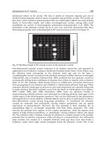
(d) withdrawing, as shown in Fig. 5. Among the four primitive motions, impact and
withdrawing are important to exert an impulsive force.
As presented in Fig. 6, three different swing patterns, (a) small swing, (b) middle swing and
(c) big swing, are generated sharing the poses for the impact and withdrawing.
For these swing patterns, three different initial poses are given and the poses to pass
through in swing motion are designed. Cubic spline is used to interpolate the given
poses.
(a) (b) (c) (d)
Fig. 5. Four primitive poses or motions in a drum beating. (a) Initial pose. (b) Swing. (c)
Impact. (d) Withdrawing.
4.2 Synchronization with music
The swing motion must be synchronized with music in the drum beating. For the
synchronization, a beat timing script is prepared for each tune. An example of the script is
listed as follows:
0.500 RS
1.270 LM
1.270 RM
0.635 LS
0.500 END
The numbers listed in the first column indicate the interval (s) to the next beating. The
symbols listed in the second column indicate the way of beating. The first character ’R’ or ’L’
indicates the arm to move (Right or Left), while the second character ’S’, ’M’, ’B’, or ’E’
indicates the kinds of swing (Small swing, Middle swing, Big swing, or Edge beating, see
Fig. 6).
For example, the third line of the script “1.270 RM” indicates “beat the drum after 1.270 s
using the middle swing of the right arm.” The period between the impact and the previous
pose is fixed to 0.1 s to achieve the maximum speed at the impact. As shown in Fig. 6 (b),
seven intermediate poses are designed for the middle swing between the initial pose and the
impact, therefore, if the duration is specified to 1.270 s, each period ΔT
M
between the poses
is calculated as follows:
526 Humanoid Robots, New Developments
−−
Δ= =
duration 0.1 1.270 0.1
.
number of poses 7
M
T (1)
The duration time varies depending upon a tune.
There are two restrictions in the script: (i) the first beating must be RS (small swing of right
arm), (ii) right arm and left arm must be alternating to beat.
0.1 [s] 0.1 [s]
Impact Withdrawing
(a)
(b)
(c)
Initial pose
Swing
Δ
M
T
Δ
B
T
Δ
S
T Δ
S
T
Δ
S
T
Duration indicated in the beat timing script
0.1 [s] 0.1 [s]
Impact WithdrawingInitial pose Swing
Duration indicated in the beat timing script
0.1 [s] 0.1 [s]
Impact WithdrawingInitial pose Swing
Duration indicated in the beat timing script
Δ
M
T Δ
M
TΔ
M
T Δ
M
TΔ
M
T Δ
M
T
Δ
B
T Δ
B
TΔ
B
T Δ
B
TΔ
B
T Δ
B
TΔ
B
T Δ
B
TΔ
B
T Δ
B
T
Fig. 6. Three swing patterns. The periods between impact and the previous pose, and
between withdrawing and impact are fixed to 0.1 [s]. Other periods denoted by ΔT
S
, ΔT
M
,
ΔT
B
, are computed from the duration indicated in the beat timing script. (a) Small swing. (b)
Middle swing. (c) Big swing.
4.3 Control software
Fig. 7 presents the flow of the control system. The components marked with red boundary
boxes are developed in this work.
Firstly, wav files of the three tunes are prepared: (i) ware wa umi no ko (I am a son of the sea),
(ii) Tokyo ondo (Tokyo dance song), and (iii) mura matsuri (village festival). They are very old
and traditional tunes, and thus, copyright free. As soon as the Speak Server receives a queue
from the robot control system, the server starts playing the tune. The queue is used to
synchronize the tune with the drum beating motion.
Secondly, the timings of beating are scheduled by hand. In order to strictly count the
timing, a time keeping software is newly developed. The time keeping software counts the
rhythm of a tune. The timings of the beating are described in a script file as mentioned in
Section 2.
Thirdly, a plugin software is developed as a shared object to generate drum beating motions
interpreting the beat timing script.
Fourthly, interpolating the given poses presented in Fig. 6 using cubic spline, trajectories of
all joints are produced online. The produced trajectories are given to the humanoid robot
through a plugin SeqPlay.
Drum Beating and a Martial Art Bojutsu Performed by a Humanoid Robot 527
Made by hand
0.635 RS
1.270 LM
1.270 RM
0.635 LS
0.5 END
0.635 RS
1.270 LM
1.270 RM
0.635 LS
.
.
0.5 END
Beat timing script
TimeKeeper.exe
TimingGenerator3_3.so
TokyoOndo.wav
TokyoOndo.txt
ArmPluginCS.so
Spliner.o
Music player
SpeakServer
OpenHRP
Queue
speak.so
CORBA
call
seqplay.so
Jython script
Music file
Interpreting the beat timing
script, the timings to pass
through the given poses
are adjusted.
Given
poses and
timings
Cubic spline interpolation
A sequence of joint motions
is generated interpolating
the given postures.
Robot
Fig. 7. A software diagram. The components marked with red boundary boxes are
developed in this work.
4.3 Resultant joint trajectories
The reference and resultant joint trajectories of the elbow and wrist joints of the right arm
are plotted in Fig. 8. The error in the impact time was approximately 30 [ms], which was not
significant in the synchronization with music.
-70
-60
-50
-40
-30
-20
-10
0
0 0.1 0.2 0.3 0.4 0.5 0.6 0.
7
Reference elbow joint
Reference wrist joint
Resultant elbow joint
Resultant wirst joint
Time [s]
Joint angle [ ]
o
Fig. 8. A software diagram. The components marked with red boundary boxes are
developed in this work.
528 Humanoid Robots, New Developments
As can be seen in Fig. 7, during the last 0.1 [s] before the impact (approximately from 0.5 to
0.6 [s]), gradients of the joint trajectories are steep compared with other periods. Since the
period between the impact and the previous pose is set to 0.1 [s], maximum joint speed is
almost achieved.
5. A Japanese Martial Art Bojutsu
In martial arts, impulsive forces are frequently used to fight with an antagonist. A Japanese
martial art Bojutsu was also demonstrated by the humanoid robot HRP-2 in Aichi
Exposition, although an impact was not performed in the demonstration. Some dynamic
motions used in the demonstration are presented in Fig. 9.
0.0 [s]
2.0 [s] 4.0 [s] 6.0 [s]
(a)
0.0 [s]
2.0 [s] 4.0 [s] 6.0 [s]
(b)
0.0 [s]
1.0 [s] 2.0 [s] 3.0 [s]
4.0 [s]
(c)
Fig. 9. The Japanese martial art Bojutsu motion patterns. (a) Thrusting a staff weapon
rightward. (b) Thrusting a staff weapon leftward. (c) Banging down a staff weapon.
6. Demonstration at Aichi Exposition
The Prototype Robot Exhibition was held for 11 days from June 9 to 19, at the Morizo and
Kiccoro Exhibition Center, a convention venue in the Aichi Expo site. The Prototype Robot
Exhibition was organized by the Japan Association for the 2005 World Exposition and the
New Energy and Industrial Technology Development Organization (NEDO). 63 prototypes
performed demonstrations during the period.
Drum Beating and a Martial Art Bojutsu Performed by a Humanoid Robot 529
The drum beating and Bojutsu demonstration was performed twice a day in the Prototype
Robot Exhibition (Fig. 10).
(a) (b)
Fig. 10. Demonstrations at Aichi Exposition 2005. (a) Drum beating performance. (b) A
Japanese martial art Bojutsu performance.
7. Conclusion
This chapter proposed to utilize an impulsive force for humanoid robots to exerts a large
force beyond the torque limitations of actuators. The problems of the impact tasks to be
solved in the future work were brought up in Section 2.
A drum beating is taken as a case study, because it is a typical task that requires large
impulsive forces. The details of the drum beating and a Japanese martial art Bojutsu performed
by a humanoid robot HRP-2 in the Aichi Exposition were presented in this paper.
8. Acknowledgement
Authors would like to express special thanks to the staffs of Kawada Industries, Inc. and
General Robotics Inc. for their kind and sincere support in this project. Authors also would
like to express thanks to all the staffs who are related to the Prototype Robot Exhibition.
9. References
Asada, H. & and Ogawa, K. (1987). ON THE DYNAMIC ANALYSIS OF A MANIPULATOR
AND ITS END EFFECTOR INTERACTING WITH THE ENVIRONMENT,
Proceedings of the IEEE Int. Conf. on Robotics and Automation, pp. 751–756
Hirukawa, H.; Kanehiro, F. & Kajita, S. (2003). Open HRP: Open Architecture Humanoid
Robotics Platform, Robotics Research, STAR 6, Springer-Verlag, Jarvis, R. A. &
Zelinsky, A. Eds., pp. 99–112
Hwang, Y.; Konno, A. & Uchiyama, M. (2003). Whole Body Cooperative Tasks and Static
Stability Evaluations for a Humanoid Robot, Proceedings of IEEE/RSJ Int. Conf. on
Intelligent Robots and Systems, pp. 1901–1906
Izumi, T. & Kitaka, Y. (1993). Control of a Hitting Velocity and Direction for a Hammering
Robot Using a Flexible Link, Journal of the RSJ, Vol. 11, No. 3, pp. 436–443, (In
Japanese).
530 Humanoid Robots, New Developments
Kitagaki, K. & Uchiyama, M. (1992). OPTIMAL APPROACH VELOCITY OF END-
EFFECTOR TO THE ENVIRONMENT, Proceedings of the IEEE Int. Conf. on Robotics
and Automation, pp. 1928–1934
Konno, A.; Hwang, Y, Tamada, S. & Uchiyama, M. (2005). Working Postures for Humanoid
Robots to Generate Large Manipulation Force, Proceedings of IEEE/RSJ Int. Conf. on
Intelligent Robots and Systems, pp. 1788–1793
Mandal, N. & Payandeh, S. (1995). Control Strategies for Robotic Contact Tasks: An
Experimental Study, Journal of Robotic Systems, Vol. 12, No. 1, pp. 67–92
Matsumoto, T.; Konno, A., Gou, L. & Uchiyama, M. (2006). A Humanoid Robot that Breaks
Wooden Boards Applying Impulsive Force, Proceedings of 2005 IEEE/RSJ Int. Conf.
on Intelligent Robots and Systems, pp. 5919–5924
Mills, J. K. & Lokhorst, D. M. (1993). Control of Robotic Manipulators During General Task
Execution: A Discontinuous Control Approach, The Int. Journal of Robotics Research,
Vol. 12, No. 2, pp. 146–163
Nagata, K.; Ogasawara, T. & Omata, T. (1990). Optimum Velocity Vector of Articulated
Robot for Soft Bumping, Journal of the SICE, Vol. 26, No. 4, pp. 435–442, (In
Japanese)
Nenchev, D. N. & Yoshida, K. (1998). Impact Analysis and Post Impact Motion Control
Issues of a Free-Floating Space Robot Contacting a Tumbling Object, Proceedings of
IEEE Int. Conf. on Robotics and Automation, pp. 913–919
Tagawa, T.; Aiyama, Y. & Osumi, H. (2003). Firm Standing of Legged Mobile Manipulator,
Proceedings of IEEE Int. Conf. on Robotics and Automation, pp. 2031–2036
Takase, K. (1990). Task Execution by Robot Hand, Journal of the SICE, Vol. 29, No. 3, pp. 213–
219, (In Japanese).
Tarn, T J.; Wu, Y., Xi, N. & Isidori, A. (1996). Force Regulation and Contact Transition
Control, IEEE Control Systems, Vol. 16, No. 1, pp. 32–40
Uchiyama, M. (1975). A Control Algorithm Constitution Method for Artificial Arm and
Dynamic Control Modes, Biomechanism 3, University of Tokyo Press, pp. 172–181,
(In Japanese)
Volpe, R. & Khosla, P. (1993). A Theoretical and Experimental Investigation of Impact
Control for Manipulators, The Int. Journal of Robotics Research, Vol. 12, No. 4, pp.
351–365
Walker, I. D. (1994). Impact Configurations and Measures for Kinematically Redundant and
Multiple Armed Robot System, IEEE Transactions on Robotics and Automation, Vol.
10, No. 5, pp. 670–683
Yoshida K. & Nenchev, D. N. (1995). Space Robot Impact Analysis and Satellite-Base
Impulse Minimization Using Reaction Null-Space, Proceedings of IEEE Int. Conf. on
Robotics and Automation, pp. 1271–1277
Zheng, Y F. & Hemami, H. (1985). Mathematical Modeling of a Robot Collision with its
Environment, Journal of Robotic Systems, Vol. 2, No. 3, pp. 289–307
30
On Foveated Gaze Control and Combined Gaze
and Locomotion Planning
Kolja Kühnlenz, Georgios Lidoris, Dirk Wollherr, and Martin Buss
Institute of Automatic Control Engineering, Technische Universität München
D-80290 München, Germany
1. Introduction
This chapter presents recent research results of our laboratory in the area of vision and
locomotion coordination with an emphasis on foveated multi-camera vision. A novel active
vision planning concept is presented which coordinates the individual devices of a foveated
multi-camera system. Gaze direction control is combined with trajectory planning based on
information theoretic criteria to provide vision-based autonomous exploring robots with
accurate models of their environment.
With the help of velocity and yaw angle sensors, mobile robots can update the internal
knowledge about their current position and orientation from a previous time step; this
process is commonly referred to as dead-reckoning. Due to measurement errors and
slippage these estimations are erroneous and position accuracy degrades over time causing
a drift of the estimated robot pose. To overcome the drift problem it is common to take
absolute measurements evaluating visual information, which are fused dynamically with
the odometry data by applying Kalman-filter or other techniques, e.g. (Dissanayake et al.,
2001). The use of active vision systems for navigation is state-of-the-art providing a
situation-related selective allocation of vision sensor resources, e.g. (Davison & Murray,
2002; Seara et al., 2003; Vidal-Calleja et al., 2006). Active vision systems comprising only one
type of vision sensor face a trade-off between field of view and measurement accuracy due
to limitations of sensor size and resolution, and of computational resources. In order to
overcome this drawback the combined use of several vision devices with different fields of
view and measurement accuracies is known which is called foveated, multi-resolution, or
multi-focal vision, e.g. cf. (Dickmanns, 2003; Kühnlenz et al., 2006; Ude et al., 2006). Thereby,
the individual vision devices can be independently controlled according to the current
situation and task requirements. The use of foveated active vision for humanoid robot
navigation is considered novel.
Active vision is also frequently utilized in the context of robotic exploration. Yet, gaze control
and locomotion planning are generally decoupled in state-of-the-art approaches to simultaneous
localization and mapping (SLAM). An integrated locomotion planning and gaze direction
control concept maximizing the collected amount of information is presented in the second part
of this chapter. This strategy results in more accurate autonomously acquired environment
representations and robot position estimates compared to state-of-the-art approaches.
The chapter is organized as follows: In Section 2 vision-based localization and mapping in
the context of humanoid robots is surveyed; Section 3 is concerned with foveated multi-
532 Humanoid Robots, New Developments
camera coordination; novel concepts of gaze control and path planning coordination are
presented in Section 4; evaluation studies comparing the novel concepts to conventional
planning approaches and vision systems are presented in Section 5; conclusions are given in
Section 6.
2. Vision-Based Localization and Mapping for Humanoid Robots
Most state-of-the-art humanoid robots are equipped with vision systems. The benefits of
using these vision systems for providing absolute measurements of the robot pose in the
environment are obvious: pose information on landmarks is provided and no additional
devices as, e.g., laser scanners are necessary. Being equipped with internal sensors - angular
sensors in the joints and widely used gyros and accelerometers in the trunk - humanoid
robots are basically capable of dead-reckoning, i.e. the ability to update position and
orientation known from previous measurements. Thus, common simultaneous localization
and mapping techniques are applicable which are covered by common literature, e.g. (Sabe
et al., 2004; Ozawa et al., 2005; Thomson & Kagami, 2005; Stasse et el., 2006).
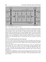
Fig. 1. Humanoid robot navigation scenario.
A fundamental aspect in simultaneous localization and mapping for humanoid walking is
the formulation of a state-space model accounting for the footstep sequences of the robot. In
vision-based SLAM, the system state, i.e. the robot pose and environment point positions,
are predicted based on the dead-reckoning model of the mobile robot. Common Kalman-
filter techniques are applied in order to obtain more accurate estimations accounting for
uncertainties in the robot locomotion. Whenever visual measurements of environmental
points are taken, updates of the robot state are computed. Changing ground contact
situations of the feet, however, result in different kinematic chains from a world reference
frame to measured environment points. This discontinuous movement of the humanoid
robot requires an adaptation of the filter formulation. In earlier works we proposed a hybrid
formulation of the state-space model in order to capture this locomotion principle (Seara et
al., 2003). Thereby, the robot reference frame is placed in the foot currently in contact with
the ground and is switched whenever the supporting foot changes. The dead-reckoning
model is expressed by
On Foveated Gaze Control and Combined Gaze and Locomotion Planning 533
kkxkkskkk
duxfxx
γ
γ
),,()(
,
+−=
+
1
1
, (1)
where state-vector x contains the robot foot pose and the landmark positions, d represents
system noise capturing dead-reckoning uncertainties, and
γ
∈{0; 1} is a binary variable
indicating a change of the supporting foot when
γ
=1. The commanded step u is expressed
by
[]
T
ksFksFksFk
yxu
,,,
θ
=
, (2)
including the commanded step position [x
s
y
s
]
T
and orientation
θ
s
with respect to the current
supporting foot frame S
F
. Figure 1 schematically shows a typical SLAM situation of a
humanoid robot with the reference frame currently placed in the left foot.
In vision-based SLAM field of view restrictions of the vision device strongly limit the
number of landmarks to be observed simultaneously. Yet, a larger field of view can only be
realized accepting a lower measurement accuracy of the vision device mainly due to
limitations of sensor size and resolution. Therefore, we propose the use of several vision
devices which provide different fields of view and accuracies and a novel gaze control
concept for coordinating the individual vision devices in order to provide both, large field of
view and high measurement accuracy, simultaneously. These foveated active vision
concepts for robot navigation are discussed in the following section.
3. Foveated Multi-Camera Coordination
3.1 Active Vision in SLAM
In order to gather an optimal situation-dependent amount of information the control of the
vision system pose is common. To date, there are only few works in the area of active
vision-based SLAM, e.g. (Davison & Murray, 2002; Se et el., 2002; Vidal-Calleja et el., 2006)
which are based on measures representing the information gathered with respect to the
SLAM task. All these approaches are greedy strategies only evaluating the current situation
without considering future planning steps. In order to obtain an optimal gaze direction
considering also some future planning steps, we proposed a gaze direction planning
strategy with limited time horizon (Lidoris et al., 2006). Furthermore, in earlier works (Seara
et al., 2003) we introduced a gaze control strategy considering concurrent tasks, localization,
and obstacle avoidance for humanoid robots in order to account for navigation in physical
environments.
3.2 Foveated Active Vision
Vision systems comprising only one type of vision sensors face a tradeoff between
measurement accuracy and field of view due to limitations of sensor size and computational
resources for image processing. Accuracy and field of view are mainly determined by the
focal-length of the lens or mirror optics, respectively. Within the context of robot navigation
this tradeoff implies a compromise between localization accuracy and keeping a large part
of the scene in view.
With an active vision system this tradeoff could be compensated providing that a
sufficiently accurate map of relevant landmarks or structures of interest to be observed is
known a priori. Then the highest available focal-length and, thus, the highest measurement
accuracy could be chosen. If additionally very fast gaze shifts can be realized, the narrow
field of view would be acceptable as visual attention can be directed dynamically towards
534 Humanoid Robots, New Developments
the most relevant structure in the current situation. Yet, in a variety of scenarios this
approach is unsuitable or even unrealizable. In at least partially unknown environments
and in exploration scenarios a sufficient map is not available and thus has to be created
online. However, due to the strongly limited field of view the detection of new objects of
potential interest is hardly possible. Another aspect are potentially relevant or even
dangerous objects or activities in the local surroundings of the robot which cannot be
detected.
In order to overcome the common drawback of trading field of view versus measurement
accuracy, the combination of wide-angle and telephoto vision devices has been suggested.
Such systems provide at the same time both, an observation of a large part of the
environment and a selective examination with high accuracy. In common literature these
systems are referred to as foveated, multi-resolution or multi-focal systems. The individual
vision devices may be fixed with respect to each other or may be independently motion
controllable in one or more degrees of freedom. Most common embodiments of foveated
systems are used in state-of-the-art humanoid robots comprising two different cameras
combined in each eye which are aligned in parallel, e.g. (Brooks et al., 1999; Ude et al., 2006;
Vijayakumar et al., 2004). Systems for ground vehicles, e.g. (Apostoloff & Zelinsky, 2002;
Maurer et al., 1996; Dickmanns, 2003) are another prominent class. An upcoming area are
surveillance systems which strongly benefit from the combination of large scene overview
and selective observation with high accuracy, e.g. (Bodor et al., 2004; Davis & Chen, 2003;
Elder et al., 2004; Jankovic & Naish, 2005; Horaud et al., 2006). An embodiment with
independent motion control of three vision devices with a total of 6 degrees-of-freedom
(DoF) is the camera head of the humanoid robot L
OLA developed at our laboratory which is
shown in Figure 2 providing more flexibility and, due to directly driven gimbals, faster
camera motions than other known systems, cf. e.g. (Kühnlenz et al., 2006).
Fig. 2. Multi-focal vision system of humanoid LOLA (Kühnlenz et el. 2006).
Most known methods for active vision control in the field of foveated vision are concerned
with decision-based mechanisms to coordinate the view direction of a telephoto vision
device based on evaluations of visual data of a wide-angle device. For a survey on state-of-
the-art methods cf. (Kühnlenz, 2006). A first approach towards a coordination of foveated
multi-camera view direction planning for humanoid walking has been investigated in our
laboratory which is presented in the following sections.
On Foveated Gaze Control and Combined Gaze and Locomotion Planning 535
Fig. 3. Humanoid robot navigation scenario with multi-camera vision.
3.3 Considerations for Camera Coordination
In the area of foveated vision a large body of literature exists covering mechanisms to assess
peripheral visual data in order to derive control commands to direct foveal attention
towards regions of potential interest. The most prominent computational approaches in the
biologically inspired field are computational neuroscience models of top-down modulated
bottom-up attention weighting particular visual features of the environment, e.g. (Koch &
Ullmann, 1984; Itti & Koch, 2001). In the technical field a larger variety of different methods
is known. Common approaches solve optimization problems, assess the visual information
content, or evaluate the environment towards particular visual features, e.g. (Bodor et al.,
2004; Darrell, 1997; Pellkofer & Dickmanns, 2000; Scasselati, 1998; Shibata et al., 2001). To
date, only few works have been presented on foveated and multi-camera attention
considering locomotion tasks. Prominent examples are the works of (Pellkofer &
Dickmanns, 2000) in the field of visual guidance of autonomous ground vehicles and gaze
control concepts for the humanoid L
OLA conducted in our laboratory (Kühnlenz, 2006),
where optimal view directions are determined by maximizing the information gain.
In earlier works we proposed a task-related information measure as quality measure termed
incertitude (Seara et al., 2003) which has been taken as the basis for the coordination of the
two stereo-camera devices of L
OLA with different characteristics. The mission of the
humanoid robot is a locomotion task to walk along a certain path or to explore the world. A
primary condition for view direction planning, thus, has to consider the quality of
locomotion task accomplishment in order to determine an optimal view direction for the
next time step. The concept of incertitude captures this task-dependence by evaluating the
predicted certainty of the estimated robot foot pose. Therefore, the average of the main axes
lengths of the foot pose covariance matrix confidence ellipsoid is computed
¦
=
i
i
e
2
1
0
ν
, (3)
where counter i covers the considered components of the foot pose and e
i
are the
eigenvalues of the predicted foot pose covariance matrix P
uu
which is a submatrix of the
predicted covariance matrix of a possible target state as estimated by the Kalman-filter, e.g.
cf. (Dissanayake et el., 2001)
536 Humanoid Robots, New Developments
¸
¸
¹
·
¨
¨
©
§
=
mm
i
mu
i
um
i
uu
i
kk
i
PP
PP
P
, (4)
where P
i
uu
is the error covariance matrix of the robot state estimate, P
i
mm
is the map
covariance matrix of the landmark state estimates and P
i
um
is a cross-covariance matrix
between robot and landmark states. Low values of the defined measure (3), thus, indicate a
high certainty of the robot pose estimation and, therefore, good task performance for the
locomotion task. Additional measures to assess the performance of secondary tasks have
been proposed which also may have an indirect impact on the performance of the primary
(locomotion) task, e.g. field of view limitations, presence of activities, etc., (Kühnlenz, 2006).
These measures are all extensions to the central gaze control concept and, therefore, out of
scope of this chapter.
Given such measures to assess the task performance of the humanoid robot the next task is
to derive appropriate view directions for the individual vision devices in the following time
step in order to achieve a particular desired task performance. This gaze control concept is
topic of the following section.
3.4 Multi-Camera View Direction Planning
Common approaches to optimal view direction planning for mobile systems are based on a
maximization of the information gain, e.g. (Davison, 1998; Pellkofer & Dickmanns, 2000;
Seara et al., 2003), in order to determine either a selected gaze shift or a sequence of gaze
behaviors. Particularly, in the field of foveated and multi-camera vision also visibility
conditions are considered, e.g. (Pellkofer & Dickmanns, 2000; Kühnlenz, 2006).
The basic principle of multi-camera coordination in this chapter is an information
maximization over a set of possible view directions of independent vision devices. The
assumed task of the robot is to follow a path as closely as possible. As a consequence the
estimation error of the robot pose within the environment during its motion has to be
minimal in order to complete the mission optimally. The presumed objective for view
direction planning is to gather the largest possible amount of information with respect to the
task to be accomplished. An information gain corresponds to a reduction of uncertainty. In
order to maximize the information gain the robot pose error has to be minimized by
selecting appropriate view directions of the individual cameras of the foveated multi-
camera vision system. Following this, an optimal configuration of view directions for the
locomotion task in the next time step satisfies the condition of minimizing the robot pose
estimation error. In terms of the task-related information measure defined in the previous
section this gaze control strategy can be expressed by
0
ν
ˆ
minarg
ˆ
ˆ
*
Ω
=Ω
, (5)
where
Ω
=[pan
1
tilt
1
… pan
n
tilt
n
]
T
is a configuration of pan- and tilt-angles of all vision
devices,
ν
0
is the incertitude information measure defined in the previous section, and (.)
*
denotes the optimal value. This method constitutes an extension to our earlier works on
gaze control for humanoid robots (Seara et al., 2003) generalizing them to multi-camera
vision systems. In Section 6, a comparative evaluation of this strategy is presented assuming
a humanoid robot navigation scenario with sparsely distributed point landmarks.
The presented gaze control strategy considers a preplanned path of the humanoid robot
which is not altered as the robot moves. The following section is concerned with combined
On Foveated Gaze Control and Combined Gaze and Locomotion Planning 537
planning of gaze direction and locomotion path in order to provide the mobile robot with
capabilities of exploring unknown environments.
4. Combined Gaze Direction and Path Planning
In the previous section a foveated approach to active vision has been presented which
optimally controls the devices such that the robot pose error is minimized. This section is
concerned with a novel approach which combines locomotion planning and gaze direction
control concepts in order to improve autonomous robotic exploration.
4.1 Locomotion Planning for Exploration and SLAM
Robotic exploration is largely understood as investigating an unknown environment such
that the area is covered by the robot sensors and a representation is generated allowing the
robot to perform its tasks with a certain amount of confidence. Early approaches focused on
generating motion commands which minimize the time needed to cover the whole terrain.
This was achieved by extracting frontiers between known and unknown areas (Yamauchi,
1998; Koenig & Tovey, 2001) and visiting the nearest unknown area. Such approaches only
distinguish between previously visited and unknown terrain without taking into account
the amount of information gathered after each action. To incorporate the uncertainty about
the state of the environment, (Moorehead et al., 2001) try to minimize the uncertainty of the
robot about grid cells, by using entropy as a criterion. Further, (Grabowski et al., 2003)
present an approach in which the robot is forced to observe obstacles from different
viewpoints so that sharper boundaries between objects and free-space are acquired.
However, the techniques mentioned above assume the location of the robot as known.
Recently, some techniques have been proposed which actively control the motion of the
robot while simultaneously creating a map of the environment and localizing the robot in it.
In (Feder et al., 1999) information gain is introduced as a measure of utility for locally
deciding on exploration actions. Formal information measures, as discussed in the
introduction of this section, can be used to quantify uncertainty and therefore evaluate the
effect of future control actions on the quality of the robot state estimate. Therefore,
(Bourgault et al., 2002) introduced a utility function which trades off the cost of exploring
new terrain with the utility of selecting future positions that reduce uncertainty. In
(Stachniss et al., 2005) a similar decision theoretic framework is used in combination with a
particle filter based SLAM solution for robotic exploration. Further, (Bryson & Sukkarieh,
2005) present simulated results which demonstrate the effect of different actions to
information gain for unmanned aerial vehicles performing vision-based SLAM.
All the approaches mentioned above, perform a greedy optimization based on information
theoretic criteria for the trajectory generation only over the next time step. However, some
planning approaches have been introduced which demonstrate improved performance.
Such a planning approach that introduces a new measure of map quality is described in
(Sim & Little, 2006). However, some initial state estimate of all the landmarks is assumed
and sensors are assumed to have an unlimited field of view. Another multi-step planning
algorithm for SLAM is described in (Huang et al., 2005).
4.2 Combined Gaze Direction and Path Planning
Most conventional approaches in autonomous exploration and active vision either control
the motion of the robot or the active sensors. In this chapter, we adapt the control inputs of
538 Humanoid Robots, New Developments
the robot and the sensory system simultaneously so that the best state estimates possible are
acquired and as much new terrain as possible is explored.
Fig. 4. Proposed motion and gaze direction control scheme
Figure 4 illustrates the proposed motion and gaze direction control scheme. The robot and
its active vision system are controlled by two modules which use a common model of the
environment. For trajectory planning, a multi-step prediction algorithm is introduced in
order to evaluate all possible positions that can be reached by the robot over a finite given
time horizon. This estimation forms a multi-attribute function which is used to decide
where the robot should move next. A trade-off is made between localization, map accuracy,
and proactivity of exploration. For the gaze direction control a greedy information-based
optimization is used to choose those view directions that minimize position and map
uncertainties. The robot depends on noisy data gained from the visual sensors and at the
same time its actions affect the quality of the collected data and its environment.
For vision-guided robots one definition for optimally using sensory resources is selecting
the next gaze direction such that measurements are obtained which are most informative
about the state of the environment and the robot. This raises the question how information
gain can be measured. A common measure of uncertainty is entropy. Which has been
introduced by (Shannon, 1948). Entropy for a multivariate Gaussian distribution p(x), with
covariance P is defined as
))log(())(( PxpH
n
π
2
2
1
=
(6)
Since the determinant of a matrix is a measure for its volume, the entropy measures the
compactness and, thus, the informativeness of a distribution. In order to measure the utility
of a gaze direction which will result in an observation z, we will use the mutual information
On Foveated Gaze Control and Combined Gaze and Locomotion Planning 539
gain I[x,z]. The gain of information between any two distributions can be computed as the
change in entropy. In our case this change is the difference between the entropies of the
state estimates before and after making an observation which are both multivariate
Gaussians with covariances P
k+1|k
and P
k+1|k+1
. Therefore, the information gain evaluates to
[]
)log()log()|()(,
|| 111
2
1
2
1
+++
−=−=
kkkk
PPzxHxHzxI
(7)
This information gain can be calculated as a function of the state covariance matrix. From (7)
it is obvious that information gain I[x,z] becomes maximal, if the determinant of P
k+1|k+1
is
minimized. Starting from the current state estimate the covariances of the states that can be
observed next by the vision sensors are predicted. The equations for the prediction step of
the classical SLAM algorithm based on an extended Kalman-filter (Dissanayake et al., 2001)
are used. After all covariances are predicted the most informative state can be calculated by
minimizing |P
k+1|k+1
|. The new optimal gaze direction Ω
οf the active vision system
corresponding to this state is then computed.
N-1 stepsN-1 steps
N-1 steps
N-1 steps
Fig. 5. Region covered while planning over a horizon of N steps. Highlighted grid cells
show which cells are taken into account for gaze direction control.
The first step for choosing the next destination for the robot is to estimate the states and
covariances of all possible positions that can be reached over its planning horizon. A
discretized grid environment is used, where each grid represents a position that can be
reached by the robot over future time steps. Therefore, the size of the grid cells depends on
the physical properties of the robot. Based on this discretized environment the states and
their covariances are computed. While the robot moves, observations are made and used to
update the state estimation. This way, all available information is being used. More
specifically, based on an initial state estimate and covariance matrix, we calculate all
possible robot states and their covariances after N time steps and choose to move to the one
that is most informative, namely the one that minimizes relative entropy as described in the
previous section. A mathematical description of the algorithm used to produce the multi-
step predictions, can be found in (Lidoris et al., 2007). The estimation procedure evolves in a
540 Humanoid Robots, New Developments
square-like manner, as shown in Figure 5. Starting from the currently estimated state the
first eight neighboring states and covariances are computed. At each step, the estimated
state and covariances of the neighboring states are used to infer the next ones until step N.
By always using the nearest neighbor in the estimation process, the estimation error is kept
minimum. Over each time step k, 8k new states are calculated. The control signal, u
j
i,k
required in order to drive the robot from a state j to a state i, is chosen as indicated by the
arrows in Figure 5.
Using the predicted covariance matrix (4) and the concept of relative entropy mentioned
previously, each possible future position of the robot can be evaluated to choose the
appropriate target position for the robot. The destination that maximizes the function
)log()log(
00
2
1
2
1
mm
i
mm
uu
i
uu
i
P
P
P
P
V
γ
−=
(8)
is chosen as a target for the robot. The first part of the function is a measure of the position
uncertainty the robot will encounter in the future position and the second part is a measure
of the map quality. The constant DŽ can be used to adjust the behavior of the robotic explorer.
Setting DŽ to values smaller than one, results in a conservative exploration policy, since the
robot will stays near to well-localized features giving more attention to localization. Large
values of DŽ increase the proactivity of the explorer in the sense that it moves to unknown
areas neglecting the lower localization accuracy. After selecting the target position which
maximizes (8), the robot moves making observations which are used to update the
estimated state and covariance. Each time a new state estimate is available, a recalculation of
the gaze direction is made. This way we use all new information that becomes available
during robot motion. Replanning takes place after N time steps when the target position is
reached.
5. Comparative Evaluation Studies
In Sections 3 and 4 novel concepts of foveated active vision and combined gaze and
locomotion coordination have been presented. This section is concerned with evaluation
studies in order to assess the performance of the proposed approaches in comparison to
state-of-the-art planning methods and vision systems.
5.1 Foveated Active Vision
In Section 3 a task-related information measure for the humanoid robot locomotion task and
a multi-camera view direction planning strategy have been introduced. This section is
concerned with an evaluation study comparing the performance of the novel approach to a
conventional single stereo-camera strategy.
Considered is a typical locomotion task of a humanoid robot with the robot moving along a
planned path. It has visual and odometrical capabilities such that it is able to localize itself and
other objects within the environment. The robot is equipped with a foveated multi-camera
vision system consisting of two stereo-camera devices with independently controllable pan-
and tilt-angles, different focal-lengths, and different fields of view. The robot's mission is to
follow the desired path. Therefore, it has to localize itself continually evaluating odometry
data and visual information. Given a particular environmental situation, i.e. configuration of
observable objects and robot pose, the objective is to dynamically select appropriate view
directions for both vision devices. Figure 3 exemplarily shows a situation in the considered
On Foveated Gaze Control and Combined Gaze and Locomotion Planning 541
navigation scenario where a humanoid robot fixates two landmarks with two vision devices of
its foveated multi-camera vision system in order to localize itself in the world.
In order to demonstrate the benefits of foveated multi-camera view direction planning the
proposed gaze control approach is now evaluated in a structured humanoid robot navigation
scenario. Several vision system configurations are evaluated by comparison of the achieved
navigation performances. The basic scenario is shown in Figure 6. Four landmarks are
distributed within a rectangular environment. The mission of the robot is to follow the
planned path in x-direction. In order to complete the mission successfully the robot has to
localize itself within the environment evaluating available visual information on the positions
of the identified landmarks. The robot pose is estimated dynamically using the Kalman-filter
approach described in Section 2. In order to maximize the information gain optimal view
directions of the individual vision devices are selected dynamically based on the proposed
approach in Section 3.4. The positions of the landmarks are not known a priori nor are the
number of landmarks. Configurations of the vision system in the considered scenario to be
compared are: a) conventional single stereo-camera, focal-lengths 20mm, aperture angles 30°,
stereo-base 25cm; b) foveated stereo-camera with two cameras per eye aligned in parallel,
focal-lengths 2mm and 40mm, respectively, aperture angles 60° and 10°, respectively, stereo-
bases 25cm; c) two independent stereo-cameras, focal-lengths 2mm and 40mm, respectively,
aperture angles 60° and 10°, respectively, stereo-bases 25cm. All cameras are ideal, based on
the pinhole camera model neglecting lens distortion and quantization effects. Gaussian vision
sensor noise with a standard deviation of 1 pixel is considered. Dead-reckoning errors are
taken from experiments with the humanoid robot J
OHNNIE.
Fig. 6. Top-view of humanoid robot navigation scenario.
Fig. 7. Real, estimated, and planned paths and footsteps.