Humanoid Robots - New Developments Part 13 doc
Bạn đang xem bản rút gọn của tài liệu. Xem và tải ngay bản đầy đủ của tài liệu tại đây (1015.32 KB, 35 trang )
412 Humanoid Robots, New Developments
2.9 Independent Root Joint Mechanism
In the four fingers except the thumb, since the both joints J
n,2
and J
n,3
need no little power in
the global finger flexion, the idea of interlocking these two joints and actuating them by one
relatively large motor has adequate rationality, as far as the finger has no more capacity to
accept two motors for actuating them independently. However, in some cases, the
independent motion of each joint is required to realize some slight motion like adjusting the
contacting place of a fingertip on an object. In order to demonstrate my technical capability
to realize such complex requirement additionally, an actuator assembly was introduced at
the joint J
2,2
particularly.
As a matter of course there is no capacity to accept a large motor, the additional motor is
selected as the same small one driving the terminal joint. As the global finger flexion should
be generated by the existing mechanism, the additional small actuator assembly should be
designed to generate a differential motion as being overlapped on the global finger flexion.
Well, the pulley on the joint J
2,2
is existing as a basement of the global finger flexion and its
shape is round and coaxial to the axis of joint J
2,2
, so it is convenient for realizing the
differential motion by rotating the pulley around the axis.
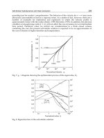
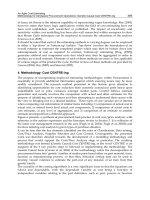
Fig. 11 shows the actuator assembly to rotate the pulley. To sustain the large torque around
the joint J
2,2
for the global finger flexion, it needs possibly larger reduction ratio. Therefore
a worm gear train, that generally has large gear ratio, is introduced, so that the entire
reduction ratio gets 1/1000. Although a worm gear train has no back-drivability, it is also an
advantage in this case because that gear train can support any large torque in case of
necessity. The movable range of the pulley is +15 to -15degree that makes useful adjusting
motion at the fingertip in 10mm order.
(a) Worm gear mechanism to drive the pulley (b) Actual embedded situation
Fig. 11. Differential mechanism for the independent root joint motion.
A Designing of Humanoid Robot Hands in Endoskeleton and Exoskeleton Styles 413
2.10 Smart Wiring for Bypassing Reducer
The quality of a robot system is evaluated from many kinds of dimension including
neatness of the electric wiring, since its weight and volume can bring recognizable
deterioration in the performance of high-speed motion and indisputably deteriorate the
appearance. The lack of space for containing the wiring is the most common cause of this
problem because expelling the wiring outside makes its weight and volume to increase. In
my robot hand, as mentioned in the section 2.4, the discussion about the designing root joint
structure of each finger was started by consideration of this problem. And more problem is
outstanding around the joint filled with the large reducer of ratio 1/350 meaning J
1,1
, J
1,2
,
J
1,4
, J
2,3
, J
3,3
, J
4,3
and J
5,3
. Recognizing the significance of this problem, a unique and
practical design of wiring is introduced.
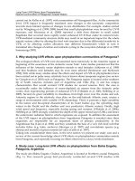
The role of the wiring is electric connection between the motor and sensor for the terminal
joint and the main PCB in the palm, and a thin flexible PCB with 3.5mm width makes it.
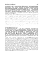
When the wiring is led as going around the reducer’s circular outline, the change of shortest
path length due to the finger flexion is remarkable, and then the method to retract and
extract the corresponding length of wiring becomes the practical problem. My robot hand,
fortunately, has enough margin space in the finger segments, and it can be formed an empty
space where the wiring can adapt to the change of path length with changing the curving
line by itself as shown in Fig. 12.
By the way, this wiring style cannot be adopted on the two thumb root joints J
1,1
and J
1,2
because of lack of the internal space, and then the wirings through these joints are forced to
go outside in a wide circle unbecomingly. This problem will be solved in the next
development step waiting for an investment opportunity.
(a) Change of wiring path due to the finger flexion (b) Flexible PCB
Fig. 12. Design of the wiring around the joint that contains the large reducer.
414 Humanoid Robots, New Developments
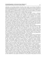
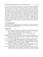
2.11 Overall view of the Humanoid Robot Hand
As a conclusion of all previous considerations the latest model of my robot hand is built up
as shown in Fig. 13; it has 15DOF as defined on the Table 2(b) while it satisfies the basic
design conditions on the Table 1. The total mass including the internal electric equipment
except the long cable connecting outside controllers is just 500g. The connections to outside
systems are only
φ
2.4 signal cable and
φ
4.5 power cable. Some dimensions of details like
the length of each finger segment are referred to my hand.
Fig. 13 Overall profile of the latest model.
A Designing of Humanoid Robot Hands in Endoskeleton and Exoskeleton Styles 415
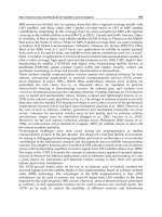
To confirm dexterity of the robot hand, some experiments of representative and practical
handling motions were conducted; this paper displays two handling types: pinching a
business card and holding a pen (Fig. 14). The key evaluation items in these experiments
were the two distinctive functions: the smooth compliance on a fingertip and the twisting of
the thumb. All the fingertip forces were generated by the simple open-loop torque control
method explained in the section 2.7 without force sensors.
By the way, the smart wiring style explained in the section 2.10 is installed only to the latest
model, and the robot hand used in the experiments did not have it unfortunately.
(a) Pinching a business card (b) Holding a pen
Fig. 14 The representative and practical handling motions.
In the experiment of pinching a business card, the robot hand performed switching several
times two couples of pinching fingers: the thumb and the index finder/the thumb and the
middle finger (Fig. 15). In the junction phase when all the three fingers contacted on the card,
the thumb slid its fingertip under the card from a position opposing a fingertip to another
position opposing another fingertip. In the experiment of holding a pen, the robot hand
moved the pen nib up and down and sled the thumb fingertip along the side of the pen (Fig.
16). In both experiments, the objects: card and pen were held stably, and these achievements
prove the contacting force appropriate in both strength and direction could be generated at
each fingertip.
Fig. 15 Cyclical steps in the experiment of pinching a business card.
416 Humanoid Robots, New Developments
Fig. 16 Cyclical steps in the experiment of holding a pen.
At the SIGGRAPH 2006, I got an opportunity to join into a participating party of the
“Hoshino K. laboratory in the university of Tsukuba” which introduced my humanoid robot
hand for the first time. The robot hand was demonstrated on a humanoid robot arm that is
actuated by pneumatic power, and has 7DOF wide movable range, slender structure and
dimensions like an endoskeleton of a human arm (Fig. 17). While its power is low and the
practical payload at the wrist joint is about 1kg, it could move the robot hand smoothly.
The conclusive advantage of the robot hand is that many complex functions are condensed
in the humanlike size, weight and appearance, and realize the sophisticated dexterity. As
the robot hand has rich suitability for delicate robot arms, after more sophistication, it will
be developed to a good prosthetic hand in the near future.
Fig. 17 Demonstration in the international exhibition SIGGRAPH 2006 in Boston.
A Designing of Humanoid Robot Hands in Endoskeleton and Exoskeleton Styles 417
3. Master Hand in Exoskeleton Style
3.1 Introduction of Circuitous Joint
As a dream-inspiring usage, the dexterous humanoid robot hand will be employed into
a super “magic hand” with which an operator can manipulate objects freely from far away
and get feedback of handling force and tactile sensations. Such intuitive master-slave control
method of a humanoid robot with feedback of multi-modal perceptions is widely known as
the Telexistence/Telepresence, however, developments of adequate master controllers for
them have been rare in comparison with slave humanoid robots. I guess one of major
reasons is a difficult restriction in mechanical design that any mechanism cannot interfere
operator’s body. To solve this problem an idea of exoskeleton is brought up by association
of a suit of armour that can follow wide movable range of human body with covering it.
The most popular and practical master hand in exoskeleton style is the CyberGrasp, and
most conventional master hands in exoskeleton style have the similar structure to it. They
are designed to be lighter and slenderer with less material, so they have no core structure
and cannot sustain their form as a hand without parasitism on operator’s hand. This means
they gives some constriction feeling to the operator and the slight force sensation in the
feedback is masked. Then I have tried to design an ideal exoskeleton that fulfils every of
lightness, slenderness and self-sustainability in its form.
In designing such exoskeleton, the main theme is focused on joint mechanisms. The most
practical joint is a revolute one that consists of an axis and bearings, and general ways to
place it corresponding to an operator’s joint are in parallel on backside or in coaxial beside.
However, the former tends to deteriorate the movable range of operator’s joint (Fig. 18(a))
and the latter cannot find an existing space between operator’s fingers. Therefore I propose
a novel joint mechanism named “circuitous joint” that has a virtual axis coincided with the
axis of operator’s skeleton while the all mechanism exists on backside of operator’s finger.
Technically this virtual axis is the instantaneous center of relative rotation of two segments.
Fig. 18(b) shows the principle of the circuitous joint that realizes the virtual axis by
stretching displacement s of two segments in proportion to the joint angular displacement
θ
.
Fig. 18 Behaviour of two types of revolute joint in following operator’s finger.
418 Humanoid Robots, New Developments
3.2 Fundamental Mechanism of the Circuitous Joint
In order to realize the principle of the circuitous joint mentioned above, rack and gearwheel
mechanism was adopted in consideration of high rigidity of structure, certainty of motion,
and facility of manufacturing. Fig. 19 shows the fundamental mechanism prepared for
a principle study. A gearwheel is rotated on a rack by relative rotation of two segments, and
shifting of its axis provides stretching of a segment that has the rack (Fig. 20). Since the two
segments should make same stretching displacement together, two sets of the mechanism
are combined in opposite direction. The gearwheel is formed to be sector gear by removing
unnecessary part. We may note, in passing, this mechanism is an “over-constrained”
mechanism, so it can keep its behaviour even without the actual axis.
Fig. 19 The fundamental mechanism as a unit of the circuitous joint.
Fig. 20 Mixed motion of rotating and stretching of two segments.
A Designing of Humanoid Robot Hands in Endoskeleton and Exoskeleton Styles 419
3.3 Kinematical Design of the Optimal Circuitous Joint
To make the virtual axis coincide exactly to the axis of operator’s skeleton, the relationship
between the angular displacement
θ
and the stretching displacement s must be non-linear.
This means the rectilinear rack and the circular gearwheels should not be adopted, however,
they can get practical use with optimal specifications calculated as follows.
Fig. 21 Kinematical symbols in the circuitous joint.
Fig. 21 shows definition of kinematical symbols of parts and parameters; for example, point
V is the virtual axis. The specifications that provide the shape of rack and sector gear are
only the pitch circle radius r of the sector gear and the standard offset p between the center-
lines of the Segment A and the Bone A. Since the standard offset p is decided 10mm due to
convenience of practical design of mechanism, only the radius r is an object to be optimised.
The point V moves on the Y-axis by change of
θ
and its behaviour is divided into three types
according to the size of r (Fig. 22). Considering its nearest trajectory to the point C, the
preferable range of r is presumed as 0.5p r (2/
π
)p.
Fig. 22 Motion of the virtual axis V on the Y-axis by change of
θ
.
The evaluation item for the optimisation was set a deviation d defined by next formula that
means deformation of kinematical relationship between two datum points A and B as
shown in the Fig. 21, and the optimal radius r should minimise it.
}sincos,sincos{where)(
22
θθθθθθθ
rpvrpruvpud +=−+−=−+=
(1)
Fig. 23 shows curves of the deviation d vs.
θ
in several settings of the radius r. The radius r is
set within the presumed range. To generalise the optimisation each parameter is dealt as
dimensionless number by dividing with the offset p. Screening many curves and seeking
a curve which peak of d during a movable range of
θ
is minimum among them, the optimal r
420 Humanoid Robots, New Developments
is found as the value that makes the sought curve. For example, when the movable range is
0
θ
π
/2 the optimal radius r is 0.593p and the peak deviation d is 0.095p, and when the
movable range is 0
θ
π
/3 the optimal radius r is 0.537p and the peak deviation d is 0.029p.
As the offset p is set 10mm, the peak of d is below acceptable 1mm; therefore, the mechanism
with rectilinear rack and circular gearwheels has practicability enough.
2/
/ = 0.5
π
d p
r p
/
θ
0.537
0.593
0.095
0.029
ππ
Fig. 23 Variation of curves of the deviation d.
3.4 Driving Method of the Circuitous Joint
To design the joint mechanism light and slender, a method to drive it from away via a wire
rope is introduced. The wire rope is set along two segments veering by a pulley on the
sector gear’s axis, and one end is fixed on a segment and another end is retracted/extracted
by a winding drum set at a stationary root (Fig. 24(a)). Since the wire rope can generate only
pulling force that rotates the joint in straightening direction, a spring is added to generate
pushing force that rotates it in bending direction (same (b)). This driving method has further
conveniences to be applied to a tandem connection model (same (c)). A wire rope to a distal
joint from the root can be extended easily through other joints. Its tensile force shares
accessorily a part of driving force of other joints they are nearer to the root and need
stronger driving force. Moreover, a coupled-driving method of plural joints can be realized
only by winding their wire ropes together with one drum. The rate of each rotation can be
assigned separately by independent radii on the drum.
(a) Path of the wire rope (b) Pushing spring (c) Tandem connection
Fig.24 Driving method of the circuitous joint.
A Designing of Humanoid Robot Hands in Endoskeleton and Exoskeleton Styles 421
r
p
: Radius of the pulley (constant)
k : Spring constant of the compression spring (constant)
Fs : Spring force generated by the spring (intermediate variable)
Fs’ : Spring force generated by the spring when
θ
= 0 (constant)
w : Retracting/extracting displacement of the wire rope (input variable)
F : Pulling force of the wire rope (input variable)
θ
: Joint angular displacement (output variable)
τ
: Joint torque (output variable)
Fig. 25 Statical symbols in the circuitous joint.
The definition of statical symbols is shown in Fig. 25, and the formulas for inverse statics
calculating the input (manipulated) variables: w and F, from the output (controlled)
variables:
θ
and
τ
are derived as follows.
θ
)(2 prrw += (2)
pp
2
p 2
s2
)2(2
2
2
1
rr
rF
rr
rk
rr
F
+
⋅
′
+
+
⋅
−
+
=
θτ
(3)
As these formulas show simple and linear relationship between the input and output
valuables, this driving method promises further advantage that the algorithm of controlling
both position and force is fairly simple. When the spring effect is negligible, as the second
and third terms on the right side of formula (3) are eliminated, we would be able to control
the output torque
τ
by using only the motor torque as the controlled variable.
3.5 Master Finger Mechanism (MAF)
Fig. 26 shows the practical master finger mechanism (MAF hereafter) corresponding to
a middle finger of my hand and my humanoid robot hand, and proves the mechanism can
follow them in wide movable range from opening to clenching. MAF is constructed with
three discrete joint units, so that they are connected adapting to various pitch of operator’s
finger joints (Fig. 27). To make MAF narrow and short enough, each unit is designed
possibly thin and aligned with partly overlapping. In this instance, all joints are coupled-
driven by one relatively large motor (Faulhaber, model 1724SR).
As shown in Fig. 28, the actual rack is placed in opposite side viewed from the axis in
comparison with the previous illustrations. The reason is to dissolve the interference
between the mechanism and operator’s finger that has came up in the previous
arrangements. Inverse gear is added to correct the stretching direction of each segment and
carried on a slider to keep the position at midpoint of the rack and the sector gear.
422 Humanoid Robots, New Developments
Fig. 26 Master finger mechanism (MAF) following various finger flexions.
Fig. 27 Adjustable tandem connection of three joint units.
Fig. 28 Internal mechanism of the joint unit.
A Designing of Humanoid Robot Hands in Endoskeleton and Exoskeleton Styles 423
3.6 Master-Slave Control with Encounter-Type Force Feedback
As an ideal scheme of force display to the operator, the “encounter-type” has been proposed
(McNeely, 1993, Tachi et al., 1994); that means a small object held up by a robot arm is
approached and pressed to a part of operator’s body where tactile sensation is necessary as
occasion demands. Its chief advantages are making the operator to discriminate clearly the
two phases “non-contact” and “contact”, and free from constriction feeling during the non-
contact phase. As it is suitable for the feature of my desired master hand, MAF introduced a
function of non-contact following to the operator’s finger.
Since the present MAF has only 1DOF, the target motion of operator’s finger is reduced to
same 1DOF, and a gap between both fingertips of MAF and the operator is set as the
controlled variable during the non-contact phase. Concretely, a sensor at fingertip of MAF
measures the gap, and MAF is position-controlled to keep the gap at the desired value 2mm.
Fig. 29 shows the fingertip assembly that contains a micro optical displacement sensor
(Sanyo Electric, SPI-315-34), technically that detects motion of a swing reflector moved by
the operator’s nail in slight force, and the gap is presumed from the motion.
During the contact phase, on the other hand, MAF should generate a desired contacting
force against the operator’s fingertips at the contact tip of the fingertip assembly. So a film-
like force sensor (Nitta, FlexiForce) on the contact tip measures the contacting force, and
MAF is force-controlled by changing the motor torque of winding the rope in proportion to
the difference between the measured and desired contacting forces.
An experimental master-slave system between MAF and a slave humanoid robot finger
(SLF hereafter) was constructed as follows. SLF is always position-controlled to realize the
same motion of MAF. The two phases of contact/on-contact on controlling MAF are
switched according to detecting existence/non-existence of the contacting force on SLF.
A film-like force sensor on the surface of SLF’s fingertip measures the contacting force, and
the desired contacting force that MAF should generate is given as equal to that of SLF.
Fig. 29 Fingertip assembly for the master finger mechanism (MAF).
In order to confirm practicability of the master-slave system, an experiment was conducted.
Fig. 30 shows the coupled motion of MAF and SLF in the non-contact phase; MAF was
following the operator’s finger with keeping a small gap at the fingertips. MAF and SLF
could follow the operator’s finger exactly as high as a less drastic speed. Since MAF had
only 1DOF, SLF was prepared as the 1DOF mechanism interlocked all three joints. Moreover,
the operator should also make his/her finger motion interlocking the three joints roughly
similar to the behaviour of MAF. Though, I could forget an uncomfortable feeling by the
fixed behaviour after familiarization, and enjoyed this experience.
424 Humanoid Robots, New Developments
Fig. 30 Circumstance of the experimental master-slave control.
Master (MAF)
Slave (SLF)
Time [s]
Contacting Force [N]
Contact Phase
Tip Gap [mm]
˥
˥
˥
˭
Fig. 31 Experimental result of transferring the contacting force.
Fig. 31 shows an experimental result;
θ
1
+
θ
2
+
θ
3
means the sum of three joint angular
displacements on MAF. The two vital features are shown: prompt switching of contact/non-
contact phases, and transferring the contacting force from SLF to MAF. The contacting force
at the fingertip of SLF was given by an assistant pushing on it; for example, the two contact
phases at the time 7s and 10s were caused by assistant’s tapping. While the algorithm
switching the phases was a primitive bang-bang control, an oscillation iterating contact/
non-contact did not occur. I guess the season: since the gap between the fingertips is kept
small during the non-contact phase, the impact at the encounter that will lead the oscillation
is not so serious, moreover the human fingertip has effective damping to absorb it.
As shown by the curves after the time was 13s, the operator’s finger could be moved by the
assistant’s force; the master-slave (bilateral) control with force feedback was verified.
In conclusion of this experiment, MSF has enough performance as a principal part of the
master hand for the Telexistence/Telepresence.
A Designing of Humanoid Robot Hands in Endoskeleton and Exoskeleton Styles 425
3.7 Overall view of the Master Hand
Since it comes to the end of width of this paper, I describe briefly the overall view of the
master hand. By the way, the nomenclature of each joint is same as shown in the Fig. 1.
I gave four fingers to the master hand (Fig. 32); the little finger was omitted due to its little
worth in general activities. The three finger mechanisms are same as shown in the Fig. 26,
and the second and fourth finger have the abduction-adduction motion with active joints at
J
2,1
and J
4,1
. The each joint is position-controlled to follow lateral motion of the operator’s
finger detected at fingertip with similar sensor mechanism as shown in the Fig. 29; however,
the additional sensor put beside the fingertip is omitted in the Fig. 32.
In the thumb mechanism, the distal three segments are constructed with two circuitous
joints at
J
1,4
and J
1.5
. At the same time, elated ingenuity is exercised to design the joint
mechanism corresponding to the carpo-metacarpal (CM) joint of operator; to make the two
joint axes
J
1,1
and J
1.2
intersected in an empty space for containing the CM joint, a slider
mechanism is introduced where a motor-driven carriage runs on a sector rail in a wide circle.
While the two joint axes
J
1,3
and J
1.4
for the MP joint are not intersected, the order of each
direction of joint axis and fingertip is identical to that of the Shadow hand (Fig. 2).
In the non-contact phase, the thumb mechanism is position-controlled to follow the
operator’s thumb opposing on both fingertips; each independent DOF has individual sensor
similar to the previous one. As the mechanism does not touch the operator’s thumb, slight
deviation of the controlling is negligible. In the contact phase, only the joints
J
1,4
and J
1.5
are
switched its control mode to the force-control. More sophisticated control algorithm for this
thumb mechanism is under study in the “Tachi S. laboratory of the university of Tokyo”
where I started developing this master hand as a researcher in 2001.
Fig. 32 Whole picture of the master hand.
426 Humanoid Robots, New Developments
4. Conclusion
To contribute on the evaluative process of searching the appropriate designing paradigms as
a mechanical engineer, I bring up in this paper some of my ideas about the robot hand
design concretely. While the designs of my robot hands may seem to be filled with eccentric,
vagarious and serendipitous ideas for some people, I believe they are practical outcomes of
flexible ingenuity in mechanical designing, so that they can take on pre-programmed but
robust actuating roles for helping the programmable but limited actuators, and realize
higher total balance in mechatronics. At the same time, for examining their practicability,
reasonability and inevitability through the eyes of many persons, it will need to establish
a standard definition and evaluation items in kinematics, dynamics, control algorithms and
so on, that can subsume almost all humanoid robots. Concretely, a standard formats would
be prepared to sort and identify any robot system by filling it. The Fig. 1 and 2 show my
small trial of comprehensive comparison under a standard definition in the robot hand
kinematics. And I hope the worldwide collaboration, so that it will promote developments
of many sophisticated mechanical and electric elements that are easy to be used by many
engineers like me who want any help to concentrate on his/her special fields.
5. Reference
CyberGrasp: Immersion Co.
DLR Hand: German Aerospace Center
Gifu Hand: Dainichi Co., Ltd.
Harada Hand: Harada Electric Industry Inc.
Jacobsen, S.C. et al. (1984). The UTAH/M.I.T Dextrous Hand: Works in Progress, Int. J. of
Robotics Research, Vol.3, No.4 (1984), pp.21-50
Lovchik, C.S. & Diftler, M.A.(1999). The Robonaut Hand: A Dexterous Robot Hand For
Space, Proc. of IEEE Int. Conf. on Robots & Automation, Detroit, MI, May 1999
McNeely, W.A. (1993). Robotic Graphics: A New Approach to Force Feedback for Virtual
Reality, Proc. of IEEE Virtual Reality Annual Int. Symp., pp.336–341, Seattle, Sep 1993
NASA Hans: National Aeronautics and Space Administration
Shadow Hand: Shadow Robot Company Ltd.
Tachi, S. et al. (1994). A Construction Method of Virtual Haptic Space, Proc. of the 4th Int.
Conf. on Artificial Reality and Telexistence (ICAT '94), pp. 131-138, Tokyo, Jul 1994
Teleistence: Tachi, S. et al., Tele-existence (I): Design and evaluation of a visual display with
sensation of presence, Proc. of the RoManSy ‘84, pp. 245-254, Udine, Italy, Jun 1984
Telepresence: Minsky, M., TELEPRESENCE, OMNI, pp. 44-52, Jun 1980
Weghel, M.V. et al. (2004). The ACT Hand : Design of the Skeletal Structure, Proc. of IEEE Int.
Conf. on Robots & Automation, pp. 3375-3379, New Orleans, LA, Apr 2004
24
Assessment of the Impressions of Robot Bodily
Expressions using Electroencephalogram
Measurement of Brain Activity
A. Khiat
1
, M. Toyota
2
, Y. Matsumoto & T. Ogasawara
Nara Institute of Science and Technology – NAIST
JAPAN
1. Introduction
Recently, robotics research has focused on issues surrounding the interaction modalities
with robots, how these robots should look like and how their behavior should adapt while
interacting with humans. It is believed that in the near future robots will be more prevalent
around us. Thus it is important to understand accurately our reactions and dispositions
toward robots in different circumstances (Nomura et al., 2006). Moreover, the robot’s correct
production and perception of social cues is also important. Humans have developed
advanced skills in interpreting the intentions and the bodily expressions of other human
beings. If similar skills can be acquired by robots, it would allow them to generate behaviors
that are familiar to us and thus increase their chances of being accepted as partners in our
daily lives.
The expressiveness of a gesture is of great importance during an interaction process. We are
often required to give special attention to these signs in order to keep track of the interaction.
Humans have learned to adapt their behavior and to react to positive and negative bodily
expressions (Bartenieff & Lewis, 1980). Although there has been remarkable work on the
design issues of sociable robots (Breazeal, 2002) and affective autonomous machines
(Norman et al., 2003), there has not been much work on investigating the real impact of
robot bodily expressions on the human user in the context of human-robot interaction.
Knowing the effect of a generated gesture, a robot can select more accurately the most
appropriate action to take in a given situation. Besides, computer-animated characters have
been used to evaluate human perception of the significance of gestures. However, animated
characters and embodied ones should be treated differently since the latter are tangible
entities (Shinozawa et al., 2005).
In this article we report a study on the relation between bodily expressions and their
impacts on the observer. We also attempt to understand the effect that expressions have on
the observer’s brain activity. Its sensitivity to bodily expressions can be used during an
interaction task since the brain is the source of every cognitive and emotional effort.
1
Corresponding author: ABDELAZIZ KHIAT, Robotics laboratory, Graduate School of Information Science, Nara Institute of
Science and Technology, Keihanna Science City, 630-0192 JAPAN. Email:
2
MASATAKA TOYOTA is currently with Canon Corporation.
428 Humanoid Robots, New Developments
Fig. 1. Considered scenario for robot bodily expressions and its perceived impression.
In this work, we have conducted an experimental study where several users were asked to
observe different robot bodily expressions while their brain activity was recorded. The
results suggest the existence of a relation between the type of bodily expressions and the
change in the level of low-alpha channel of brain activity. This result helped in the selection
of features that were used to recognize the type of bodily expression an observer is watching
at a certain time. The recognition rate was of about 80% for both cases of robot bodily
expressions and of human bodily expressions. Potential applications include customized
interface adaptation to the user, interface evaluation, or simple user monitoring.
2. Bodily expressions and their impressions
The considered scenario for this study is depicted in Fig. 1. First, we have a robot that is
executing a series of movements. It transmits to the observer a meaningful expression which
is called bodily expression
c
. Second, we have a human observer that perceives the
expression and interprets it using his/her a priori knowledge
d
. Then, the observer gets an
impression, which means that bodily expression affects him/her to a certain level,
depending on its strength, his/her awareness or attention and his/her state of mind or
mentality
e
. It is important to emphasize the difference between how the observer
perceives and interprets a bodily expression, and what impact this expression evokes in the
observer. It is expected that the two are related, but there is no information about the nature
of this relation or how it evolves and changes over time. One of the goals of this work is to
clarify and explain certain aspects of this relation to open the possibility of generating an
adaptive robot behavior based on this information.
Fig. 2. The subset of Shaver's classification of emotions used in the categorization of Bodily
Expressions.
Assessment of the Impressions of Robot Bodily Expressions using
Electroencephalogram Measurement of Brain Activity 429
2.1 Classification of bodily expressions
There is a need to classify bodily expressions generated by a robot in order to investigate
their effects on the user. For this reason, salient differences among motions should be
implemented. During an interaction process, humans go through different affective states,
depending on several conditions such as degree of engagement, degree of awareness, and
degree of interest among others. It is thus possible to classify every action taking place
during an interaction process into the emotional effects that it would have on the observer.
We adopted a simplified version of Whissel’s wheel of activation-evaluation space described
in (Whissel, 1989). We used the fact that we have two primary states for emotions: positive
and negative ones, also known as pleasant and unpleasant emotions. The considered
emotions are the following: happiness, surprise, sadness, and anger. In order to categorize
these emotions we used a subset of Shaver’s classification (see Figure 2), where happiness
and surprise represent pleasant emotions while sadness and anger represent unpleasant
emotions (Shaver et al., 1987). Bodily expressions were classified using one of the specified
four emotions as pleasant or unpleasant.
2.2 Generation of robot bodily expressions
The humanoid robot ASKA (Ido et al., 2002) used in this study is shown in Figure 3. The
body has a mobile platform and two arms and is based on the commercial robot TMSUK-4
3
.
The head is a replica of the Infanoid robot (Kozima, 2002). This humanoid robot with its
mobile platform has the advantage of being able to generate relatively fast motions
compared to the currently available biped humanoid robots.
Since the pioneering work of (Johansson, 1973) on visual perception of biological motion, it
has been known that humans can perceive a lot of information from body movements
including the emotional state of the performer (Allison et al., 2000; Pollick et al., 2001).
Recently, there is a growing interest in mathematically modeling emotion-based motion
generation for real-world agents such as robots (Lim et al., 2004) and for virtual agents such
as animated characters (Amaya et al., 1996). To be able to generate bodily expressions that
reflect the selected emotions we rely on Laban features of movements (Bartenieff & Lewis,
1980). It has been shown by (Tanaka et al., 2001) that the qualitative Laban features of Effort
and Shape correlate with the four basic emotions we have selected in section 2.1.
Based on the mathematical description of Laban features, shown in the Appendix, it is
relatively easy to classify bodily expressions that reflect a certain emotion. Although there is
no unique solution to this problem, the goal is to be able to generate a representative bodily
expression for each one of the selected emotions.
The generated bodily expressions (BE) which reflect one of the basic emotions of happiness,
surprise, sadness, anger or none are the following:
• BE1: The robot raises both arms and turns its body to the left, then to the right,
twice. The goal is to show an expression of happiness.
• BE2: The robot raises its right hand and moves it in an arc toward the right side,
then goes back to its initial position and lowers its right arm, the goal is to show an
expression of no particular emotion.
• BE3: The robot raises both arms and its head, then moves backward for some
distance, the goal is to show an expression of amazement or surprise.
3
TMSUK-4 is a trademark of tmsuk Co. Ltd, Kitakyushu.
430 Humanoid Robots, New Developments
• BE4: The robot lowers both arms and its head, then moves backward at low speed
for some distance, the goal is to show an expression of sadness.
• BE5: The robot raises both arms gradually while advancing before stopping, then it
lowers and raises its arms progressively for two cycles; the goal is to show an
expression of happiness.
• BE6: The robot advances quickly, then goes back and raises its right arm while
turning its head a bit to the right. It then lowers its arm and returns its head to the
original position; the goal is to show an expression of anger.
Fig. 3. Overview of the receptionist robot ASKA and its joints-link model.
The duration of each of these BEs was about 14[sec]. Their appropriateness and their
expressiveness was tested experimentally using questionnaires (see section 3.1).
2.3 Assessment of impression and expressiveness of bodily expressions
There are mainly two types of methods to assess the effects of a particular action on a
human. The classic self-reporting approach is widely used, while the assessment from
measured physiological information is still an open research problem. The first type of
methods gives subjective evaluation results; whereas the second type of methods is deemed
to be more objective but suffers from inaccuracies. For our case, in order to assess
expressiveness we adopted a self-reporting approach and asked the subjects to answer
questionnaires. However, in order to assess impression the subjects answered
questionnaires and their brain activity was also recorded.
Summarizing the subject’s answers to questionnaires was used in order to assess
expressiveness. Every subject had to select from: expression of happiness, expression of
surprise, expression of sadness, expression of anger, or no meaningful expression. The
subject also had to specify the degree of the expression in a scale of five: 1 for impertinent, 2
for slight, 3 for medium, 4 for strong and 5 for very strong. This selection of the degree of
expression is a redundancy that was meant to confirm the subject’s choice and assess the
degree of confidence in his/her answer. These answers were then categorized into pleasant
or unpleasant expressions using the subset of Shaver’s classification shown in Figure 2.
Assessment of the Impressions of Robot Bodily Expressions using
Electroencephalogram Measurement of Brain Activity 431
As for impression assessment, spectral analysis method of electroencephalogram (EEG) data
was used. A short EEG segment can be considered as a stationary process, which can be
characterized by an autoregressive (AR) model. Let us denote
)(ns as a sample of EEG
data of
N points. We calculate
)(nr
f
and )(nr
b
, respectively the forward and backward
prediction errors, as follows:
() ()( )
¦
=
−+=
p
k
f
kpnskanr
0
(1)
() ()( )
¦
=
+=
p
k
b
knskanr
0
(2)
where
)(ka is the AR parameters and
p
is the order of the model. The order
p
is based
on the “goodness of fit” criterion. We use the relative error variance (REV) criterion (Schlögl
et al., 2000), defined as:
()
()
MSY
pMSE
pREV =
(3)
)( pMSE is the mean square error or variance of the error process of order
p
, and
MSY
is the variance of the total power of the signal sample. The optimal
p
is the one that
minimizes
)( pREV . In our case we take 14=p .
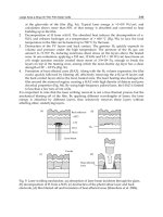
Fig. 4. An example illustrating the calculation of the power of low-alpha band for a
2[sec] data segment taken from electrode placement F3. The graph to the left shows the
raw EEG signal for the baseline period and the observation period. The graph to the
right shows the power spectra of the EEG signals, where low-alpha frequency band is
highlighted.
We apply (1) and (2) to calculate an approximate estimation of the power spectrum
)( fPS
of the signal s as follows:
432 Humanoid Robots, New Developments
()
()
2
0
2
1
¦
=
−
+
=
p
k
fkTj
p
eka
TV
fPS
π
(4)
()
[]
()
[]
()
¦
−+
=
+=
1
0
22
2
1
pN
n
bfp
nrnrV
, (5)
where
p
V
is the averaged sum of the forward and backward prediction error energies and T
is the sampling period.
Research in cognitive neuroscience has shown that the power of low-alpha frequency band
is the most reactive band to social cues such as movements (Allison et al., 2000; Cochin et al.,
1998). We suppose that this frequency band reacts in a similar way to robot bodily
expressions (Khiat et al., 2006). The next step in assessing the impression is to observe the
amount of change in the power of low-alpha frequency band compared to the whole
spectrum. The power
L
of a band between frequencies a and b is defined by:
()
()
³
³
∞
=
0
)(
,
dffPS
fdfPS
baL
b
a
(6)
Using (6), we calculate the power of low-alpha band frequency
b
L for the data taken during
the baseline period and
m
L for the data taken during the period of the execution of a bodily
expression. An example illustrating this calculation is shown in Fig. , where raw 2 seconds
EEG signals collected during the baseline period and the observation period is shown to the
left. The power spectrum of these signals is shown to the right, and the low-alpha frequency
band is highlighted. A comparison between
b
L and
m
L would indicate the effect of a
particular bodily expression on the user. This is used as the main evaluation criterion for
impression.
3 Experimental study
3.1 Expressiveness of robot bodily expressions
The goal of this experiment is to evaluate the expressiveness of every generated robot bodily
expression. Since this quality is highly subjective, the self-reporting approach is used.
Subjects. Seventeen (17) participants (two females and fifteen males aged between 20 and 50
years old) volunteered to take part in this experiment. They were either students or faculty
members at the Graduate School of Information Science. They were all familiar with robots
and had previous experiences of dealing with robots similar to the one used in the experiment.
Procedure. Every subject was shown a total of six bodily expressions, which were described
in section 2.2. The execution of each of the bodily expressions by the humanoid robot ASKA
lasted 14 seconds. After observing each robot bodily expression, enough time was given to
the subject to answer two questions about the expressiveness of that robot bodily expression,
and one more question about their impression after the observation. These answers were
then summarized as explained in section 2.3 to assess their expressiveness.
Assessment of the Impressions of Robot Bodily Expressions using
Electroencephalogram Measurement of Brain Activity 433
BEs Pleasant Unpleasant Neither
BE1 100% 0% 0%
BE2 6% 35% 59%
BE3 94% 6% 0%
BE4 0% 94% 0%
BE5 65% 12% 23%
BE6 0% 82% 18%
Table 1. Users’ evaluations of the expression of each generated robot bodily expression (BE).
Results. Table 1 shows the results about bodily expressions after categorization into
pleasant expressions, unpleasant expressions, or neither, clearly indicating the
expressiveness as evaluated by the observers. The result about impressions is presented in
Table 2 after categorizing the answers into pleased or unpleased.
These results demonstrate the existence of a strong correlation between the expressiveness
of the robot bodily expressions as seen by the subjects and the target expression when these
bodily expressions were generated (see section 2.2). BE1, which was created to express
happiness, was classified as having a 100% pleasant expression. BE2, which was created to
express a neutral emotion, was classified by 59% as neither pleasant nor unpleasant, and by
35% as unpleasant, suggesting that neutral bodily expressions can have a negative
connotation. BE3, which was created to express surprise, was classified by 94% as a pleasant
expression. BE4, which was generated to express sadness, was classified by 94% as being an
unpleasant expression. Similarly, BE6 which was created to express anger was also classified
by 82% as an unpleasant expression. The special case of BE5 was classified to a great extent
as a pleasant expression by up to 65%. However, 23% said it did not express anything in
particular and 12% claimed it was unpleasant.
BEs Pleased Unpleased Neither
BE1 65% 35% 0%
BE2 30% 70% 0%
BE3 68% 32% 0%
BE4 19% 81% 0%
BE5 100% 0% 0%
BE6 47% 53% 0%
Table 2. Users’ evaluations of their impressions after observing each robot bodily expression
(BE).
The expressiveness of the generated BEs is confirmed to be in accordance with the target
expressions for which they were created. BEs generated to express happiness and surprise
expressions were classified as pleasant, and the BEs generated to express sadness and anger
expressions were classified as unpleasant. Among the generated BEs we could choose one
that is representative of each category in order to use it in the evaluation of its impressions
on the observer.
434 Humanoid Robots, New Developments
3.2 Impressions of robot bodily expressions
The goal of this experiment is to evaluate the impression on the observer of the generated
bodily expressions using a hybrid approach that combines the results of self-reporting and
the analysis of brain activity.
Subjects. Seven (7) participants (one female and six males, 23∼43 years old) volunteered to
take part in this experiment. They were all students or faculty members at the Graduate
School of Information Science, and only two of them had the experience of using
electroencephalography to measure brain activity. Before starting the experiment each
participant was fitted with electrodes and allowed to spend more than 20 minutes reading
books of interest to familiarize and condition them to the electrodes’ presence.
Procedure. During each session, 12 EEG channels (using sintered Ag/AgCl electrodes) were
recorded by the 5200 Series DigitalAmp System
4
. The recording was performed from 10
placements, namely: Fp1, Fp2, F3, F4, T3, T4, P3, P4, O1, and O2 according to the international
10-20 standard (see Fig. 5). The placement Fz was used as the ground, and the signal from the
left ear placement A1 was used as the reference signal. The contact impedance between all
electrodes and the skull was kept below 5[kΩ]. The subjects were shown a total of six motions
lasting 14 seconds each by the humanoid robot ASKA while their brain activity was recorded
with 16-bit quantization at a sampling frequency of 200[Hz].
Fig. 5. The experimental setup where brain activity was measured according to the 10-20
international standard (Jasper, 1958).
The subjects were asked to relax as much as possible and think of nothing in particular
when recording the baseline period, which lasted for 14[sec]. They were also told that they
would be asked about the robot’s movements and that they had to watch carefully when the
robot was moving. This was important because we needed to make sure that the subjects
attended to the task. After the observation of each bodily expression, the subjects described
4
The 5200 Series DigitalAmp System is a trademark of NF Corporation, Yokohama.
Assessment of the Impressions of Robot Bodily Expressions using
Electroencephalogram Measurement of Brain Activity 435
their impression in their own words. Having no constraints to express themselves, the
subjects gave more details about their impressions. These answers were used in categorizing
the impressions into pleased or unpleased based on Shaver’s original classification of
emotions (Shaver et al., 1987).
Results. Table 2 shows the self-reporting result about the subjects’ impressions after
observing every robot bodily expression. There is a strong correlation between these results
and the expression results, reported previously in section 3.1, with a coincidence level of
71%. For example, BE4 impression was considered to be unpleasant by up to 81% and its
expressiveness was considered unpleasant by 94%. This is also the case for BE1 where its
impression of being pleasant is 65%, and it expression of being pleasant is 100%. The same
could be said for BE3, with a pleasant impression of 68% and a pleasant expression of 94%.
The case of BE6 is different from the previous ones. While its expression was considered
unpleasant by 82%, its impression shows the small rate of 53% for being unpleasant and
47% for being pleasant. It is still inclined to the unpleasant side. However, its pleasant effect
cannot be explained knowing that this bodily expression was created to express anger. The
last case of BE2 shows a big difference between its 59% neutral expression and its 70%
unpleasant impression.
Electrodes
Subject Category
Fp1 Fp2 F3 F4 T3 T4 P3 P4 O1 O2
Pleasant – – –
+
– – – –
+
–
1
Unpleasant –
+
–
+ +
– – –
+
–
Pleasant – –
+
– – – – – – –
2
Unpleasant – – – – – –
+ +
– –
Pleasant – – – –
+ +
–
+
– –
3
Unpleasant – – – – – – – – – –
Pleasant – – – – –
+ + +
– –
4
Unpleasant – – – – – –
+ + +
–
Pleasant – – – – –
+
– – – –
5
Unpleasant – – – –
+ + + +
– –
Pleasant
+ +
– –
+ +
– – – –
6
Unpleasant – – – –
+ +
– – – –
Pleasant – –
+
–
+ +
– – –
+
7
Unpleasant – –
+
– – – –
+
– –
Table 3. Significant change in low-alpha power according to observed motion categories at
every electrode and for each subject. (+: significant change p<.05; –: no significant change).
This suggests that bodily expressions with a neutral expression can be perceived negatively
and can generate an unpleasant impression. The analysis of EEG data using the method
described in section 2.3 allowed the calculation of the power
m
L
of low-alpha frequency
band in each electrode channel and for each bodily expression. It also allowed the
calculation of the power
b
L
of the same frequency band for the baseline period. Comparing
m
L
and
b
L
revealed the effect of observing a bodily expression in the change in the power of
low-alpha frequency band for each electrode channel. Table 3 summarizes the results of this
change in power, where only statistically significant change is indicated with the symbol +.
436 Humanoid Robots, New Developments
It can be seen that significant effect is mostly present at locations T3 and T4, then at P3 and
P4, and finally at F3 and F4. Knowing that these positions are located above the superior
temporal sulcus (STS) and above some specific parts of the prefrontal cortex (PFC) confirms
previous research findings about the activation of STS in the perception of social cues
(Cochin et al., 1998; Allison et al., 2000), and the activation of the mirror neurons located in
the PFC during learning and imitation tasks (Rizolatti & Craighero, 2004). Some reaction can
also be seen at other locations, for instance O1 and Fp2 for subject 1, O2 for subject 7, Fp1
and Fp2 for subject 6. The reaction at locations Fp1 and Fp2 are thought to be the result of
blinking activity during the recording process, since these electrode positions are the closest
to the eyes. It is important to assert that no preprocessing was done to avoid data with eye
blinking artifacts. This approach was adopted because the goal is to conduct this
investigation in natural conditions, where blinking activity is possible and should be
considered. The reaction at locations O1 and O2 could be explained by the fact that during
the vision process the visual cortex gets activated and this activation is usually captured at
locations O1 and O2.
Nevertheless, the reactive locations were not always the same among different observers,
suggesting high individual differences. A generalization cannot be derived at this point
about the reaction of brain locations according to the category of the bodily expression that
is being observed. However, the presence of a reaction is confirmed and another approach is
necessary to achieve a more comprehensive result. On the other hand, there is a need to
assess the repeatability of similar reactions from the same observer when he/she is shown
the same bodily expression.
3.3 Repeatability of reaction in brain activity
The goal of this experiment is to confirm that the results obtained in the impression
experiment (see section 3.2) are consistent over time for the same person. In other words, to
make sure that brain reaction does happen all the time and at the same set of electrodes if a
subject observes the same bodily expression several times.
Subject. One (1) student (male, 32 years old) volunteered to take part in this experiment.
Similar to the previous experiment, the subject was fitted with an electro-cap and was given
about 30 minutes to familiarize and get used to the presence of the cap.
Procedure. The subject participated in ten recording sessions. In each session, he was shown
two bodily expressions, one for each category of bodily expressions, executed by the
humanoid robot ASKA. Showing only representative bodily expressions is sufficient since
the goal is to confirm the repeatability of brain reaction. Each bodily expression lasted for
14[sec], and the baseline period was recorded during the 14[sec] before the execution of
each bodily expression. BE1 was chosen as a representative of pleasant bodily expressions,
and BE4 was chosen as a representative of unpleasant bodily expressions. On one hand,
BE1 was chosen because its expressiveness evaluation as pleasant (100%) was the highest
among all the bodily expressions. Its impression evaluation (65%) was high enough to
make sure it will have the desired effect on the observer, even though its impression was
evaluated as the lowest among all the pleasant bodily expressions. In this case, the
advantage was given to the expressiveness evaluation over the impression evaluation. On
the other hand, BE4 was chosen because, similarly to BE1, its expressiveness evaluation as
unpleasant (94%) was the highest among all the bodily expressions. Its impression
evaluation (81%) was also the highest among all the bodily expressions, making it the