Engineering Materials vol 1 Part 12 ppt
Bạn đang xem bản rút gọn của tài liệu. Xem và tải ngay bản đầy đủ của tài liệu tại đây (1.21 MB, 25 trang )
Materials and
energy
in
car design
267
densities) but only
:2
(the ratio of their
p/E%)
because the aluminium panel has to be
thicker to compensate for its lower
E.
High strength steel
does
offer a weight saving for strength-limited components:
bumpers, front and rear header panels, engine mounts, bulkheads, and
so
forth; the
weight saving
(p/cr$)
is
a factor of 1.5. Both aluminium alloy and fibreglass offer
potential weight savings of up to
3
times
(p/cr$)
on these components. This makes
possible
a
saving of at least
30%
on the weight of the vehicle;
if,
in addition, an
aluminium engine block
is
used, the overall weight saving
is
larger still. These are very
substantial savings
-
sufficient to achieve the increase in mileage per gallon from
22.5
to
34.5
without any decrease in the size of the car, or increase in engine efficiency.
So
they are
~bviouslgi
worth examining more closely. What, then, of the
other
properties
required of the substitute matgials?
Althcaugh resistance to deflection and plastic yielding are obviously
of
first im
tance
in
choosing
allternative materials, other properties enter into the selection. &et
us look at these briefly. Table 27.4 lists the conditions imposed by the service
environment.
Table
27.4
The service environment
of
he average car
Loadinlg
?hysiccd
environment
Chemical environment
Static
+
Elastic
or
plastic deflection
Impact
+
Elastic or plastic deflection
Impact
+
Fracture
Fatigue
+
Fatigue fracture
Long-term static
+
Creep
-40°C
<
J
<
120°C
55%
<
relative humidiiy
<
100%
Water
Oil
Brake fluid
Transmission fluid
Petrol
Antifreeze
Salt
Consider these
in
turn.
Elastic
and
plastic
deflection we have dealt with already. The
toughness of steel is
so
high that
fracture
of
a steel panel
is
seldom a problem. But what
about the other materials? The data for toughness are given in Table 27.5.
But what
is
the proper way to use toughness values? The most sensible thing to do
is
ask: suppose the panel
is
loaded up to its yield load (above this load we
know
it
will
begin to fail
-
by plastic flow
-
so
it
does not matter whether other failure mechanisms
also appear); what is the maximum crack size that
is
still stable? If this
is
large enough
268 Engineering Materials
1
Table
27.5
Properties
of
body-panel materials: toughness, fatigue and creep
Material Toughness Tolerable Fatigue Creep
G,
[kJm-’)
crack length
[mml
OK
OK
I
OK
Mild
steel
=loo
=1
A0
High-strength steel
=loo
=26
Aluminium alloy
=20
=12
OK
GFRP
(chopped fibre, moulding grade)
=37 =30
OK
Creep above 60°C
that it should not appear in service, we are satisfied; if not, we must increase the
section. This crack size is given (Chapter 13) by
from which
EGC
%lax
=
Tu;
The resulting crack lengths are given in Table 27.5 A panel with a crack longer than this
will fail by ’tearing’; one with a short crack will simply fail by general yield, i.e. it will
bend permanently. Although the tolerable crack lengths are shorter in replacement
materials than in steel, they are still large enough to permit the replacement materials
to be used.
Fatigue
(Chapter
15)
is always a potential problem with any structure subject to
varying loads: anything from the loading due to closing the door to that caused by
engine vibration can, potentially, lead to failure. The fatigue strength of all these
materials is adequate.
Cveep
(Chapter 17) is not normally a problem a designer considers when designing a
car body with metals: the maximum service temperature reached is 120°C (panels near
the engine, under extreme conditions), and neither steel nor aluminium alloys creep
significantly at these temperatures. But
GFRP
does. Above 60°C creep-rates are
significant.
GFRP
shows a classic three-stage creep curve, ending in failure;
so
that
extra reinforcement or heavier sections will be necessary where temperatures exceed
this value.
More important than either creep or fatigue in current car design is the
effect
of
environment
(Chapter 23). An appreciable part
of
the cost of a new car is contributed by
the manufacturing processes designed to prevent rusting; and these processes only
partly work
-
it is body-rust that ultimately kills a car, since the mechanical parts
(engine, etc.) can be replaced quite easily, as often as you like.
Steel is particularly bad in this regard. In ordinary circumstances, aluminium
is
much
better as we showed in the chapters on corrosion. Although the effect of salt on
aluminium is bad, heavy anodising will slow down even that form of attack to tolerable
Materials and energy in car design
269
levels (the masts of modern yachts are made of anodised aluminium alloy, for
example).
So
aluminium alloy is good: it resists all the fluids likely to come in contact with it.
What about GFRP? The strength of GFRP is reduced by up to
20%
by continuous
immersion in most of the fluids
-
even salt water
-
with which it is likely to come into
contact; but (as we know from fibreglass boats) this drop in strength is not critical, and
it occurs without visible corrosion, or loss of section. In fact, GFRP is much more
corrosion-resistant, in the normal sense of 'loss-of-section', than steel.
Production methods
The biggest penalty one has to pay in switching materials is likely to be the higher
material and production costs.
High-strength steel,
of course, presents almost no
problem. The yield strength is higher, but the section is thinner,
so
that only slight
changes in punches, dies and presses are necessary, and once these are paid for, the
extra cost is merely that
of
the material.
At first sight, the same is true of
aluminium alloys.
But because they are heavily
alloyed (to give a high yield strength) their
ductility
is low. If expense is unimportant,
this does not matter, some early Rolls-Royce cars (Fig.
27.6)
had aluminium bodies
which were formed into intricate shapes by laborious hand-beating methods, with
frequent annealing of the aluminium to restore its ductility. But in mass production we
should like to deep draw body panels in one operation
-
and then low ductility is much
Fig.
27.6.
A
1932
Rolls-Royce. Mounted on
a
separate steel chassis is an all-aluminium hand-beaten body by
the famous cooch building firm
of
James Mulliner. Any weight advantage due to the use
of
aluminium is totally
outweighed by the poor weight-to-strength ratio of separate-chassis construction; but the bodywork remains
immaculate after
48
years
of
continuous use!
270
Engineering
Materials
1
Fig.
27.7.
A
1994
Lotus Elan, with a
GFRP
body
(but still mounted on a steel chassis
-
which does not give
anything like the weight saving expected with an all-GFRP monocoque structure). (Reproduced with the
kind
permission
of
Group Lotus
Ltd.)
more serious. The result is a loss of design flexibility: there are more constraints on the
use of aluminium alloys than on steel; and it is this, rather than the cost, which is the
greatest obstacle to the wholesale use of aluminium in cars.
GFRP looks as if it would present production problems: you may be familiar with the
tedious hand lay-up process required to make a fibreglass boat or canoe. But mass-
production methods have now been developed to handle GFRP. Most modern cars
have GFRP components (bumpers, facia panels, internal panels) and a few have GFRP
bodies (Fig.
27.7),
usually mounted on a steel chassis; the full weight savings will only
be realised if the
whole
load-bearing structure is made from GFRP. In producing GFRP
car panels, a
slug
of polyester resin, with
chopped
glass fibres mixed in with it, is
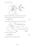
dropped into a heated split mould (Fig.
27.8).
As
the polyester used is a
thermoset
it will
Mould
.A
::
.!
C
GFRP
Slug
Mould
M
Heat and pressure
Fig. 27.8.
Compression moulding
of
car-body components.
Materials
and
energy
in
car
design
271
'go
off' in the hot mould, after which the solid moulding can be ejected. Modern
methiods
allow a press like this to produce one moulding per minute
-
still
slower
than
stee! pressing, but practical. Moulding (as this is called) brings certain advantages.
It
~ffers great design flexibility
-
particularly in change of section, and sharp detail
-
which cannot be achieved with steel. And
GF'RP
mouldings often result in
conslolidation
of
components, reducing assembly costs.
The conclusions ar'e set out in the table below.
For
Against
Retains a
I I
existing tech nology Weight saving only appreciable
in
designing against
plastic flow
Use
in
selected applications, e.g. bumpers.
For
Against
~
Large weight saving in both body shell and engine
Retains much existing tec:hnology flexibility
Corrosion resistance excellent
Unit cost higher
Deep drawing properties poor
-
loss
in design block
Aluminium alloy offers, saving
of
up to
40%
in total car weight. The increased unit cost
is
offset by the
lower running cost
of
the
lighter vehicle, and the greater recycling potential
of
the aluminium.
For
Against
Large weight saving in body shell
Corrosion resistance exc'ellent
Greai gain in design flexibility and some parts
Unit cast higher
Massive changes in manufacturing technology
Designer must cope with some creep
conisolidation
GFIRP
offers savings
of
up
to
30%
in total car weight, at some increase in unit cost and considerable
capital inveesiment in new equipment. Recycling problems still have to be overcome.
rm
1-
(a)
Commodity A
is
currently consumed at the rate
CA
tonnes per year, and
commodity
B
at the rate
CB
tonnes per year
(C,
>
CB).
If the
two
consumption
rates are increasing exponentially to give growths in consumption after each year
of
Y,%
and
rB%,
respectively
(rA
<
Y~),
derive an equation for the time, measured
from the present day, before the annual consumption of
B
exceeds that
of
A.
(13)
The table shows 1994 figures for consumptions and growth rates
of
steel,
aluminium and plastics. What are the doubling times (in years)
for
consump-
tion of thesle commodities?
(I:)
Calculate the number of years, measured from 1994, before the consumption of
(a) aluminium and
(b)
polymers would exceed that of steel,
if
exponential
growth
contintled.
Is this continued growth probable?
Material
Current
[I
994)
world
Consumption
{tomes year-')
Proiected
growth
rate
in
consumption
(%
year-',
(
T
994))
Iron
and
steel
Aluminium
Polymers
3
x
1Q8
1
x
1Q8
4~
107
2
3
A
Answers:
(b)
Doubling times: steel,
35
years; aluminium, 23 years; plastics,
18
years.
(c)
If exponential growth continued, aluminium would overtake steel in 201
years
(AD.
2195); polymers would overtake steel in
55
years (AD. 2049).
.
(a)
Discuss ways of conserving engineering materials, and the technical and
social
problems involved in implementing them.
(b)
12%
of
the world production of lead
is
used dissipatively
as
an antiknock
cornpound in petrol. If laws were passed to prevent this use, how many years
would it require before the consumption of lead returned to the level obtaining
&st
before the new laws took effect? Assume that the other uses
of
lead
continue to1 grow at an average rate
of
2%
per year.
Answer:
(b)
6.4
years.
274
Engineering Materials
1
3.
(a) Explain what is meant by
exponential
growth in the consumption of a
material.
(b) A material is consumed at
Co
tonne year-' in 1994. Consumption in 1980 is
increasing at
r%
year-'.
If
the resource base of the material is
Q
tonnes, and
consumption continues to increase at
r%
year-', show that the resource will be
half exhausted after a time,
ty,
given by
100
tx
=
-In
{A
+
1).
Y
200co
(c)
Discuss, giving specific examples, the factors that might cause a decrease in the
rate of consumption of a potentially scarce material.
4.
Use the information given in Table 2.1 (Prices of Materials) and in Table 2.4 (Energy
Content of Materials) to calculate the approximate cost of (a) aluminium, (b) low-
density polyethylene,
(c)
mild steel and (d) cement in 2004, assuming that oil
increases in price by a factor of 1.6 and that labour and other manufacturing costs
increase by a factor of 1.3 between 1994 and 2004.
Comment on the implications of your results (e.g. Which commodities have
increased by the largest factor? How have the relative costs of materials changed?
What are the implications for the use of polymers?).
Answers: (a) aluminium, Urn1448 (US$2172) tonne-'; (b) polyethylene, W932
(US$1398) tonne-';
(c)
mild steel, UK€440 (US$660) tonne-I; (d) cement, UlG78
(US$117) tonne-'.
5.
(a) Define Poisson's
ratio,
u,
and the
dilatation,
A,
in the straining of an elastic
solid.
(b) Calculate the dilatation
A
in the uniaxial elastic extension of a bar of material,
assuming strains are small, in terms of
u
and the tensile strain,
E.
Hence find the
value of
u
for which the volume change during elastic deformation is zero.
(c)
Poisson's ratio for most metals is about 0.3. For cork it is close to zero; for
rubber it is close to
0.5.
What are the approximate volume changes in each of
these materials during an elastic tensile strain of
E?
Answers: (b)
0.5,
(c)
'most metals':
0.46;
cork:
E;
rubber:
0.
6.
The potential energy
U
of two atoms, a distance
Y
apart, is
Given that the atoms form a stable molecule at a separation of 0.3nm with an
energy of
4
eV, calculate
A
and
B.
Also find the force required to break the
molecule, and the critical separation at which the molecule breaks. You should
sketch art energy/distance curve for the atom, and sketch beneath this curve the
appropriate force/distance curve.
Answers:
A:
7.2
X
10-20Jnm2;
B:
9.4
X
10-25Jnm'o; Force: 2.39
X
10-9N at
0.352 nm.
Appendix
1
Examples
27’5
7.
The potential energy
kT
of
a pair of atoms in a solid can be written as
-A
B
u=-+-
Trn
Y”
where
Y
is
the separation
of
the atoms, and
A,
B,
m
and
n
are positive constants.
Indicate the physical significance of the two terms in this equation.
A
material has a cubic unit cell with atoms placed at the corners
of
the cubes.
Show that, when the material
is
stretched in a direction parallel to one
of
the cube
edges, Young’s modulus
E
is given by
mnkTM
E=
91
where
91
is
the mean atomic volume,
k
is Boltzmann’s constant and
TM
is
the
absolute melting temperature of the solid. You may assume that
U(v,)
=
-kTM,
where
Y,
is
the equilibrium separation of a pair
of
atoms.
.
The table below gives the Young’s modulus,
E,
the atomic volume,
0,
and the
melting temperature,
T,,
for a number
of
metals. If
(where
k
is
Bolltzmann’s constant and
A
is
a constant), calculate and tabulate the
value
of
the constant
A
for each metal. Hence find an arithmetic mean of
A
for these
metals.
Use the equation, with the average
A,
to calculate the approximate Young’s
modulus of (a) diamond and (b) ice. Compare these with the experimental values
of
1.0
X
1012Nm-2 and
7.7
X
109Nm-2, respectively. Watch the units!
Material
ox
7029
fm31
Nickel
Copper
!jibe:
Aluminium
Lead
Iron
Vanadium
Chrom i
urn
I\iiobium
Moiybdenum
?antalum
Tungsten
1.09
1.18
1.71
1.66
3.03
1.18
1.40
1.20
1.80
1.53
1.80
1.59
1726
1356
1234
933
600
1753
21 73
21 63
2741
2883
3271
3683
21 4
124
76
69
Id
196
130
r
00
360
180
406
289
276
Engineering Materials
1
Data for ice and for diamond.
Ice Diamond
n
=
3.27
x
10-291113
n
=
5.68
x
10-3om3
TM
=
273K
TM
=
4200K
E
=
7.7
x
109~~-2
E
=
1.0
X
101’Nm-’
Answers:
Mean
A
=
88. Calculated moduli: diamond, 9.0
X
10” Nm-’; ice, 1.0
X
1O1O
N
m-2.
9.
(a) Calculate the density of an f.c.c. packing of spheres of unit density.
(b) If these same spheres are packed to form a
glassy
structure, the arrangement is
called ’dense random packing’ and has a density of 0.636. If crystalline f.c.c.
nickel has a density of 8.90 Mg m-3, calculate the density of glassy nickel.
Answers:
(a) 0.740, (b) 7.65 Mg m-3.
10.
(a) Sketch three-dimensional views of the unit cell of a b.c.c. crystal, showing a
(100)
plane, a
(110)
plane, a
(111)
plane and a (210) plane.
(b) The slip planes of b.c.c. iron are the
(110)
planes: sketch the atom arrangement
in these planes, and mark the
(111)
slip directions.
(c) Sketch three-dimensional views of the unit cell of an f.c.c. crystal, showing a
[100], a [1101, a
[1111
and a [2111 direction.
(d) The slip planes of f.c.c. copper are the
(1111
planes: sketch the atom
arrangement in these planes and mark the
(110)
slip directions.
11.
(a) The atomic diameter
of
an atom of nickel is 0.2492nm. Calculate the lattice
constant
a
of f.c.c. nickel.
(b) The atomic weight of nickel is 58.71 kg kmol-l. Calculate the density
of
nickel.
(Calculate first the mass per atom, and the number of atoms in a unit cell.)
(c)
The atomic diameter of an atom of iron is 0.2482nm. Calculate the lattice
constant
a
of b.c.c. iron.
(d) The atomic weight of iron is 55.85 kg kmol-I. Calculate the density of iron.
Answers:
(a) 0.352 nm, (b) 8.91 Mg m-3, (c) 0.287 nm, (d) 7.88 Mg m-3.
12.
Crystalline copper and magnesium have face-centred-cubic and close-packed-
hexagonal structures respectively.
(a) Assuming that the atoms can be represented as hard spheres, calculate the
(b)
Calculate, from first principles, the dimensions of the unit cell in copper and in
(The densities
of
copper and magnesium are 8.96 Mg m-3 and 1.74
Mg
m-3,
respectively.)
Answers:
(a) 74% for both; (b) copper:
a
=
0.361 nm; magnesium:
a
=
0.320nm;
c
=
0.523 nm.
percentage of the volume occupied by atoms in each material.
magnesium.
Appendix
’I
Examples
277
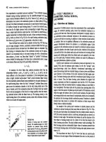
13.
The table lists ?oung’s modulus,
Ecomposite,
for a glass-filled epoxy composite. The
material consists of
a
volume fraction
Vi
of glass particles (Young’s modulus,
.Efi
$OGNm-’)
dispersed in a matrix of epoxy (Young’s modulus,
E,,
Volume
fraction
of
glass,
Vf
Ecomposife
(GN
m-’J
0
0.05
0.10
0.15
0.20
0.25
0.30
5.0
5.5
6.4
7.8
9.5
11.5
i
4.0
Calculate the upper and lower values for the modulus of the composite material,
and plot them, together with the data, as a function of
Vf
Which set of values most
nearly describes the results? Why? How does the modulus of a random chopped-
fiibre composite differ from those
of
an aligned continuous-fibre composite?
14.
Pi
composite material consists of parallel fibres of Young’s modulus
E,
in
a
matrix
elf
Young’s modulus
E,.
The volume fraction of fibres
is
V,.
Derive an expression
flor
Ec,
Young’s modulus
of
the composite along the direction of the fibres, in terms
of
EF,
EM
and
VF
Obtain an analogous expression for the density of the composite,
pc.
Using material parameters given below, find
pc
and
Ec
for the following
composites:
(a)
carbon fibre-epoxy resin
(VF
=
0.5),
(b) glass fibre-polyester resin
(V,
=
0.51,
(c)
steel-concrete
(VF
=
0.02).
A
uniform, rectangular-section beam of fixed width
w,
unspecified depth
d,
and
fixed length
L
rests horizontally on two simple supports at either end of the beam.
A.
concentrated force
F
acts vertically downwards through the centre
of
the beam.
The deflection,
6,
of
the loaded point is
FL3
6
=
4Ecwd3
ignoring the deflection due to self weight. Which of the three composites will give
the lightest beam for
a
given force and deflection?
Material
Densiv
Young‘s
modulus
hfg
m-31
(GNm-2j
Carbon fibre
1.90
Glass
fibre
2.55
Epoxy
resin
Polyester resin
Steel
7.90
Concrete
2.40
]
1.15
390
72
3
200
45
278
Engineering Materials
1
Answers:
Ec
=
EFVF
+
(1
-
VF)EM;
pc
=
~FVF
+
(1
-
VF)
p~.
(a)
pc
=
1.53Mgm-3,
Ec
=
197GNm-2; (b)
pc
=
1.85Mgm-3,
Ec
=
37.5GNm-2;
(c)pc
=
2.51
Mg
m-g
Ec
=
48.1 GN m-'.
Carbon fibre/Epoxy resin.
15.
Indicate, giving specific examples, why some composite materials are particularly
attractive in materials applications.
A
composite material consists of flat, thin metal plates of uniform thickness
glued one to another with a thin, epoxy-resin layer (also of uniform thickness) to
form a 'multi-decker-sandwich' structure. Young's modulus of the metal is
E,,
that
of the epoxy resin is
E2
(where
E2
<
El
)
and the volume fraction of metal is
V,
.
Find
the ratio of the maximum composite modulus to the minimum composite modulus
in terms of
E,,
E2
and
V,
.
Which value
of
V,
gives the largest ratio?
Answer:
Largest ratio when
V1
=
0.5.
16.
(a) Define a high polymer; list three engineering polymers.
(b) Define a thermoplastic and a thermoset.
(c)
Distinguish between a glassy polymer, a crystalline polymer and a rubber.
(d) Distinguish between a cross-linked and a non-cross-linked polymer.
(e) What is a co-polymer?
(f)
List the monomers
of
polyethylene
(PE),
polyvinyl chloride (PVC), and
(g) What is the glass transition temperature,
TG?
(h) Explain the change of moduli of polymers
at
the glass transition
temperature.
(i) What is the order of magnitude of the number of carbon atoms in a single
molecule of a high polymer?
(j)
What is the range of temperature in which
TG
lies for most engineering
polymers?
(k) How would you increase the modulus of a polymer?
polystyrene
(PS).
17.
(a) Select the material for the frame of the ultimate bicycle
-
meaning the lightest
possible for a given stiffness. You may assume that the tubes of which the frame
is made are cantilever beams (of length
1)
and that the elastic bending
displacement
6
of
one
end
of
a
tubular beam under a force
F
(the other end
being rigidly clamped) is
~13
6
=
3Erir3t
2r
is the diameter
of
the tube (fixed by the designer) and
t
is the wall thickness
of the tube, which you may vary.
t
is much less than
r.
Find the combination of
material properties which determine the mass of the tube for a given stiffness,
and hence make your material selection using data given in Chapters 3 and
5.
Try steel, aluminium alloy, wood, GFRP and
CFRP.
Appendix
1
Examples
279
(b) Which of the following materials leads to the cheapest bicycle frame, for
a
given
stiffness: mild steel, aluminium alloy, titanium alloy,
GFRP,
CFRP
or
wood?
Ai~swers:
(a)
CEW,
(b) steel.
18.
Explain what
is
meant by the
ideal
strength
of
a
material. Show how dislocations can
allow metals and alloys to deform plastically at stresses that are much less than the
ideal strength. Indicate, giving specific examples, the ways in which metals
and
alloys may be made harder.
19.
The energy per unit length of a dislocation is
xGb2.
Dislocations dilate a close-
packed crystal structure very slightly, because at their cores, the atoms are not
close-packed: thle dilatation
is
xb2
per unit length of dislocation. It
is
found that the
density of
a
bar of copper changes from 8.9323
Mg
mP3 to 8.9321
Mg
mW3 when it
is
very
heavily deformed. Calculate (a) the dislocation density introduced into the
ccspper by the deformation and (b) the energy associated with that density.
Compare this result with the latent heat of melting of copper (1833MJm-3)
(b
for
copper
is
0.256nm;
G
is
%E).
Answers:
(a)
1.4
X
1015m-2, (b) 2.1 MJm-3
20.
Explain briefly what is meant by a
dislocation.
Show with diagrams how the motion
of
(a)
an edge dislocation and
(b)
a screw dislocation can lead to the plastic
deformation of a crystal under an applied shear stress. Show how dislocations can
account for the following observations:
(a)
cold working makes aluminium harder;
(b)
an alloy of
20%
Zn,
80%
Cu
is
harder than pure copper;
(c)
the hardness of nickel is increased by adding particles
of
thorium oxide.
2%.
(a)
Derive an expression for the shear stress
T
needed to bow a dislocation line into
a
semicircle between small hard particles a distance
L
apart.
(b)
A
polycrystalline aluminium alloy contains a dispersion
of
hard particles of
diameter
lop8
m
and average centre-to-centre spacing of 6
X
lo4
rn
measured in
the
slip
planes. Estimate their contribution to the tensile yield strength,
uyr
of
the alloy.
(c)
The
alloy is used for the compressor blades of
a
small turbine. Adiabatic
heating raises the blade temperature to 150°C, and causes the particles to
coarsen
slowly.
After 1000 hours they have grown to
a
diameter of 3
X
IQ-sm
and are spaced
18
X
apart. Estimate the drop in yield strength. (The
shear modulus of aluminium is 26GNmP2, and
b
=
0.286nm.)
Anszuers:
(b)
450
MN mF2,
(c)
300 MN m-'.
280
Engineering Materials
1
22.
Nine strips of pure, fully annealed copper were deformed plastically by being
passed between a pair of rotating rollers
so
that the strips were made thinner and
longer. The increases in length produced were
1,
10,20,30,40,50,60,70 and 100%
respectively. The diamond-pyramid hardness of each piece was measured after
rolling. The results were
Nominal strain 0.01
0.1
0.2
0.3
0.4
0.5
0.6 0.7 1.0
Hardness/MNm”
423
606 756
870
957
1029 1080 1116 1170
Assuming that a diamond-pyramid hardness test creates a further nominal strain, on
average, of
0.08,
and that the hardness value is 3.0 times the true stress with this extra
strain, construct the curve of nominal stress against nominal strain, and find:
(a) the tensile strength of copper;
(b)
the strain at which tensile failure commences;
(c)
the percentage reduction in cross-sectional area at this strain;
(d) the work required to initiate tensile failure in a cubic metre of annealed
copper.
Why can copper survive a much higher extension during rolling than during a
tensile test?
Answers: (a) 217MNm-’, (b) 0.6 approximately,
(c)
38%, (d)
109MJ.
23.
(a)
If
the true stress-true strain curve for a material is defined by
u
=
A&“,
where
A
and
n
are constants,
find the tensile strength
uTS.
(Method: first find the equation of the nominal
stress-nominal strain curve, assuming flow does not localise. Differentiate to
find the maximum of this curve. Hence find the strain corresponding to the
tensile strength. Use this to find the tensile strength itself.)
(b) For a nickel alloy,
n
=
0.2, and
A
=
800
MN m-2. Evaluate the tensile strength of
the alloy. Evaluate the true stress in an alloy specimen loaded to
uTS.
AHn
en
Answevs: (a)
uTS
=
-
,
(b)
uTS
=
475 MN m-2,
u
=
580 MN m-’.
24.
(a) Discuss the assumption that, when a piece of metal is deformed at constant
temperature, its volume is unchanged.
(b)
A
ductile metal wire of uniform cross-section is loaded in tension until it just
begins to neck. Assuming that volume is conserved, derive a differential
expression relating the true stress to the true strain at the onset of necking.
(c)
The curve of true stress against true strain for the metal wire approximates to
u
=
350~O.~MNm-~.
Appendix
1
Examples
287
Estimate the tensile strength of the wire and the work required to take
1
m3
of
the wire to the point of necking.
Answers:
(c)
163
MN
m-’, 69.3
MJ.
2%.
(a)
One type of hardness test involves pressing a hard sphere (radius
r)
into the test
material under a fixed load
F,
and measuring the
depth,
h,
to which the sphere
sinks into the material, plastically deforming it. Derive an expression
for
the
indentation hardness,
H,
of the material in terms of
h,
F
and
Y.
Assume
h
<<
(b)
The indentation hardness,
H,
is found to be given
by
N
=
30,
where
uY
is the
true yield stress at a nominal plastic strain of
8%.
If (as in question
23)
the true
stress-strain curve of a material
is
given by
r.
and
n
=
0.2,
calculate the tensile strength of a material
for
which the indentation
hardness
is
600MNm-’. You may assume that
uTS
=
Ann/en
(see question
23).
Answers:
(a>
H
:=
~
,
(b)
CTTS
=
198MNm-’.
F
2~rh
26.
A
metal bar of width
w
is
compressed between two hard anvils as shown in Fig.
A1.1.
The third dimension of the bar,
L,
is
much greater than
w.
Plastic deformation
takes glace as a result of shearing along planes, defined by the dashed lines
in
the
figure, at
a
shear stress
k.
Find an upper bound
for
the load
F
when (a) there
is
no
friction between anvils and bar, and (b) there
is
sufficient friction to effectively weld
the anvils to the bar. Show that the solution to case (b) satisfies the general
formula
which defines upper bounds for all integral values of
w/2d.
LWI
Fig.
Al.l.
282
Engineering Materials
1
A composite material used for rock-drilling bits consists of an assemblage of
tungsten carbide cubes (each
2
p,m in size) stuck together with a thin layer of cobalt.
The material is required to withstand compressive stresses of
4000
MN m-’ in
service. Use the above equation to estimate an upper limit for the thickness of the
cobalt layer.
You
may assume that the compressive yield stress of tungsten carbide
is well above 4000MNrn-’, and that the cobalt yields in shear at
k
=
175MNm-’.
What assumptions made in the analysis are likely to make your estimate
inaccurate?
Answers:
(a)
2wLk,
(b)
3wLk;
0.048
pm.
27.
By calculating the plastic work done in each process, determine whether the bolt
passing through the plate in Fig.
A1.2
will fail, when loaded in tension, by yielding
of the shaft or shearing-off of the head. (Assume no work-hardening.)
Answer:
The bolt will fail by shearing-off of the head.
I
I
I
p
32
-
I
I
Dimensions
in
rnrn
I
Fig.
Al.2.
u
28.
Sketch curves of the nominal stress against nominal strain obtained from tensile
tests on (a) a typical ductile material,
(b)
a typical non-ductile material. The
following data were obtained in a tensile test on a specimen with 50mm gauge
length and a cross-sectional area of 160mm’.
Extension/mm
0.050 0.100 0.150 0.200 0.250 0.300 1.25 2.50 3.75 5.00 6.25 7.50
Load/kN
12 25 32 36
40
42
63 80 93 100 101 90
Appendix
1
Examples
283
The total elongation of the specimen just before final fracture was 1670, and the
reduction in area at the fracture was 64%.
Find the maximum allowable working stress if this is to equal
(a)
0.25
X
Tensile strength,
(bb
0.6
X
0.1% proof stress.
(c)
What would have been the elongation and maximum reduction
in
area
if
a
I50 mm gauge length had been used?
Answers:
(a) 160MNm-’; (b) 131 MNm-’;
(c)
12.85%,
64%.
29.
A
large thick plate of steel is examined by X-ray methods, and found to contain no
detectable cracks. The equipment can detect a single edge-crack
of
depth
a
=
1
mm
or greater. The steel has a fracture toughness
Kc
of 53 MN
rn-%
and a yield strength
of
950MNm-’. Assuming that the plate contains cracks on the limit of detection,
determine whether the plate will undergo general yield or will fail by fast fracture
before general yielding occurs. What is the stress at which fast fracture wou%d
occur?
Answer:
Failure by fast fracture at 946MNm-’.
30.
Two
wooden beams are butt-jointed using an epoxy adhesive (Fig.
A1.3).
The
adhesive was stirred before application, entraining air bubbles which, under
pressure in forming the joint, deform to flat, penny-shaped discs
of
diameter
2a
=
2mm.
If the beam has the dimensions shown, and epoxy has
a
fracture toughness
of
0.5
MN m-%, calculate the maximum load
F
that the beam can support. Assume
K
=
o,i%
for the disc-shaped bubbles.
Answer:
2.97
W.
f
72
t=b=O.lm;/=2m
Fig.
AI
.3.
284
Engineering Materials
1
31.
A component is made of a steel for which
K,
=
54
MN m-%. Non-destructive testing
by ultrasonic methods shows that the component contains cracks of up to 2a
=
0.2mm in length. Laboratory tests show that the crack-growth rate under cyclic
loading is given by
da
dN
-
=
A(Am4,
where
A
=
4
X
stress of range
(MN rn-’)+ m-l. The component is subjected to an alternating
Ao
=
180
MN m-*
about a mean tensile stress of
A0/2.
Given that
AK
=
AD&%,
calculate the number
of cycles to failure.
Answer: 2.4
X
lo6
cycles.
32.
When a fast-breeder reactor is shut down quickly, the temperature of the surface of
a number of components drops from
600°C
to
400°C
in less than a second. These
components are made of a stainless steel, and have a thick section, the bulk of
which remains at the higher temperature for several seconds. The low-cycle fatigue
life of the steel is described by
N;’*
A&
=
0.2
where
Nf
is the number of cycles to failure and
A@’
is the plastic strain range.
Estimate the number of fast shut-downs the reactor can sustain before serious
cracking or failure will occur. (The thermal expansion coefficient of stainless steel
is
1.2
X
10-5K-1;
the appropriate yield strain at
400°C
is
0.4X10⁻³.)
Answer:
lo4
shut-downs.
33.
(a) An aluminium alloy for an airframe component was tested in the laboratory
under an applied stress which varied sinusoidally with time about a mean
stress of zero. The alloy failed under a stress range,
Ao,
of
280
MN m-2 after
lo5
cycles; under a range of
200
MN m-2, the alloy failed after
lo7
cycles. Assuming
that the fatigue behaviour of the alloy can be represented by
where
a
and
C
are material constants, find the number of cycles to failure,
Nj,
for a component subjected to a stress range of
150MNm-’.
(b) An aircraft using the airframe components has encountered an estimated
4x10’
cycles at a stress range of l50MNm-’. It is desired to extend the airframe life
by another
4
X
10’
cycles by reducing the performance of the aircraft. Find the
Appendix
1
Examples
285
decrease in stress range necessary to achieve this additional life.
You
may
assume a simple cumulative-damage law of the form
for this calculation.
Indicate briefly how the following would affect the fatigue life
of
the
components:
(a)
a
good surface finish;
(b)
the presence of a rivet hole;
(c)
a
significant mean tensile stress;
(d)
a
corrosive atmosphere.
Answers:
(a) 5.2X10' cycles, (b) 13MNm-2
. A
cylindrical steel pressure vessel of
7.5
m diameter and
40
mm wall thickness
is
to
operate at a working pressure of 5.1 MNm-'. The design assumes that failure
will
take place by fast fracture from a crack which has extended gradually along the
length of the vessel by fatigue. To prevent fast fracture, the total number
of
loading
cycles from zero to full load and back to zero again must not exceed 3000.
The fracture toughness for the steel
is
200 MN m-%. The growth of the crack by
fatigue may be represented approximately by the equation
where
A
=
2.44X10⁻¹⁴
(MN
m-2)4 m-I, da/dN is the extent of crack growth per load
cycle and
K
is
the stress intensity factor for the crack.
Find the minimum pressure to which the vessel must be tested before use to
guarantee against failure
in
under the 3000 load cycles.
Answer:
8.97MNm-'.
35.
Use
your
knowledge of diffusion to account for the following observations:
(a)
Carbon diffuses fairly rapidly through iron at 100"C, whereas chromium does
(b)
Diffusion
is
more rapid in polycrystalline silver with a small grain size than in
mot.
coarse-grained silver.
Give an approximate expression for the time
t
required for significant diffusion
to
take place
over
a distance
x
in
terms of
x,
and the diffusion coefficient,
D.
A
component
is
made from an alloy
of
copper with
18%
by
weight
of
zinc. The
286
Engineering Materials
1
concentration of zinc is found to vary significantly over distances of 10 km.
Estimate the time required for a substantial levelling out of the zinc concentration
at 750°C. The diffusion coefficient for zinc in the alloy is given by
D
=
D~~-Q/RT
where
constants
Do
and
Q
have the values
9.5
mm2
s-'
and 159 kJ mol-', respectively.
is the universal gas constant and
T
is the absolute temperature. The
Answers:
t
=
x2/D;
23 min.
36.
It is found that a force
F
will inject a given weight of a thermosetting polymer into
an intricate mould in 30
s
at 177°C and in 81.5
s
at 157°C. If the viscosity of the
polymer follows an
Avrhenius Law,
with a rate of process proportional to e-Q'RT,
calculate how long the process will take at 227°C.
Answer:
3.5
s.
37.
Explain what is meant by
creep
in materials. What are the characteristics of a creep-
resistant material?
A cylindrical tube in a chemical plant is subjected to an excess internal pressure
of
6
MN
m-2, which leads to a circumferential stress in the tube wall. The tube wall
is required to withstand this stress at a temperature of 510°C for 9 years. A designer
has specified tubes of
40
mm bore and 2 mm wall thickness made from a stainless
alloy of iron with 15% by weight of chromium. The manufacturer's specification for
this alloy gives the following information:
Temperature
("C)
618 640 660 683
707
Steady-state creep rate
k
(s-l),
for an applied tensile stress
u
of
200
MN
m-*
1.0
x
1.7
x
4.3
x
7.7
x
2.0
x
10"
Over the present ranges of stress and temperature the alloy can be considered to
creep according to the equation
where
A
and
Q
are constants,
R
is the universal gas constant, and
T
is the absolute
temperature. Given that failure is imminent at a creep strain of
0.01
for the present
alloy, comment on the safety of the design.
Answer:
Strain over
9
years
=
0.00057; design safe.
38.
Explain what is meant by
diffusion
in materials. Account for the variation of diffusion
rates with (a) temperature, (b) concentration gradient and
(c)
grain size.
An alloy tie bar in a chemical plant has been designed to withstand a stress,
G,
of 25MNrn-' at 620°C. Creep tests carried out on specimens of the alloy under
Appendix
1
Examples
287
these conditions indicated a steady-state creep-rate,
E,
of 3.1
X
~O-”S-~.
In service
it was found that, for 30% of the running time, the stress and temperature increased
to 30
MN
rn-’ and 650°C. Calculate the average creep-rate under service conditions.
It may be assumed that the alloy creeps according to the equation
(c_
=
Ao5e-Q/ET
where
A
and
Q
are constants,
i?
is the universal gas constant and
T
is
the absolute
temperature.
Q
has a value of 160kJmol-’.
Answer:
6.82
X
10-12s-1.
39.
The oxidation of a particular metal in air is limited by the outward diffusion of
metallic ions through an unbroken surface film of one species of oxide. Assume that
the concentration of metallic ions in the film immediately next to the metal
is
cl,
and that the concentration of ions in the film immediately next to the air
is
c2,
where
c1
and
c2
are constants. Use Fick‘s First Law to show that the oxidation of the
metal should satisfy parabolic kinetics, with weight gain
Am
given by
(Am)’
=
kpt.
The oxidation of another metal is limited by the outward flow of electrons through
a un:iform, unbroken oxide film. Assume that the electrical potential in the
film
immediately next to the metal
is
VI,
and the potential immediately next to the free
surface
is
V,,
where
V1
and
V,
are constants. Use Ohm’s Law
to
show that
parabolic kinetics should apply in this case also.
40.
The kinetics
of
oxidation of mild steel at high temperature are parabolic, with
138 kJ mol-’
k,
(kg2
m-4s-1)
=
37 exp
Find the depth of metal lost from the surface of a mild steel tie bar in a furnace at
500°C
after
1
year. You may assume that the oxide scale
is
predominantly FeO. The
atomic weight and density of iron are
55.9
kg
kmol-I and 7.87Mgm”; the atomic
weight of oxygen is 16 kg kmol-l. What would be the
loss
at 600°C?
Answers:
0.33mm
at
500°C;
1.13mm at
600°C.
41.
Explain the following observations, using diagrams to illustrate your answer
wherever you can.
(a)
A
reaction vessel for a chemical plant was fabricated by welding together
stainless-steel plates (containing
18%
chromium,
8%
nickel and
0.1%
carbon by
weight). During service the vessel corroded badly at the grain boundaries near
the welds.
288
Engineering Materials
1
(b) Mild-steel radiators in a central-heating system were found to have undergone
little corrosion after several years' service.
(c)
In order to prevent the corrosion of a mild-steel structure immersed in sea
water, a newly qualified engineer suggested the attachment of titanium plates
in the expectation of powerful cathodic action. He later found to his chagrin
that the structure had corroded badly.
42.
Explain the following observations, using diagrams to illustrate your answer
wherever possible:
Diffusion of aluminium into the surface of a nickel super-alloy turbine blade
reduced the rate of high-temperature oxidation.
Steel nails used to hold copper roofing sheet in position failed rapidly by wet
corrosion.
The corrosion of an underground steel pipeline was greatly reduced when the
pipeline was connected to a buried bar of magnesium alloy.
Measurements of the rate
of
crack growth in brass exposed to ammonium
sulphate solution and subjected to a constant tensile stress gave the following
data:
Nominal
stress
u
[MN
m-2
1
Crack
growth rate
da/dt
(mm
year-')
4
A
8
0.25
0.50
0.25
0.3
0.6
1.2
Show that these data are consistent with a relationship of form
where
K
=
(T<~FU
is the stress intensity factor. Find the values of the integer
n
and
the constant
A.
(b) The critical strain energy release rate,
G,,
for brass in the present environment
is
55
kJ mP2, with
a
Young's modulus
of 110
GN
m-'. It is proposed to use the
brass for piping in an ammonium sulphate plant. The pipes must sustain a
circumferential tensile stress of
85
MN
mW2, and experience has shown that
longitudinal scratches
0.02
mm deep are likely to occur on the inner surfaces of
the pipes. Estimate the time that a pipe would last without fracturing once the
solution started to
flow
through it.
(c) How might you protect the inside of the pipe against chemical attack?
Anszuers:
(a)
n
=
2,
A
=
0.0239
m4
MN-2
yearp1; (b)
6.4
days.
Appendix
1
Examples
289
44,
Under aggressive corrosion conditions it is estimated that the maximum corrosion
current density in a galvanised steel sheet will be
6
X
IO”
A
m-2.
Estimate the
thickness of the galvanised layer needed to give a rust-free life of at least
5
years.
The density of zinc
is
7.13Mgm-3, and its atomic weight is 45.4. Assume that the
zinc corrodes to give Zn2+ ions.
Answer:
0.045 mm.
45.
A sheet of steel of thickness 0.50mm is tinplated on both sides and subjected to
a
corrosive environment. During service, the tinplate becomes scratched,
so
that steel
is
exposed over 0.5% of the area of the sheet. Under these conditions it
is
estimated
that the current consumed at the tinned surface by the oxygen-reduction reaction
is
2
X
18”
A
m-’. Will the sheet rust through within
5
years in the scratched
condition? The density of steel
is
7.87Mgm-3. Assume that the steel corrodes to
give Fez+ ions. The atomic weight of iron is
55.9.
Answer:
Yes.
46.
(a) Explain the origins of friction between solid surfaces in contact.
(b)
Soft rubbers do not obey the law of friction
F,
=
ysP
(where
F,
is
the sliding
force,
P
the normal force acting across the surfaces and
ps
the coefficient
of
static friction). Instead,
F,
increases with the nominal contact area
A
(for this
reason racing cars have wide tyres). Explain this.
(c)
Wow
does lubrication reduce friction? How can friction between road and tyre
be maintained even under conditions of appreciable lubrication?
47,
It
is
observed that snow lies stably on roofs with a slope of less than
24”,
but that
it slides off roofs with a greater slope. Skiers, on the other hand, slide
on
a
snow-
covered mountain side with a slope
of
only
2”.
Why
is
this?
A
man
of
weight
100
kg standing on skis 2m long and
0.18
m wide slides on the
2”
mountain slope, at
0°C.
Calculate the work done against friction when the
ski
slides
a distance equal
to
its own length. Hence calculate the average thickness
of
the water film beneath each ski. (The latent heat of fusion of ice
is
330MJmP3.)
Answers:
Work done 69J; average film thickness
=
0.5
pm.
Appendix
2
Aids
and demonstrations
The following is a summary of visual aids (slides, artefacts and demonstrations) that
may be found helpful in presenting the material in this book. Material for slides may
be found in this book; in the further reading at the ends of the chapters; and in other
readily available sources (indicated by references
[ll
to
151
and listed at the end of
Appendix 2). Where material for slides needs to be found from more specialised
publications and reports we have given appropriate references. Copyright permission
should, of course, be obtained where applicable.
Chapter
3
Slides:
S.
S.
Sckenectady
after fast fracture in dock
Ill;
sectioned drawing of turbofan
aero-engine
[21;
sectioned drawing of spark plug; sailing cruisers (from yachting
magazines); bridges.
Artefacts:
Screwdrivers; dismantled spark plug; PVC yachting anorak, polymer rope,
etc.
Chapter
2
Slides:
Map of World (to illustrate strategic factors); open-cast copper mine (to
emphasise energy needed to extract ores); recycling of scrap metals, glass, building
materials, etc.
Chapter
3
Slides:
Vaulting pole, springs, girders (for extremes of stiffness).
Demonstrations:
(a)
Foam polyurethane
=40
X
5
X
5cm pulled along its length
in
tension.
(b)
Foam
=
60
X
60
X
10
cm glued into square wooden frame hinged at all four
corners and sheared.
(c)
Foam 20-cm cube loaded in compression by 10-kg weight on
wooden platten to give
=
4%
strain;
E
=
lo4
GN m-'. (d) Rods of steel, glass, wood
=
6 mm diameter
X
0.75 m long suspended by string at each end (Fig.
3.4)
with 0.5-kg
weight at mid point;
f
values
=
10,
6 and 2
s-'.
Chapter
4
Demonstrations:
(a)
Atom spring models (Fig. 4.2) on overhead projector to illustrate
effect of structure on modulus. (b) Large models of Na atom and C1 atom.
(c)
Liquid
nitrogen.
Appendix
2
Aids and demonstrations
291
Chapter
5
Demonstrations:
(a) Give four injection-moulded close-packed planes to each student to
allow personal building of
f.c.c.
and c.p.h. (b) Atomix atomic model on overhead
projector to show atom packing (Emotion Productions Inc., 4825 Sainte Catherine
8,
Montreal
215PQ,
Canada); or ball bearings on overhead projector.
Chapter
6
Slides:
Microstructures of
GFRP,
glass-filled polymer, cermet, wood; sectioned piece
of
cord-reinforced automobile tyre.
Demon~tration~:
(a) Put 15-mm rubber tube into vacuum flask of liquid nitrogen
-
tube
should have steel rod inside to keep it straight. Take-tube out after
3
min and remove
steel rod (wearing gloves). Support tube horizontally with lagged support at each end.
Load centre
of
span with 0.5-kg weight and lagged hook. Rubber will become floppy
after
I-;!
rnin.
(b)
Glue alternate sheets of foam polyurethane and plywood together
to
make a sandwich composite
-
stiff one way, very floppy the other.
Chapter
9
Slides:
Of
reflecting telescopes, aeroplanes, space capsules, bicycles (to illustrate
applications of stiff but light materials).
Chapter
Slides:
Slab and sheet metal rolling; extrusion, etc., of polymers; tensile-testing
machines; hardness-testing machines; hardness indentations.
Demonstrations:
(a) Pull rubber band on overhead projector to show large elastic strain.
(b)
Take a piece
of
plasticine modelling material (Harbutt Ltd., Bathampton, Bath BA2
6TA,
England; from most toy shops) and roll into a rod
=
2.5 cm diameter
X
12
ern long.
Form central portion to give slightly reduced gauge section. Pull on overhead projector
to show elastic and plastic deformation and necking.
Chapter
Demonstrations:
(a) Take offcut of carpet
=
0.5
X
3
m;
put on bench and pass rucks along
(Fig.
9.6).
(b) Raft of pencils on overhead projector to simulate plank analogy (Fig.
9.10).
Slides:
Microstructures showing precipitates; electron micrographs
of
dislocation
tangles; micrographs of polycrystalline metals.
Demonstrations:
(a) Atomix (to show grain boundaries). (b) Model of dispersion
strengthening. Take piece of PMMA sheet
=
2.5
mm thick and
=
7 crn square. Glue four
PMMA
strips
of
section
=
7
X
7mm on top of the sheet to form
a
tray
=
7mm deep.
Cut
six
=
7-mm lengths
of
an 6-mm-diameter PMMA rod. Glue the ends of these
to