Biomimetics Learning from nature part 15 ppt
Bạn đang xem bản rút gọn của tài liệu. Xem và tải ngay bản đầy đủ của tài liệu tại đây (13.6 MB, 30 trang )
BiomimeticPorousTitaniumScaffoldsforOrthopedicandDentalApplications 443
Freese, H.L. ; Volas, M.G. & Wood, J.R. (2001). Metallurgy and technological properties of
titanium and its alloys, In: Titanium in Medicine, Brunette, D.M., Tengvall, P.,
Textor, M. and Thomsen, P., (Ed.), 23-51, Springer
Froes, F.H. ; Eylon, D. ; Eichelman, G.E. & Burte, H.M. (1980). Developments in Titanium
Powder Metallurgy. Journal of Metals, Vol. 32, 47-54
Fujita, T. ; Ogawa, A. ; Ouchi, C. & Tajima, H. (1996). Microstructure and properties of
titanium alloy produced in the newly developed blended elemental powder
metallurgy process. Materials Science and Engineering A, Vol. 213, 148-153
Gasser, B. (2001). Design and engineering criteria for titanium devices, In: Titanium in
Medicine, Brunette, D.M., Tengvall, P., Textor, M. and Thomsen, P., (Ed.), 673-701,
Springer
Gibson, L.J. & Ashby, M.F. (1997). Cellular Solids: Structure and Properties, Cambridge
University Press, UK
Gil, F.J. ; Padrós, A. ; Manero, J.M. ; Aparicio, C. ; Nilsson, M. & Planell, J.A. (2002). Growth
of bioactive surfaces on titanium and its alloys for orthopaedic and dental implants.
Materials Science and Engineering C, Vol. 22, 53–60
Goodman, S. ; Toksvig-Larsen, S. & Aspenberg, P. (1993). Ingrowth of bone into pores in
titanium chambers implanted in rabbits: Effect of pore cross-sectional shape in the
presence of dynamic shear. Journal of Biomedical Materials Research, Vol. 27, 247-253
Griss, P. & Heimke, G. (1976). Record of discussion on stability of joint prostheses, In:
Biocompatibility of implant materials, Williams, D., (Ed.), 52-68, Sector publishing,
London
Gutierres, M. ; Lopes, M.A. ; Sooraj Hussain, N. ; Lemos, A.F. ; Ferreira, J.M.F. ; Afonso, A.,
et al. (2008). Bone ingrowth in macroporous bonelike for orthopaedic applications.
Acta Biomaterialia, Vol. 4, 370–377
Habibovic, P. ; Barrére, F. ; van Blitterswijk, C.A. ; de Groot, K. & Layrolle, P. (2002).
Biomimetic hydroxyapatite coating on metal implants. Journal of the American
Ceramic Society, Vol. 85, 517–22
Hallab, N.J. ; Jacobs, J.J. & Katz, J.L. (2004). Application of Materials in Medicine, Biology,
and Artificial Organs: Orthopedic Applications, In: Biomaterials Science: An
Introduction to Materials in Medicine, Ratner, B.D., Hoffman, A.S., Schoen, F. and
Lemons, J.E., (Ed.), 526-555, Elsevier Academic Press
Hench, L.L. (1991). Surface reaction kinetics and adsorption of biological moieties: A
mechanistic approach to tissue attachment, In: The Bone-Biomaterial Interface, Davies,
J.E., (Ed.), 33–48, University of Toronto, Toronto
Hignett, B. ; Andrew, T.C. ; Downing, W. ; Duwell, E.J. ; Belanger, J. & Tulinski, E.H. (1987).
Surface cleaning, finishing and coating, In: Metals Handbook, vol. 5, Wood, W.G.,
(Ed.), 107–127, American Society for Metals, Metals Park, OH
Hirschhorn, J.S. ; Mcbeath, A.A. & Dustoor, M.R. (1971). Porous Titanium Surgical Implant
Materials. Journal of Biomedical Materials Research Symposium, Vol. 1, 49-67
Hirschhorn, J.S. & Reynolds, J.T. (1969). Powder metallurgy fabrication of cobalt alloy
surgical implant materials, In: Research in dental and medical materials, Korostoff, E.,
(Ed.), 137-150, Plenum Press, NY
Hoffman, A.S. (2004). Classes of Materials used in medicine: Introduction, In: Biomaterials
Science: An Introduction to Materials in Medicine, Ratner, B.D., Hoffman, A.S., Schoen,
F. and Lemons, J.E., (Ed.), 67, Elsevier Academic Press
Epidemiology and End
Results (SEER) Program. from SEER Training Modulus, National Cancer Institute.
Hungerford, D.S. & Kenna, R.V. (1983). Preliminary experience with a total knee prosthesis
with porous coating used without cement. Clinical Orthopaedic and Related Research,
Vol. 176, 95-107
Imwinkelried, T. (2007). Mechanical properties of open-pore titanium foam. Journal of
Biomedical Materials Research, Vol. 81A, 964–970,
Ishizaki, K. ; Komarneni, S. & Nanko, M. (1998). Porous Materials: Process technology and
applications, Kluwer Academic Publishers
Jasty, M. ; Kienapfel, H. & Griss, P. (2007). Fixation by Ingrowth, In: The adult hip, Callaghan,
J.J., Rosenberg, A.G. and Rubash, H.E., (Ed.), 1, 195-206, Lippincott Williams and
Wilkins, Philadelphia
Jiang, B. ; Zhao, N.Q. ; Shi, C.S. & Li, J.J. (2005). Processing of open cell aluminum foams
with tailored porous morphology. Scripta Materialia, Vol. 53, 781–785
Justino, J.G. ; Alves, M.K. ; Klein, A.N. & Al-Qureshi, H.A. (2006). A comparative analysis of
elasto-plastic constitutive models for porous sintered materials. Journal of Materials
Processing Technology, Vol. 179, 44–49
Kawalec, J.S. ; Brown, S.A. ; Payer, J.H. & Merritt, K. (1995). Mixed-metal fretting corrosion
of Ti6Al4V and wrought cobalt alloy. Journal of Biomedical Materials Research, Vol.
29, 867-873
Keaveny, T.M. (1998). Cancellous bone, In: Handbook of Biomaterial Properties, Black, J. and
Hastings, G., (Ed.), 15-23, Chapman and Hall, London
Kim, H.M. ; Miyaji, F. ; Kokubo, T. & Nakamura, T. (1996). Preparation of bioactive Ti and
its alloy via simple chemical surface treatment. Journal of Biomedical Materials
Research, Vol. 32, 409-417
Kim, H.M. ; Miyaji, F. ; Kokubo, T. & Nakamura, T. (1997a). Effect of heat treatment on
apatite-forming ability of Ti metal induced by alkali treatment. Journal of Materials
Science: Materials in Medicine, Vol. 8, 341-347
Kim, H.M. ; Miyaji, F. ; Kokubo, T. & Nakamura, T. (1997b). Bonding strength. of bonelike
apatite layer to Ti metal substrate. Journal of Biomedical Materials Research:Applied
Biomaterials, Vol. 38, 121–127
Kim, H.M. ; Miyaji, F. ; Kokubo, T. ; Nishiguchi, S. & Nakamura, T. (1999). Graded surface
structure of bioactive titanium prepared by chemical treatment. Journal of Biomedical
Materials Research Part A, Vol. 45, 100 - 107
Kokubo, T. ; Kim, H.M. & Kawashita, M. (2003). Novel bioactive materials with different
mechanical properties. Biomaterials, Vol. 24, 2161–2175
Kokubo, T. ; Miyaji, F. & Kim, H.M. (1996). Spontaneous formation of bonelike apatite layer
on chemically treated titanium metals. Journal of American Ceramic Society, Vol. 4,
1127–1129
Kokubo, T. & Takadama, H. (2006). How useful is SBF in predicting in vivo bone bioactivity.
Biomaterials, Vol. 27, 2907-2915
Kotan, G. & Bor, A.S. (2007). Production and characterization of high porosity Ti-6Al-4V
foam by space holder technique in powder metallurgy. Turkish Journal of
Engineering and Environmental Sciences
, Vol. 31, 149-156
Biomimetics,LearningfromNature444
Kramer, K.H. (2000). Implants for surgery-A survey on metallic materials, In: Materials for
Medical Engineering, Proceedings of Euromat 99, Stallforth, H. and Revell, P., (Ed.), 2,
9-29, Wiley-VCH, Weinheim
Krishna, B.V. ; Xue, W. ; Bose, S. & Bandyopadhyay, A. (2008). Engineered Porous Metals for
Implants. JOM, Vol. 60, 45-48
Kriszt, B. ; Martin, U. & Mosler, U. (2002). Characterization of cellular and foamed metals,
In: Handbook of cellular metals, Degischer, H.P. and Kriszt, B., (Ed.), 127-145, Wiley-
VCH Verlag, Weinheim
Kuhne, J.H. ; Bartl, R. ; Frisch, B. ; Hammer, C. ; Jansson, V. & Zimmer, M. (1994). Bone
formation in coralline hydroxyapatite. Effects of pore size studied in rabbits. Acta
Orthopaedica Scandinavica, Vol. 65, 246–252
Kutty, M.G. ; Bhaduri, S. ; Jokisaari, J.R. & Bhaduri, S.B. (2001). Development of gradient
porosities in Ti dental implant. Ceramic Engineering and Science Proceedings, Vol. 22,
587-592
Laptev, A. ; Bram, M. ; Buchkremer, H.P. & Stöver, D. (2004). Study of production route for
titanium parts combining very high porosity and complex shape. Powder
Metallurgy, Vol. 47, 85-92
Lausmaa, J. (2001). Mechanical, thermal, chemical and electrochemical surface tretament of
titanium, In: Titanium in Medicine, Brunette, D.M., Tengvall, P., Textor, M. and
Thomsen, P., (Ed.), 231-266, Springer-Verlag, Berlin
Lausmaa, J. ; Kasemo, B. & Mattsson, H. (1990). Surface spectroscopic characterization of
titanium implant materials. Applied Surface Science, Vol. 44, 133-146
Lee, B.H. ; Kim, Y.D. & Lee, K.H. (2003). XPS study of bioactive graded layer. in Ti-In-Nb-Ta
alloy prepared by alkali and heat treatments. Biomaterials, Vol. 24, 2257–2266
Lee, B.H. ; Kim, Y.D. ; Shin, J.H. & Lee, K.H. (2002). Surface modification by. alkali and heat
treatments in titanium alloys. Journal of Biomedical Materials Research, Vol. 61, 466–
473
Lekston, Z. & Goryczka, T. (2007). Phase Transformation in Ti-Ni-Ta Shape Memory Alloy.
Solid State Phenomena, Vol. 130, 147-150
Lewis, G. & Shaw, K.M. (1995). Orthopaedic alloy electrochemical behavior: the case of Ti-
6Al-7Nb. Biomedical Engineering Conference, Proceedings of the 1995 Fourteenth
Southern, pp. 235-238, Shreveport, LA, USA
Li, B.Y. ; Rong, L.J. ; Li, Y.Y. & Gjunter, V.E. (2000). A recent development in producing
porous NiTi shape memory alloys. Intermetallics, Vol. 8, 881–4
Li, D.S. ; Zhanga, Y.P. ; Eggeler, G. & Zhang, X.P. (2008). High porosity and high-strength
porous NiTi shape memory alloys with controllable pore characteristics. Journal of
Alloys and Compounds, Vol. 470, L1-L5
Li, H. ; Oppenheimer, S.M. ; Stupp, S.I. ; Dunand, D.C. & Brinson, L.C. (2004a). Effects of
pore morphology and bone ingrowth on mechanical properties of microporous
titanium as an orthopaedic implant material. Materials Transactions, Vol. 45, 1124-
1131
Li, J.P. ; Li, S.H. ; de Groot, K. & Layrolle, P. (2002). Preparation and characterization of
porous titanium. Key Engineering Materials, Vol. 218, 51–4
Li, J.P. ; Li, S.H. ; van Blitterswijk, C.A. & de Groot, K. (2005). A novel porous Ti6Al4V:
Characterization and cell attachment. Journal of Biomedical Materials Research, Vol.
73A, 223-233
Li, L.H. ; Kong, Y.M. ; Kim, H.W. ; Kim, Y.W. ; Kim, H.E. & Heo, S.J. (2004b). Improved
biological performance of Ti implants due to surface modification by micro-arc
oxidation. Biomaterials, Vol. 25, 2867-2875
Li, Y.C. ; Xiong, J.Y. ; Wong, C.S. ; Hodgson, P.D. & Wen, C.E. (2009a). Bioactivating the
surfaces of titanium by sol-gel process. Materials Science Forum, Vol. 614, 67-71
Li, Y.C. ; Xiong, J.Y. ; Wong, C.S. ; Hodgson, P.D. & Wen, C.E. (2009b). Ti6Ta4Sn alloy and
subsequent scaffolding for bone tissue engineering. Tissue Engineering: Part A, Vol.
15, 1-9
Liang, F. ; Zhou, L. & Wang, K. (2003). Apatite formation on porous titanium by alkali and
heat-treatment. Surface and Coatings Technology, Vol. 165, 133–139
Liu, F. ; Song, Y. ; Wang, F. ; Shimizu, T. ; Igarashi, K. & Zhao, L. (2005). Formation
characterization of hydroxyapatite on titanium by microarc oxidation and
hydrothermal treatment. Journal of Bioscience and Bioengineering, Vol. 100, 100-104
Liu, X. ; Chu, P.K. & Ding, C. (2004). Surface modification of titanium, titanium alloys, and
related materials for biomedical applications. Materials Science and Engineering R,
Vol. 47, 49-121
Liu, Y. ; Chen, L.F. ; Tang, H.P. ; Liu, C.T. ; Liu, B. & Huang, B.Y. (2006). Design of powder
metallurgy titanium alloys and composites. Materials Science and Engineering A, Vol.
418, 25-35
Lu, J.X. ; Flautre, B. ; Anselme, K. ; Hardouin, P. ; Gallur, A. ; Descamps, M., et al. (1999).
Role of interconnections in porous bioceramics on bone recolonization in vitro and
in vivo. Journal of Materials Science: Materials in Medicine, Vol. 10, 111-120
Lütjering, G. & Williams, J.C. (2003). Titanium, Springer-Verlag, Berlin
McKay, G.C. ; Macnair, R. ; MacDonald, C. & Grant, M.H. (1996). Interactions of orthopaedic
metals with an immortalized rat osteoblast cell line. Biomaterials, Vol. 17, 1339-1344
Miyoshi, T. ; Itoh, M. ; Mukai, T. ; Kanahashi, H. ; Kohzu, H. ; Tanabe, S., et al. (1999).
Enhancement of energy absorption in a closed-cell aluminum by the modification
of cellular structures. Scripta Materialia, Vol. 41, 1055–1060
Mjoberg B, H.E., Mallmin H, Lindh U. (1997). Aluminum, Alzheimer’s disease and bone
fragility. Acta Orthopaedica Scandinavica, Vol. 68, 511–514
Molchanova, E.K. (1965). Phase Diagrams of Titanium Alloys (Translation of Atlas Diagram
Sostoyaniya Titanovyk Splavov), Israel Program for Scientific Translations, Jerusalem
Müller, F.A. & Müller, L. (2008). Biomimetic apatite formation, In: Metallic Biomaterial
Interfaces, Breme, J., Kirkpatrick, C.J. and Thull, R., (Ed.), 71-81, Wiley-VCH,
Weinheim
Murray, G.A. & Semple, J.C. (1981). Transfer to tensile load from a prosthesis to bone using
porous titanium. Journal of Bone and Joint Surgery, Vol. 63B, 138-141
Nakajima, H. (2007). Fabrication, properties and application of porous metals with
directional pores. Progress in Materials Science, Vol. 52, 1091–1173
Narayanan, R. ; Seshadri, S.K. ; Kwon, T.Y. & Kim, K.H. (2008). Review: Calcium phosphate-
based coatings on titanium and its alloys. Journal of Biomedical Materials Research
Part B: Applied Biomaterials, Vol. 85B, 279-299
Natali, A.N. & Meroi, E.A. (1989). A review of biomedical properties of bone as a material.
Journal of Biomedical Engineering, Vol. 11, 212-219
BiomimeticPorousTitaniumScaffoldsforOrthopedicandDentalApplications 445
Kramer, K.H. (2000). Implants for surgery-A survey on metallic materials, In: Materials for
Medical Engineering, Proceedings of Euromat 99, Stallforth, H. and Revell, P., (Ed.), 2,
9-29, Wiley-VCH, Weinheim
Krishna, B.V. ; Xue, W. ; Bose, S. & Bandyopadhyay, A. (2008). Engineered Porous Metals for
Implants. JOM, Vol. 60, 45-48
Kriszt, B. ; Martin, U. & Mosler, U. (2002). Characterization of cellular and foamed metals,
In: Handbook of cellular metals, Degischer, H.P. and Kriszt, B., (Ed.), 127-145, Wiley-
VCH Verlag, Weinheim
Kuhne, J.H. ; Bartl, R. ; Frisch, B. ; Hammer, C. ; Jansson, V. & Zimmer, M. (1994). Bone
formation in coralline hydroxyapatite. Effects of pore size studied in rabbits. Acta
Orthopaedica Scandinavica, Vol. 65, 246–252
Kutty, M.G. ; Bhaduri, S. ; Jokisaari, J.R. & Bhaduri, S.B. (2001). Development of gradient
porosities in Ti dental implant. Ceramic Engineering and Science Proceedings, Vol. 22,
587-592
Laptev, A. ; Bram, M. ; Buchkremer, H.P. & Stöver, D. (2004). Study of production route for
titanium parts combining very high porosity and complex shape. Powder
Metallurgy, Vol. 47, 85-92
Lausmaa, J. (2001). Mechanical, thermal, chemical and electrochemical surface tretament of
titanium, In: Titanium in Medicine, Brunette, D.M., Tengvall, P., Textor, M. and
Thomsen, P., (Ed.), 231-266, Springer-Verlag, Berlin
Lausmaa, J. ; Kasemo, B. & Mattsson, H. (1990). Surface spectroscopic characterization of
titanium implant materials. Applied Surface Science, Vol. 44, 133-146
Lee, B.H. ; Kim, Y.D. & Lee, K.H. (2003). XPS study of bioactive graded layer. in Ti-In-Nb-Ta
alloy prepared by alkali and heat treatments. Biomaterials, Vol. 24, 2257–2266
Lee, B.H. ; Kim, Y.D. ; Shin, J.H. & Lee, K.H. (2002). Surface modification by. alkali and heat
treatments in titanium alloys. Journal of Biomedical Materials Research, Vol. 61, 466–
473
Lekston, Z. & Goryczka, T. (2007). Phase Transformation in Ti-Ni-Ta Shape Memory Alloy.
Solid State Phenomena, Vol. 130, 147-150
Lewis, G. & Shaw, K.M. (1995). Orthopaedic alloy electrochemical behavior: the case of Ti-
6Al-7Nb. Biomedical Engineering Conference, Proceedings of the 1995 Fourteenth
Southern, pp. 235-238, Shreveport, LA, USA
Li, B.Y. ; Rong, L.J. ; Li, Y.Y. & Gjunter, V.E. (2000). A recent development in producing
porous NiTi shape memory alloys. Intermetallics, Vol. 8, 881–4
Li, D.S. ; Zhanga, Y.P. ; Eggeler, G. & Zhang, X.P. (2008). High porosity and high-strength
porous NiTi shape memory alloys with controllable pore characteristics. Journal of
Alloys and Compounds, Vol. 470, L1-L5
Li, H. ; Oppenheimer, S.M. ; Stupp, S.I. ; Dunand, D.C. & Brinson, L.C. (2004a). Effects of
pore morphology and bone ingrowth on mechanical properties of microporous
titanium as an orthopaedic implant material. Materials Transactions, Vol. 45, 1124-
1131
Li, J.P. ; Li, S.H. ; de Groot, K. & Layrolle, P. (2002). Preparation and characterization of
porous titanium. Key Engineering Materials, Vol. 218, 51–4
Li, J.P. ; Li, S.H. ; van Blitterswijk, C.A. & de Groot, K. (2005). A novel porous Ti6Al4V:
Characterization and cell attachment. Journal of Biomedical Materials Research, Vol.
73A, 223-233
Li, L.H. ; Kong, Y.M. ; Kim, H.W. ; Kim, Y.W. ; Kim, H.E. & Heo, S.J. (2004b). Improved
biological performance of Ti implants due to surface modification by micro-arc
oxidation. Biomaterials, Vol. 25, 2867-2875
Li, Y.C. ; Xiong, J.Y. ; Wong, C.S. ; Hodgson, P.D. & Wen, C.E. (2009a). Bioactivating the
surfaces of titanium by sol-gel process. Materials Science Forum, Vol. 614, 67-71
Li, Y.C. ; Xiong, J.Y. ; Wong, C.S. ; Hodgson, P.D. & Wen, C.E. (2009b). Ti6Ta4Sn alloy and
subsequent scaffolding for bone tissue engineering. Tissue Engineering: Part A, Vol.
15, 1-9
Liang, F. ; Zhou, L. & Wang, K. (2003). Apatite formation on porous titanium by alkali and
heat-treatment. Surface and Coatings Technology, Vol. 165, 133–139
Liu, F. ; Song, Y. ; Wang, F. ; Shimizu, T. ; Igarashi, K. & Zhao, L. (2005). Formation
characterization of hydroxyapatite on titanium by microarc oxidation and
hydrothermal treatment. Journal of Bioscience and Bioengineering, Vol. 100, 100-104
Liu, X. ; Chu, P.K. & Ding, C. (2004). Surface modification of titanium, titanium alloys, and
related materials for biomedical applications. Materials Science and Engineering R,
Vol. 47, 49-121
Liu, Y. ; Chen, L.F. ; Tang, H.P. ; Liu, C.T. ; Liu, B. & Huang, B.Y. (2006). Design of powder
metallurgy titanium alloys and composites. Materials Science and Engineering A, Vol.
418, 25-35
Lu, J.X. ; Flautre, B. ; Anselme, K. ; Hardouin, P. ; Gallur, A. ; Descamps, M., et al. (1999).
Role of interconnections in porous bioceramics on bone recolonization in vitro and
in vivo. Journal of Materials Science: Materials in Medicine, Vol. 10, 111-120
Lütjering, G. & Williams, J.C. (2003). Titanium, Springer-Verlag, Berlin
McKay, G.C. ; Macnair, R. ; MacDonald, C. & Grant, M.H. (1996). Interactions of orthopaedic
metals with an immortalized rat osteoblast cell line. Biomaterials, Vol. 17, 1339-1344
Miyoshi, T. ; Itoh, M. ; Mukai, T. ; Kanahashi, H. ; Kohzu, H. ; Tanabe, S., et al. (1999).
Enhancement of energy absorption in a closed-cell aluminum by the modification
of cellular structures. Scripta Materialia, Vol. 41, 1055–1060
Mjoberg B, H.E., Mallmin H, Lindh U. (1997). Aluminum, Alzheimer’s disease and bone
fragility. Acta Orthopaedica Scandinavica, Vol. 68, 511–514
Molchanova, E.K. (1965). Phase Diagrams of Titanium Alloys (Translation of Atlas Diagram
Sostoyaniya Titanovyk Splavov), Israel Program for Scientific Translations, Jerusalem
Müller, F.A. & Müller, L. (2008). Biomimetic apatite formation, In: Metallic Biomaterial
Interfaces, Breme, J., Kirkpatrick, C.J. and Thull, R., (Ed.), 71-81, Wiley-VCH,
Weinheim
Murray, G.A. & Semple, J.C. (1981). Transfer to tensile load from a prosthesis to bone using
porous titanium. Journal of Bone and Joint Surgery, Vol. 63B, 138-141
Nakajima, H. (2007). Fabrication, properties and application of porous metals with
directional pores. Progress in Materials Science, Vol. 52, 1091–1173
Narayanan, R. ; Seshadri, S.K. ; Kwon, T.Y. & Kim, K.H. (2008). Review: Calcium phosphate-
based coatings on titanium and its alloys. Journal of Biomedical Materials Research
Part B: Applied Biomaterials, Vol. 85B, 279-299
Natali, A.N. & Meroi, E.A. (1989). A review of biomedical properties of bone as a material.
Journal of Biomedical Engineering, Vol. 11, 212-219
Biomimetics,LearningfromNature446
Niinomi, M. ; Hattori, T. & Niwa, S. (2004). Material characteristics and biocompatibility of
low ridgidity titanium alloys for biomedical applications, In: Biomaterials in
Orthopedics, Yaszemski, M.J., Trantolo, D.J., Lewandrowski, K.U.et al, (Ed.), 41-62,
Marcel Dekker.Inc, New York
Nishiguchi, S. ; Kato, H. ; Neo, M. ; Oka, M. ; Kim, H.M. ; Kokubo, T., et al. (2001). Alkali-
and heat-treated porous titanium for orthopedic implants. Journal of Biomedical
Materials Research, Vol. 54, 198–208
Niu, W. ; C.G., B. ; Qiu, G.B. & Wang, Q. (2009). Processing and properties of porous
titanium using space holder technique. Materials Science and Engineering A, Vol. 506,
148-151
Nouri, A. (2008). Novel metal structures through powder metallurgy for biomedical
applications. Institute for Technology Research and Innovation, Deakin University, PhD
Thesis
Nouri, A. ; Chen, X.B. ; Hodgson, P.D. & Wen, C.E. (2007a). Preparation and characterisation
of new titanium based alloys for orthopaedic and dental applications. Advanced
Materials Research, Vol. 15-17, 71-76
Nouri, A. ; Chen, X.B. ; Hodgson, P.D. & Wen, C.E. (2007b). Preparation of bioactive porous
Ti-Sn-Nb alloy for biomedical applications. Proceeding of 5th International Conference
on Porous Metals and Metallic Foams (MetFoam 2007), pp. 307-310, Montreal, Canada
Nouri, A. ; Chen, X.B. ; Li, Y.C. ; Yamada, Y. ; Hodgson, P.D. & Wen, C.E. (2008a). Synthesis
of Ti-Sn-Nb alloy by powder metallurgy. Materials Science and Engineering A, Vol.
485, 562-570
Nouri, A. ; Li, Y.C. ; Yamada, Y. ; Hodgson, P.D. & Wen, C.E. (2008b). Effects of process
control agent (PCA) on the microstructural and mechanical properties of Ti-Sn-Nb
alloy prepared by mechanical alloying. World Congress on Powder Metallurgy and
Particulate Materials (PM 2008). Washington D.C., USA: 222-233.
Nyberg, E. ; Miller, M. ; Simmons, K. & Scott Weil, K. (2005a). Microstructure and
mechanical properties of titanium components fabricated by a new powder
injection molding technique. Materials Science and Engineering C, Vol. 25, 336-342
Nyberg, E. ; Miller, M. ; Simmons, K. & Scott Weil, K. (2005b). Manufacturers ‘need better
quality titanium PM powders’. Metal Powder Report, Vol. 60, 8-13
Oh, S. ; Oh, N. ; Appleford, M. & Ong, J.L. (2006). Bioceramics for Tissue Engineering
Applications – A Review. American Journal of Biochemistry and Biotechnology, Vol. 2,
49-56
Okazaki, Y. ; Ito, Y. ; Kyo, K. & Tateishi, T. (1996). Corrosion resistance and corrosion fatigue
strength of new titanium alloys for medical implants without V and Al. Materials
Science and Engineering A, Vol. 213, 138-147
Okazaki, Y. ; Rao, S. ; Tateishi, T. & Ito, Y. (1998). Cytocompatibility of various metal and
development of new titanium alloys for medical implants. Materials Science and
Engineering A, Vol. 243, 250-256
Oliveira, M.V. ; Pereira, L.C. & Cairo, C.A.A. (2002). Porous Structure Characterization in
Titanium Coating for Surgical Implants. Materials Research, Vol. 5, 269-273
Pan, J. ; Liao, H. ; Leygraf, C. ; Thierry, D. & Li, J. (1998). Variation of oxide films on titanium
induced by osteoblast-like cell culture and the influence of an H2O2 pretreatment.
Journal of Biomedical Materials Research, Vol. 40, 244-256
Parente, M.A. ; Geil, M. & B., M. (2006). In the future: prosthetic advances and challenges, In:
Prosthetics and patient management : a comprehensive clinical approach, Carroll, K. and
Edelstein, J., (Ed.), 215-232, SLACK Incorporated, Thorofare, NJ
Pilliar, R.M. (1983). Powder metal-made orthopedic implants with porous surface for
fixation by tissue ingrowth. Clinical Orthopaedic and Related Research, Vol. 176, 42-51
Pilliar, R.M. (1987). Porous-surfaced metallic implants for orthopaedic applications. Journal
of Biomedical Materials Research, Vol. 21, 1-33
Pimenova, N.V. & Starr, T.L. (2006). Electrochemical and corrosion behavior of Ti–xAl–yFe
alloys prepared by direct metal deposition method. Electrochimica Acta, Vol. 51,
2042-2049
Plenk, H. (1998). Prosthesis–bone interface. Journal of Biomedical Materials Research, Vol. 43,
350-355
Rausch, G. & Banhart, J. (2002). Making Cellular Metals from Metals other than Aluminium,
In: Handbook of Cellular Metals, Production, Processing, Applications, Degischer, H.P.
and B. Kriszt, (Ed.), 21-28, Wiley-VCH Verlag, Weinheim
Rho, J.Y. ; Spearing, L.K. & Zioupos, P. (1998). Mechanical properties and the hierarchical
structure of bone. Medical Engineering and Physics, Vol. 20, 92-102
Robertson, D.M. ; Pierre, L. & Chahal, R. (1976). Preliminary observations of bone ingrowth
into porous materials. Journal of Biomedical Materials Research, Vol. 10, 335–344
Ryan, G. ; Pandit, A. & Apatsidis, D.P. (2006). Fabrication methods of porous metals for use
in orthopaedic applications. Biomaterials, Vol. 27, 2651-2670
Santos, D.R. ; Henriques, V.A.R. ; Cairo, C.A.A. & Pereira, M.S. (2005). Production of a low
young modulus titanium alloy by powder metallurgy. Materials Research, Vol. 8,
439-442
Sasaki, Y. ; Doi, K. & Matsushita, T. (l996). New titanium alloys for artificial hip joints.
Kinzoku, Vol. 66, 8l2-8l7
Seah, K.H.W. ; Thampuran, R. & Teoh, S.H. (1998). The influence of pore morphology on
corrosion. Corrosion Science, Vol. 40, 547-556
Semlitsch, M. ; Staub, F. & Weber, H. (1985). Titanium–aluminium–niobium alloy,
development for biocompatible, high strength surgical implants. Biomedical
Technology, Vol. 30, 334–339
Semlitsch, M.F. ; Weber, H. ; Streicher, R.M. & Schon, R. (1992). Joint replacement
components made of hot-forged and surface treated Ti6Al6Nb alloy. Biomaterials,
Vol. 13, 781-788
Shannon, M. & Rush, D.P.M. (2005). Bone Graft Substitutes: Osteobiologics. Clinics in
Podiatric Medicine and Surgery, Vol. 22, 619-630
Shehata Aly, M. ; Bleck, W. & Scholz, P.F. (2005). How metal foams behave if the
temperature rises. Metal Powder Report, Vol. 60, 38-45
Silva, G.A. ; Coutinho, O.P. ; Ducheyne, P. & Reis, R.L. (2007). Materials in particulate form
for tissue engineering.2. Applications in bone. Journal of Tissue Engineering and
Regenerative Medicine
, Vol. 1, 97-109
Sittig, C. ; Textor, M. ; Spencer, N.D. ; Wieland, M. & Vallotton, P.H. (1999). Surface
characterization of implant materials CP Ti, Ti-6Al-7Nb and Ti-6Al-4V with
different pretreatments. Journal of Materials Science: Materials in Medicine, Vol. 10, 35-
46
BiomimeticPorousTitaniumScaffoldsforOrthopedicandDentalApplications 447
Niinomi, M. ; Hattori, T. & Niwa, S. (2004). Material characteristics and biocompatibility of
low ridgidity titanium alloys for biomedical applications, In: Biomaterials in
Orthopedics, Yaszemski, M.J., Trantolo, D.J., Lewandrowski, K.U.et al, (Ed.), 41-62,
Marcel Dekker.Inc, New York
Nishiguchi, S. ; Kato, H. ; Neo, M. ; Oka, M. ; Kim, H.M. ; Kokubo, T., et al. (2001). Alkali-
and heat-treated porous titanium for orthopedic implants. Journal of Biomedical
Materials Research, Vol. 54, 198–208
Niu, W. ; C.G., B. ; Qiu, G.B. & Wang, Q. (2009). Processing and properties of porous
titanium using space holder technique. Materials Science and Engineering A, Vol. 506,
148-151
Nouri, A. (2008). Novel metal structures through powder metallurgy for biomedical
applications. Institute for Technology Research and Innovation, Deakin University, PhD
Thesis
Nouri, A. ; Chen, X.B. ; Hodgson, P.D. & Wen, C.E. (2007a). Preparation and characterisation
of new titanium based alloys for orthopaedic and dental applications. Advanced
Materials Research, Vol. 15-17, 71-76
Nouri, A. ; Chen, X.B. ; Hodgson, P.D. & Wen, C.E. (2007b). Preparation of bioactive porous
Ti-Sn-Nb alloy for biomedical applications. Proceeding of 5th International Conference
on Porous Metals and Metallic Foams (MetFoam 2007), pp. 307-310, Montreal, Canada
Nouri, A. ; Chen, X.B. ; Li, Y.C. ; Yamada, Y. ; Hodgson, P.D. & Wen, C.E. (2008a). Synthesis
of Ti-Sn-Nb alloy by powder metallurgy. Materials Science and Engineering A, Vol.
485, 562-570
Nouri, A. ; Li, Y.C. ; Yamada, Y. ; Hodgson, P.D. & Wen, C.E. (2008b). Effects of process
control agent (PCA) on the microstructural and mechanical properties of Ti-Sn-Nb
alloy prepared by mechanical alloying. World Congress on Powder Metallurgy and
Particulate Materials (PM 2008). Washington D.C., USA: 222-233.
Nyberg, E. ; Miller, M. ; Simmons, K. & Scott Weil, K. (2005a). Microstructure and
mechanical properties of titanium components fabricated by a new powder
injection molding technique. Materials Science and Engineering C, Vol. 25, 336-342
Nyberg, E. ; Miller, M. ; Simmons, K. & Scott Weil, K. (2005b). Manufacturers ‘need better
quality titanium PM powders’. Metal Powder Report, Vol. 60, 8-13
Oh, S. ; Oh, N. ; Appleford, M. & Ong, J.L. (2006). Bioceramics for Tissue Engineering
Applications – A Review. American Journal of Biochemistry and Biotechnology, Vol. 2,
49-56
Okazaki, Y. ; Ito, Y. ; Kyo, K. & Tateishi, T. (1996). Corrosion resistance and corrosion fatigue
strength of new titanium alloys for medical implants without V and Al. Materials
Science and Engineering A, Vol. 213, 138-147
Okazaki, Y. ; Rao, S. ; Tateishi, T. & Ito, Y. (1998). Cytocompatibility of various metal and
development of new titanium alloys for medical implants. Materials Science and
Engineering A, Vol. 243, 250-256
Oliveira, M.V. ; Pereira, L.C. & Cairo, C.A.A. (2002). Porous Structure Characterization in
Titanium Coating for Surgical Implants. Materials Research, Vol. 5, 269-273
Pan, J. ; Liao, H. ; Leygraf, C. ; Thierry, D. & Li, J. (1998). Variation of oxide films on titanium
induced by osteoblast-like cell culture and the influence of an H2O2 pretreatment.
Journal of Biomedical Materials Research, Vol. 40, 244-256
Parente, M.A. ; Geil, M. & B., M. (2006). In the future: prosthetic advances and challenges, In:
Prosthetics and patient management : a comprehensive clinical approach, Carroll, K. and
Edelstein, J., (Ed.), 215-232, SLACK Incorporated, Thorofare, NJ
Pilliar, R.M. (1983). Powder metal-made orthopedic implants with porous surface for
fixation by tissue ingrowth. Clinical Orthopaedic and Related Research, Vol. 176, 42-51
Pilliar, R.M. (1987). Porous-surfaced metallic implants for orthopaedic applications. Journal
of Biomedical Materials Research, Vol. 21, 1-33
Pimenova, N.V. & Starr, T.L. (2006). Electrochemical and corrosion behavior of Ti–xAl–yFe
alloys prepared by direct metal deposition method. Electrochimica Acta, Vol. 51,
2042-2049
Plenk, H. (1998). Prosthesis–bone interface. Journal of Biomedical Materials Research, Vol. 43,
350-355
Rausch, G. & Banhart, J. (2002). Making Cellular Metals from Metals other than Aluminium,
In: Handbook of Cellular Metals, Production, Processing, Applications, Degischer, H.P.
and B. Kriszt, (Ed.), 21-28, Wiley-VCH Verlag, Weinheim
Rho, J.Y. ; Spearing, L.K. & Zioupos, P. (1998). Mechanical properties and the hierarchical
structure of bone. Medical Engineering and Physics, Vol. 20, 92-102
Robertson, D.M. ; Pierre, L. & Chahal, R. (1976). Preliminary observations of bone ingrowth
into porous materials. Journal of Biomedical Materials Research, Vol. 10, 335–344
Ryan, G. ; Pandit, A. & Apatsidis, D.P. (2006). Fabrication methods of porous metals for use
in orthopaedic applications. Biomaterials, Vol. 27, 2651-2670
Santos, D.R. ; Henriques, V.A.R. ; Cairo, C.A.A. & Pereira, M.S. (2005). Production of a low
young modulus titanium alloy by powder metallurgy. Materials Research, Vol. 8,
439-442
Sasaki, Y. ; Doi, K. & Matsushita, T. (l996). New titanium alloys for artificial hip joints.
Kinzoku, Vol. 66, 8l2-8l7
Seah, K.H.W. ; Thampuran, R. & Teoh, S.H. (1998). The influence of pore morphology on
corrosion. Corrosion Science, Vol. 40, 547-556
Semlitsch, M. ; Staub, F. & Weber, H. (1985). Titanium–aluminium–niobium alloy,
development for biocompatible, high strength surgical implants. Biomedical
Technology, Vol. 30, 334–339
Semlitsch, M.F. ; Weber, H. ; Streicher, R.M. & Schon, R. (1992). Joint replacement
components made of hot-forged and surface treated Ti6Al6Nb alloy. Biomaterials,
Vol. 13, 781-788
Shannon, M. & Rush, D.P.M. (2005). Bone Graft Substitutes: Osteobiologics. Clinics in
Podiatric Medicine and Surgery, Vol. 22, 619-630
Shehata Aly, M. ; Bleck, W. & Scholz, P.F. (2005). How metal foams behave if the
temperature rises. Metal Powder Report, Vol. 60, 38-45
Silva, G.A. ; Coutinho, O.P. ; Ducheyne, P. & Reis, R.L. (2007). Materials in particulate form
for tissue engineering.2. Applications in bone. Journal of Tissue Engineering and
Regenerative Medicine
, Vol. 1, 97-109
Sittig, C. ; Textor, M. ; Spencer, N.D. ; Wieland, M. & Vallotton, P.H. (1999). Surface
characterization of implant materials CP Ti, Ti-6Al-7Nb and Ti-6Al-4V with
different pretreatments. Journal of Materials Science: Materials in Medicine, Vol. 10, 35-
46
Biomimetics,LearningfromNature448
Steinemann, S.G. (1980). Corrosion of surgical implant—In vivo and in vitro test, In:
Evaluation of Biomaterials, Winter, G.D., Leray, J.L. and de Groot, K., (Ed.), 1-34, John
Wiley & Sons, New York
Tang, X.L. ; Xiao, X.F. & Liu, R.F. (2005). Structural characterization of silicon-substituted
hydroxyapatite synthesized by a hydrothermal method. Materials Letters, Vol. 59,
3841-3846
Tas, A.C. & Bhaduri, S.B. (2004). Rapid coating of Ti6Al4V at room temperature with a
calcium phosphate solution similar to 10× simulated body fluid. Journal of Materials
Research, Vol. 19, 2742-2749
Tengvall, P. ; Elwing, H. ; Sjoqvist, L. ; Lundstrom, I. & Bjursten, L.M. (1989). Interaction
between hydrogen peroxide and titanium: a possible role in the biocompatibility of
titanium. Biomaterials, Vol. 10, 118-120
Thelen, S. ; Barthelat, F. & Brinson, L.C. (2004). Mechanics Considerations for Microporous
Titanium as an orthopedic implant material. Journal of Biomedical Materials Research,
Vol. 69A, 601-610
Thieme, M. ; Wieters, K.P. ; Bergner, F. ; Scharnweber, D. ; Worch, H. ; Ndop, J., et al. (2001).
Titanium powder sintering for preparation of a porous functionally graded
material destined for orthopaedic implants. Journal of Materials Science: Materials in
Medicine, Vol. 12, 225±231
Thomson, R.C. ; Wake, M.C. ; Yaszemski, M.J. & Mikos, A.G. (1995). Biodegradable polymer
scaffolds to regenerate organs. Advances in Polymer Science, Vol. 122, 245-274
Tuchinskiy, L. & Loutfy, R. (2003). Titanium foams for medical applications. Materials &
Processes for Medical Devices, pp. 377-381, Anaheim, California, ASM International
Turner, T.M. ; Sumner, D.R. ; Urban, R.M. ; Rivero, D.P. & Galante, J.O. (1986). A
comparative study of porous coatings in a weight-bearing total hip-arthroplasty
model. Journal of Bone and Joint Surgery, Vol. 68, 1396-1409
Upadhyaya, G.S. (1997). Powder Metallurgy Technology, Cambridge International Science
Publishing, Cambridge
Varma, A. ; Li, B. & Mukasyan, A. (2002). Novel synthesis of orthopaedic implant materials.
Advanced Engineering Materials, Vol. 4, 482-487
Veiseh, M. & Edmondson, D. (2003). Bone as an Open Cell Porous Material: ME 599K:
Special Topics in Cellular Solids.
Wang, X. ; Yan, W. ; Hayakawa, S. ; Tsuru, K. & Osaka, A. (2003). Apatite deposition on
thermally and anodically oxidized titanium surfaces in a simulated body fluid.
Biomaterials, Vol. 24, 4631–4637
Wang, X.J. ; Li, Y.C. ; Hodgson, P.D. & Wen, C.E. (2007). Nano- and macro-scale
characterisation of the mechanical properties of bovine bone. Materials Forum, Vol.
31, 156-159
Wang, X.J. ; Li, Y.C. ; Lin, J.G. ; Yamada, Y. ; Hodgson, P.D. & Wen, C.E. (2008). In vitro
bioactivity evaluation of titanium and niobium metals with different surface
morphologies. Acta Biomaterialia, Vol. 4, 1530-1535
Wang, X.J. ; Xiong, J.Y. ; Li, Y.C. ; Hodgson, P.D. & Wen, C.E. (2009). Apatite formation on
nano-structured titanium and niobium surface. Materials Science Forum, Vol. 614,
85-92
Weber, J.N. & White, E.W. (1972). Carbon-metal graded composites for permanent osseous
attachment of non-porous metals.
Materials Research Bulletin, Vol. 7, 1005–1016
Wen, C.E. ; Mabuchi, M. ; Yamada, Y. ; Shimojima, K. ; Chino, Y. & Asahina, T. (2001).
Processing of biocompatible porous Ti and Mg. Scripta Materialia, Vol. 45, 1147-1153
Wen, C.E. ; Xu, W. ; Hu, W.Y. & Hodgson, P.D. (2007b). Hydroxyapatite/titania sol–gel
coatings on titanium–zirconium alloy for biomedical applications. Acta
Biomaterialia, Vol. 3, 403–410
Wen, C.E. ; Yamada, Y. & Hodgson, P.D. (2006). Fabrication of novel TiZr alloy foams for
biomedical applications. Materials Science and Engineering C, Vol. 26, 1439-1444
Wen, C.E. ; Yamada, Y. ; Nouri, A. & Hodgson, P.D. (2007a). Porous titanium with porosity
gradients for biomedical applications. Materials Science Forum, Vol. 539-543, 720-725
Wen, C.E. ; Yamada, Y. ; Shimojima, K. ; Chino, Y. ; Asahina, T. & Mabuchi, M. (2002b).
Processing and mechanical properties of autogenous titanium implant materials.
Journal of Material Science: Materials in Medicine, Vol. 13, 397-401
Wen, C.E. ; Yamada, Y. ; Shimojima, K. ; Chino, Y. ; Hosokawa, H. & Mabuchi, M. (2002a).
Novel titanium foam for bone tissue engineering. Journal of Materials Research, Vol.
17, 2633-2639
Wen, H.B. ; Wolke, J.G.C. ; de Wijn, J.R. ; Liu, Q. ; Cui, F.Z. & de Groot, K. (1997). Fast
precipitation of calcium phosphate layers on titanium induced by simple chemical
treatments. Biomaterials, Vol. 18, 1471-1478
Wennerberg, A. ; Albrektsson, T. ; Johansson, C. & Andersson, B. (1996). Experimental study
of turned and grit-blasted screw-shaped implants with special emphasis on effects
of blasting material and surface topography. Biomaterials, Vol. 17, 15-22
Wheeler, K.R. ; Karagianes, M.T. & Sump, K.R. (1983). Porous Titanium Alloy for Prosthesis
Attachment. Titanium alloys in surgical implants, pp. 241, Philadelphia, ASTM
Whitney, M. ; Corbin, S.F. & Gorbet, R.B. (2008). Investigation of the mechanisms of reactive
sintering and combustion synthesis of NiTi using differential scanning calorimetry
and microstructural analysis. Acta Materialia, Vol. 56, 559-570
Williams, D.F. (1987). Tissue-biomaterial interactions. Journal of Materials Science, Vol. 22,
3421-3445
Williams, D.F. (2001). Titanium for medical applications, In: Titanium in Medicine, Brunette,
D.M., Tengvall, P., Textor, M. and Thomsen, P., (Ed.), 11-24, Springer
Winters, G.L. & Nutt, M.J. (2003). Stainless Steels for Medical and Surgical Applications, ASTM
International
Woodman, J.L. ; Jacobs, J.J. ; Galante, J.O. & Urban, R.M. (1984). Metal ion release from
titanium-based prosthetic segmental replacements of long bones in baboons: a
long-term study. Journal of Orthopaedic Research, Vol. 1, 421-30
Xiong, J.Y. ; Li, Y.C. ; Hodgson, P.D. & Wen, C.E. (2009a). Bioactive hydroxyapatite coating
on titanium-niobium alloy through a sol-gel process. Materials Science Forum, Vol.
618-619, 325-328
Xiong, J.Y. ; Li, Y.C. ; Hodgson, P.D. & Wen, C.E. (2009b). Nano-hydroxyapatite coating on a
titanium-niobium alloy by a hydrothermal process. Acta Biomaterialia, Vol.?, In
press
Xiong, J.Y. ; Li, Y.C. ; Wang, X.J. ; Hodgson, P.D. & Wen, C.E. (2008). Mechanical properties
and bioactive surface modification via alkali-heat treatment of a porous Ti–18Nb–
4Sn alloy for biomedical applications. Acta Biomaterialia, Vol. 4, 1963-1968
Yang, B. ; Uchida, M. ; Kim, H.M. ; Zhang, X. & Kokubo, T. (2004). Preparation of bioactive
titanium metal via anodic oxidation treatment. Biomaterials, Vol. 25, 1003-1010
BiomimeticPorousTitaniumScaffoldsforOrthopedicandDentalApplications 449
Steinemann, S.G. (1980). Corrosion of surgical implant—In vivo and in vitro test, In:
Evaluation of Biomaterials, Winter, G.D., Leray, J.L. and de Groot, K., (Ed.), 1-34, John
Wiley & Sons, New York
Tang, X.L. ; Xiao, X.F. & Liu, R.F. (2005). Structural characterization of silicon-substituted
hydroxyapatite synthesized by a hydrothermal method. Materials Letters, Vol. 59,
3841-3846
Tas, A.C. & Bhaduri, S.B. (2004). Rapid coating of Ti6Al4V at room temperature with a
calcium phosphate solution similar to 10× simulated body fluid. Journal of Materials
Research, Vol. 19, 2742-2749
Tengvall, P. ; Elwing, H. ; Sjoqvist, L. ; Lundstrom, I. & Bjursten, L.M. (1989). Interaction
between hydrogen peroxide and titanium: a possible role in the biocompatibility of
titanium. Biomaterials, Vol. 10, 118-120
Thelen, S. ; Barthelat, F. & Brinson, L.C. (2004). Mechanics Considerations for Microporous
Titanium as an orthopedic implant material. Journal of Biomedical Materials Research,
Vol. 69A, 601-610
Thieme, M. ; Wieters, K.P. ; Bergner, F. ; Scharnweber, D. ; Worch, H. ; Ndop, J., et al. (2001).
Titanium powder sintering for preparation of a porous functionally graded
material destined for orthopaedic implants. Journal of Materials Science: Materials in
Medicine, Vol. 12, 225±231
Thomson, R.C. ; Wake, M.C. ; Yaszemski, M.J. & Mikos, A.G. (1995). Biodegradable polymer
scaffolds to regenerate organs. Advances in Polymer Science, Vol. 122, 245-274
Tuchinskiy, L. & Loutfy, R. (2003). Titanium foams for medical applications. Materials &
Processes for Medical Devices, pp. 377-381, Anaheim, California, ASM International
Turner, T.M. ; Sumner, D.R. ; Urban, R.M. ; Rivero, D.P. & Galante, J.O. (1986). A
comparative study of porous coatings in a weight-bearing total hip-arthroplasty
model. Journal of Bone and Joint Surgery, Vol. 68, 1396-1409
Upadhyaya, G.S. (1997). Powder Metallurgy Technology, Cambridge International Science
Publishing, Cambridge
Varma, A. ; Li, B. & Mukasyan, A. (2002). Novel synthesis of orthopaedic implant materials.
Advanced Engineering Materials, Vol. 4, 482-487
Veiseh, M. & Edmondson, D. (2003). Bone as an Open Cell Porous Material: ME 599K:
Special Topics in Cellular Solids.
Wang, X. ; Yan, W. ; Hayakawa, S. ; Tsuru, K. & Osaka, A. (2003). Apatite deposition on
thermally and anodically oxidized titanium surfaces in a simulated body fluid.
Biomaterials, Vol. 24, 4631–4637
Wang, X.J. ; Li, Y.C. ; Hodgson, P.D. & Wen, C.E. (2007). Nano- and macro-scale
characterisation of the mechanical properties of bovine bone. Materials Forum, Vol.
31, 156-159
Wang, X.J. ; Li, Y.C. ; Lin, J.G. ; Yamada, Y. ; Hodgson, P.D. & Wen, C.E. (2008). In vitro
bioactivity evaluation of titanium and niobium metals with different surface
morphologies. Acta Biomaterialia, Vol. 4, 1530-1535
Wang, X.J. ; Xiong, J.Y. ; Li, Y.C. ; Hodgson, P.D. & Wen, C.E. (2009). Apatite formation on
nano-structured titanium and niobium surface. Materials Science Forum, Vol. 614,
85-92
Weber, J.N. & White, E.W. (1972). Carbon-metal graded composites for permanent osseous
attachment of non-porous metals.
Materials Research Bulletin, Vol. 7, 1005–1016
Wen, C.E. ; Mabuchi, M. ; Yamada, Y. ; Shimojima, K. ; Chino, Y. & Asahina, T. (2001).
Processing of biocompatible porous Ti and Mg. Scripta Materialia, Vol. 45, 1147-1153
Wen, C.E. ; Xu, W. ; Hu, W.Y. & Hodgson, P.D. (2007b). Hydroxyapatite/titania sol–gel
coatings on titanium–zirconium alloy for biomedical applications. Acta
Biomaterialia, Vol. 3, 403–410
Wen, C.E. ; Yamada, Y. & Hodgson, P.D. (2006). Fabrication of novel TiZr alloy foams for
biomedical applications. Materials Science and Engineering C, Vol. 26, 1439-1444
Wen, C.E. ; Yamada, Y. ; Nouri, A. & Hodgson, P.D. (2007a). Porous titanium with porosity
gradients for biomedical applications. Materials Science Forum, Vol. 539-543, 720-725
Wen, C.E. ; Yamada, Y. ; Shimojima, K. ; Chino, Y. ; Asahina, T. & Mabuchi, M. (2002b).
Processing and mechanical properties of autogenous titanium implant materials.
Journal of Material Science: Materials in Medicine, Vol. 13, 397-401
Wen, C.E. ; Yamada, Y. ; Shimojima, K. ; Chino, Y. ; Hosokawa, H. & Mabuchi, M. (2002a).
Novel titanium foam for bone tissue engineering. Journal of Materials Research, Vol.
17, 2633-2639
Wen, H.B. ; Wolke, J.G.C. ; de Wijn, J.R. ; Liu, Q. ; Cui, F.Z. & de Groot, K. (1997). Fast
precipitation of calcium phosphate layers on titanium induced by simple chemical
treatments. Biomaterials, Vol. 18, 1471-1478
Wennerberg, A. ; Albrektsson, T. ; Johansson, C. & Andersson, B. (1996). Experimental study
of turned and grit-blasted screw-shaped implants with special emphasis on effects
of blasting material and surface topography. Biomaterials, Vol. 17, 15-22
Wheeler, K.R. ; Karagianes, M.T. & Sump, K.R. (1983). Porous Titanium Alloy for Prosthesis
Attachment. Titanium alloys in surgical implants, pp. 241, Philadelphia, ASTM
Whitney, M. ; Corbin, S.F. & Gorbet, R.B. (2008). Investigation of the mechanisms of reactive
sintering and combustion synthesis of NiTi using differential scanning calorimetry
and microstructural analysis. Acta Materialia, Vol. 56, 559-570
Williams, D.F. (1987). Tissue-biomaterial interactions. Journal of Materials Science, Vol. 22,
3421-3445
Williams, D.F. (2001). Titanium for medical applications, In: Titanium in Medicine, Brunette,
D.M., Tengvall, P., Textor, M. and Thomsen, P., (Ed.), 11-24, Springer
Winters, G.L. & Nutt, M.J. (2003). Stainless Steels for Medical and Surgical Applications, ASTM
International
Woodman, J.L. ; Jacobs, J.J. ; Galante, J.O. & Urban, R.M. (1984). Metal ion release from
titanium-based prosthetic segmental replacements of long bones in baboons: a
long-term study. Journal of Orthopaedic Research, Vol. 1, 421-30
Xiong, J.Y. ; Li, Y.C. ; Hodgson, P.D. & Wen, C.E. (2009a). Bioactive hydroxyapatite coating
on titanium-niobium alloy through a sol-gel process. Materials Science Forum, Vol.
618-619, 325-328
Xiong, J.Y. ; Li, Y.C. ; Hodgson, P.D. & Wen, C.E. (2009b). Nano-hydroxyapatite coating on a
titanium-niobium alloy by a hydrothermal process. Acta Biomaterialia, Vol.?, In
press
Xiong, J.Y. ; Li, Y.C. ; Wang, X.J. ; Hodgson, P.D. & Wen, C.E. (2008). Mechanical properties
and bioactive surface modification via alkali-heat treatment of a porous Ti–18Nb–
4Sn alloy for biomedical applications. Acta Biomaterialia, Vol. 4, 1963-1968
Yang, B. ; Uchida, M. ; Kim, H.M. ; Zhang, X. & Kokubo, T. (2004). Preparation of bioactive
titanium metal via anodic oxidation treatment. Biomaterials, Vol. 25, 1003-1010
Biomimetics,LearningfromNature450
Yoshida, N. & Watanabe, T. (2005). Sol-gel processed photocatalytic titania films, In:
Handbook of sol-gel science and technology; processing, characterization and applications,
Sakka, S., (Ed.), 3, Kluwer Academic Publishers, Boston
Yu, C.J. ; Eifert, H.H. ; Banhart, J. & Baumeister, J. (1998). Metal foaming by a powder
metallurgy method: Production, properties and applications. Materials Research
Innovations, Vol. 2, 181-188
Yu, S.Y. ; Scully, J.R. & Vitus, C.M. (2001). Influence of niobium and zirconium alloying
additions on the anodic dissolution behavior of activated titanium in HCl solutions.
Journal of the Electrochemical Society, Vol. B148, 68-78
Zaffea, D. ; Bertoldib, C. & Consolo, U. (2004). Accumulation of aluminium in lamellar bone
after implantation of titanium plates, Ti–6Al–4V screws, hydroxyapatite granules.
Biomaterials, Vol. 25, 3837–3844
Zhang, Y.P. ; Li, D.S. & Zhang, X.P. (2007). Gradient porosity and large pore size NiTi shape
memory alloys. Scripta Materialia, Vol. 57, 1020–1023
Zhao, Y.Y. ; Fung, T. ; Zhang, L.P. & Zhang, F.L. (2005). Lost carbonate sintering process for
manufacturing metal foams. Scripta Materialia, Vol. 52, 295–298
Zwicker, R. ; Buehler, K. ; Beck, H. & H.J., S. (1980). Mechanical properties and tissue
reaction of a titanium alloy for implant material, In: Titanium'80, Kimura, H. and
Izumi, O., (Ed.), 2, 505-514, Warrendale, PA
ImprovedPropertiesofOpticalSurfacesbyFollowingtheExampleofthe“MothEye” 451
ImprovedPropertiesofOpticalSurfacesbyFollowingtheExampleofthe
“MothEye”
TheobaldLohmueller,RobertBrunnerandJoachimP.Spatz
X
Improved Properties of Optical Surfaces by
Following the Example of the “Moth Eye”
Theobald Lohmueller
1,2,3
, Robert Brunner
4
and Joachim P. Spatz
1,2
1
Max Planck Institute for Metals Research, Stuttgart, Germany
2
Heidelberg University, Germany
3
Current address: University of California, Berkeley, USA
4
Carl Zeiss AG, Jena, Germany
1. Antireective Surfaces - The “Moth Eye” Principle
The versatile visual systems of animals are intriguing examples for the ingenuity of nature’s
design. Complex optical conceptss evolved as a result of adaptation of individual species to
their environment. Identifying innovative applications for modern optics from the broad
biological repertoire requires two steps: First, to understand how a system works and
second, appropriate process technology to reproduce nature’s design on non-living matter.
A concrete example of this concept is the antireflective surface found on the eyes of certain
butterfly species. The compound eyes of these insects are equipped with a periodic array of
sub-wavelength structured protuberances. This structure, referred to as “Moth eye”
structure after the moths were it was observed for the first time, thereby reduces reflection,
while transmission of the chitin-lens is increased. The evolutionary benefit for the moth is
improved vision in a dim environment while chances to be seen by a predator are lowered.
But reflection of light at optical interfaces is also a problem for many technological
applications (Kikuta et al. 2003). The reflection loss at a single air-glass interface is about 4 %
due to the abrupt change of the refractive index. In state-of-the-art lithography systems and
microscope devices, with dozens of lenses incorporated, losses of untreated surfaces would
add up resulting in a substantial decrease of the overall performance. In the case of
semiconductors, reflectance can reach up to 40% due to high refractive indices of the
materials (Singh 2003), with impact on the efficiency of solar cells and optoelectronic devices
(Partain 1995). Disturbing light reflection from computer monitors, television screens and
LCD displays are further examples from daily experience.
Antireflection coatings are most frequently single or multilayer interference structures with
alternating high and low refractive indices (Walheim et al. 1999) (Sandrock et al. 2004) (Xi et
al. 2007). Reflection is reduced for normal incidence due to destructive interference of
reflected light from the layer-substrate and the air-layer interface. However, there are factors
limiting the applicability of layer systems like radiation damage and adhesion problems due
to different thermal expansion coefficients of substrate and coating material. This is a
particular problem for high-power laser applications. State-of-the-art optical lithography for
example employs exposure wavelengths in the deep-ultraviolet (DUV) range in order to
22
Biomimetics,LearningfromNature452
address manufacturing demands for high-resolution processing (Chiu et al. 1997; Holmes et
al. 1997). Coatings in this spectral range are difficult to implement, extremely expensive, and
only a limited number of materials meet the optical requirements (Ullmann et al. 2000;
Dobrowolski et al. 2002; Kikuta et al. 2003; Kaiser 2007).
“Moth eye” surfaces may offer an intriguing solution for these problems: They were first
discovered by Bernhard (Bernhard 1967), who proposed that the function of these ‘nipple
arrays’ might be the suppression of light reflection from the eye of the insect in order to
avoid fatal consequences for the moth. The origin of these antireflective properties emerge
from a gradation of the refractive index between air and the cornea surface (Clapham et al.
1973; Wilson et al. 1982). SEM micrographs of the surface structure of a genuine moth are
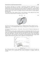
shown in Figure 1.
Fig. 1. SEM micrographs of the surface of a genuine moth eye. The compound eye of insects
consists of an arrangement of identical units, the ommatidia. Each ommatitdia itself
represents an independent optical system with its own cornea and lens to focus light on the
subjacent photoreceptor cells. a,b Compound eye of a moth build up by a microlens array of
several thousand single lenslets. c, d, The surface of a single ommatidia is equipped with a
ne nanoscopic array of protuberances. A detailed overview of structural properties for
different butterfly species can be found in literature (Stavenga et al. 2006).
Since the distance between the pillars is sufficiently small, the structure cannot be resolved
by incident light. Transition between the air-material interface thus appears as a continuous
boundary with the effect of decreased reflection and improved transmittance of all light
with a wavelength larger than the spacing period. The “Moth-eye” approach has thereby an
advantage compared to state-of-the-art antireflective coatings: Common single- and multi-
layer configurations are only applicable within a small wavelength range and near to
normal incidence of light. “Moth-eye”-structured surfaces, in contrast, show reduced and
angle-independent reflectance over a broad spectral bandwidth (Clapham et al. 1973).
In this chapter we want to discuss the physical origin of these exceptional properties and
how they can be transferred to optical functional materials. We used metallic nanoparticles
as a lithographic mask to generate a quasi-hexagonal pattern of hollow, pillar-like
protuberances into glass and fused silica substrates. We report on a combination of self-
assembly based nanotechnology and reactive ion etching as a cost-effective and
straightforward way for the fabrication of moth-eye inspired interfaces fully integrated in
the optical material itself. The structures were found to exhibit broadband antireflective
properties ranging from deep-ultraviolet to infrared light at oblique angles of incidence
(Lohmueller et al. 2008b).
2. Theoretical Considerations
According to their complexity antireection coatings can be classied by two basic models.
Reduced reflectance can either be achieved by a homogeneous single-layer or digital type
coating or by a more complex inhomogeneous multilayer configuration or gradual profile
pattern respectively, that provides a gradual refractive index transition at the air/material
interface (Dobrowolski et al. 2002).In the simplest case, a single homogeneous layer with a
refractive index n will suppress reflectance between a substrate n
s
and air n
a
for normal
incidence of light and an optical thickness of /4, if the constraint n = (n
s
n
a
)
0.5
is fulfilled.
The demand for /4 thickness is based on both effects, the optical path difference and also
the phase change at the low-to-high refractive index interface. It is important to point out
that such configurations are always limited to a single wavelength.
An improvement is achieved by the introduction of multilayer systems which show an
increased but still limited spectral bandwidth and also allow only a narrow variation of the
incidence angle. Further optimizations are possible by using gradient optical coatings which
show broadband antireflective characteristics for omnidirectional incidence of light (Poitras
et al. 2004).The first theoretical description of this characteristic was published by J. S.
Rayleigh in 1880, who mathematically demonstrated the broadband antireflection properties
of graded-refractive index layers (Rayleigh 1880). For a discontinuous boundary the
reflection coefficient at the interface of two media can be expressed as (Wilson et al. 1982)
2
2121
)]/()[( nnnnR
(1)
where n
1
and n
2
are the refractive indices. For a series of refractive indices, the total
reflectance is a result of the interference of all reflections at each incremental step along the
gradient. Each reflection has a different phase, as they come from a different depth of the
substrate. The overall reflectance will therefore be suppressed, if the height of the
antireflective structure equals to /2 and all phases are present.
In case of the “Moth eye” surface, the quasi periodical structure of the protuberances is
characterized by a lateral period which is much smaller than the optical wavelength. The
structure thus acts as a diffraction grating where only the zeroth order is allowed to
propagate and all other orders are evanescent. The “moth eye” cornea is optically equivalent
ImprovedPropertiesofOpticalSurfacesbyFollowingtheExampleofthe“MothEye” 453
address manufacturing demands for high-resolution processing (Chiu et al. 1997; Holmes et
al. 1997). Coatings in this spectral range are difficult to implement, extremely expensive, and
only a limited number of materials meet the optical requirements (Ullmann et al. 2000;
Dobrowolski et al. 2002; Kikuta et al. 2003; Kaiser 2007).
“Moth eye” surfaces may offer an intriguing solution for these problems: They were first
discovered by Bernhard (Bernhard 1967), who proposed that the function of these ‘nipple
arrays’ might be the suppression of light reflection from the eye of the insect in order to
avoid fatal consequences for the moth. The origin of these antireflective properties emerge
from a gradation of the refractive index between air and the cornea surface (Clapham et al.
1973; Wilson et al. 1982). SEM micrographs of the surface structure of a genuine moth are
shown in Figure 1.
Fig. 1. SEM micrographs of the surface of a genuine moth eye. The compound eye of insects
consists of an arrangement of identical units, the ommatidia. Each ommatitdia itself
represents an independent optical system with its own cornea and lens to focus light on the
subjacent photoreceptor cells. a,b Compound eye of a moth build up by a microlens array of
several thousand single lenslets. c, d, The surface of a single ommatidia is equipped with a
ne nanoscopic array of protuberances. A detailed overview of structural properties for
different butterfly species can be found in literature (Stavenga et al. 2006).
Since the distance between the pillars is sufficiently small, the structure cannot be resolved
by incident light. Transition between the air-material interface thus appears as a continuous
boundary with the effect of decreased reflection and improved transmittance of all light
with a wavelength larger than the spacing period. The “Moth-eye” approach has thereby an
advantage compared to state-of-the-art antireflective coatings: Common single- and multi-
layer configurations are only applicable within a small wavelength range and near to
normal incidence of light. “Moth-eye”-structured surfaces, in contrast, show reduced and
angle-independent reflectance over a broad spectral bandwidth (Clapham et al. 1973).
In this chapter we want to discuss the physical origin of these exceptional properties and
how they can be transferred to optical functional materials. We used metallic nanoparticles
as a lithographic mask to generate a quasi-hexagonal pattern of hollow, pillar-like
protuberances into glass and fused silica substrates. We report on a combination of self-
assembly based nanotechnology and reactive ion etching as a cost-effective and
straightforward way for the fabrication of moth-eye inspired interfaces fully integrated in
the optical material itself. The structures were found to exhibit broadband antireflective
properties ranging from deep-ultraviolet to infrared light at oblique angles of incidence
(Lohmueller et al. 2008b).
2. Theoretical Considerations
According to their complexity antireection coatings can be classied by two basic models.
Reduced reflectance can either be achieved by a homogeneous single-layer or digital type
coating or by a more complex inhomogeneous multilayer configuration or gradual profile
pattern respectively, that provides a gradual refractive index transition at the air/material
interface (Dobrowolski et al. 2002).In the simplest case, a single homogeneous layer with a
refractive index n will suppress reflectance between a substrate n
s
and air n
a
for normal
incidence of light and an optical thickness of /4, if the constraint n = (n
s
n
a
)
0.5
is fulfilled.
The demand for /4 thickness is based on both effects, the optical path difference and also
the phase change at the low-to-high refractive index interface. It is important to point out
that such configurations are always limited to a single wavelength.
An improvement is achieved by the introduction of multilayer systems which show an
increased but still limited spectral bandwidth and also allow only a narrow variation of the
incidence angle. Further optimizations are possible by using gradient optical coatings which
show broadband antireflective characteristics for omnidirectional incidence of light (Poitras
et al. 2004).The first theoretical description of this characteristic was published by J. S.
Rayleigh in 1880, who mathematically demonstrated the broadband antireflection properties
of graded-refractive index layers (Rayleigh 1880). For a discontinuous boundary the
reflection coefficient at the interface of two media can be expressed as (Wilson et al. 1982)
2
2121
)]/()[( nnnnR
(1)
where n
1
and n
2
are the refractive indices. For a series of refractive indices, the total
reflectance is a result of the interference of all reflections at each incremental step along the
gradient. Each reflection has a different phase, as they come from a different depth of the
substrate. The overall reflectance will therefore be suppressed, if the height of the
antireflective structure equals to /2 and all phases are present.
In case of the “Moth eye” surface, the quasi periodical structure of the protuberances is
characterized by a lateral period which is much smaller than the optical wavelength. The
structure thus acts as a diffraction grating where only the zeroth order is allowed to
propagate and all other orders are evanescent. The “moth eye” cornea is optically equivalent
Biomimetics,LearningfromNature454
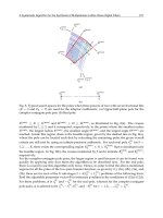
to a laterally nonstructured film with a gradual change of the refractive index in depth.
Figure 2 shows schematically the continuous increase of the physical thickness along the
antireflective structure from air to bulk.
Fig. 2. Effective refractive index prole of a genuine moth eye. The ne array of
protuberances on the lens of an insect eye has a structural period, smaller than the
wavelength of the incoming light. This special prole is leading to a gradient increase of the
material density and thus the refractive index at the air-cornea interfaces responsible for the
antireflective properties.
This model of gradual index change is also the underlying principle for various effective
medium approaches with the intention to introduce numerical methods which allow the
determination of the dielectric constant of subwavelength structured composite materials
(Lalanne et al. 2003). These approaches, however, represent only a rough approximation of
the reality with a poor account for the individual profile geometry, especially if the
structural period is infinitely smaller than the wavelength. A more exact form is given by
the effective medium theory (EMT). Considering a 1D periodic structure with a gradual
index profile, the effective refractive index n
eff
of the whole interface can be expanded in a
power series according to (Lalanne et al. 1996):
)/()/(
4)4(2)2()0(
nnnn
eff
(2)
Here, n
(0)
represents the effective index in the long-wavelength limit n
(2)
and and n
(4)
are
dimensionless coefficients depending on the structural geometry. / denotes the period-
to-wavelength ratio between the grating period of the 1D profile and the respective
wavelength. While closed-form expressions like equation (2) are feasible up to the fourth
order, an exact expression of n
eff
for 2D periodic structures, like the moth eye, has not been
achieved.
Alternatively, rigorous coupled wave analysis (RCWA), represents a method for the
numerical calculation and simulation of light waves, as they are propagating in periodic
media. The RCWA thereby represents an approximation of the Maxwell Equations
(Moharam et al. 1981). For RCWA, the geometry of a periodic pattern is divided into a define
number of incremental optical layers. This stack region represents a transition between two
semi-infinite regions such as air and the substrate. The light propagation is now calculated
by the interaction of the incoming electromagnetic field with the layer stack where
especially mutual interdependency has to be taken into account. The surface profile of a
nanopatterned optical interface can thus be modeled by dividing the structure in a
sufficiently small number of stack layers where each layer has a higher filling factor (and a
higher optical thickness, respectively) than the previous one. The RCWA approach can be
extended to accurately calculate the optimum surface-relief profile with respect to the
refractive index of the material. Southwell et al. showed that the side-walls of a pyramid-like
gradient profile would have an optimum shape (and thus optimum antireflective
properties), for a fifth-order (quintic) functional dependence of the refractive index on the
optical thickness (Southwell 1983; Southwell 1991):
)61510)(1(
543
uuunnn
ss
(3)
where u denotes the normalized optical thickness of the material ranging from zero at the
dense substrate to unity at the air/substrate interface. The optimum slope of the pyramid
sidewalls is thereby depending on the refractive index of the medium. Calculating the
quintic surface profile reveals that curved, rather than flat-sided pyramids result in an
index-matching layer with optimum antireflective properties at dielectric interfaces
(Southwell 1991).
3. Subwavelength Structured Optical Interfaces
3.1 Fabrication of Artificial “Moth Eye” Structures
Different techniques such as e-beam writing (Kanamori et al. 1999; Kanamori et al. 2000;
Toyota et al. 2001), mask lithography (Motamedi et al. 1993), and Interference Lithography
(Gombert et al. 1998) have been applied to realize master structures for sub-wavelength
structured gratings. To avoid scattering from the optical interface, the structural dimensions
have to be smaller than the wavelength of the incoming light ('lower wavelength limit')
(Wilson et al. 1982; Southwell 1991; Dobrowolski et al. 2002). For UV and DUV applications,
very small feature sizes below 200 nm are required. At the same time, the overall reflectance
is a function of the AR-layer thickness d and the wavelength (Rayleigh 1880). For a graded-
index transition, substantial anti-reflection is obtained, if the ratio d/ is about 0.4 or higher
(Wilson et al. 1982; Lalanne et al. 2003). Thus, for optimum anti-reflection conditions in the
DUV region the height of the structure should be at least 100 nm. In this size range,
conventional fabrication technologies suffer from being time-consuming, expensive and
rather complicated. Moreover, processing of non-planar substrates like lenses, especially
with a small radius of curvature is challenging. An alternative is offered by self-assembly
based methods. Porous alumina membranes (Kanamori et al. 2001) or block copolymer
layers were used in combination with subsequent dry-etching (Park et al. 1997; Cao et al.
2003) (Asakawa et al. 2002). In the latter example, the etch selectivity between acrylic and
aromatic polymer components results in a surface topography of the underlying material.
Structure depths between 8 and 30 nm have been reported in silicon, too thin to obtain a
substantial anti-reflective effect. Alternative approaches like porous sol-gel (Thomas 1992),
ImprovedPropertiesofOpticalSurfacesbyFollowingtheExampleofthe“MothEye” 455
to a laterally nonstructured film with a gradual change of the refractive index in depth.
Figure 2 shows schematically the continuous increase of the physical thickness along the
antireflective structure from air to bulk.
Fig. 2. Effective refractive index prole of a genuine moth eye. The ne array of
protuberances on the lens of an insect eye has a structural period, smaller than the
wavelength of the incoming light. This special prole is leading to a gradient increase of the
material density and thus the refractive index at the air-cornea interfaces responsible for the
antireflective properties.
This model of gradual index change is also the underlying principle for various effective
medium approaches with the intention to introduce numerical methods which allow the
determination of the dielectric constant of subwavelength structured composite materials
(Lalanne et al. 2003). These approaches, however, represent only a rough approximation of
the reality with a poor account for the individual profile geometry, especially if the
structural period is infinitely smaller than the wavelength. A more exact form is given by
the effective medium theory (EMT). Considering a 1D periodic structure with a gradual
index profile, the effective refractive index n
eff
of the whole interface can be expanded in a
power series according to (Lalanne et al. 1996):
)/()/(
4)4(2)2()0(
nnnn
eff
(2)
Here, n
(0)
represents the effective index in the long-wavelength limit n
(2)
and and n
(4)
are
dimensionless coefficients depending on the structural geometry. / denotes the period-
to-wavelength ratio between the grating period of the 1D profile and the respective
wavelength. While closed-form expressions like equation (2) are feasible up to the fourth
order, an exact expression of n
eff
for 2D periodic structures, like the moth eye, has not been
achieved.
Alternatively, rigorous coupled wave analysis (RCWA), represents a method for the
numerical calculation and simulation of light waves, as they are propagating in periodic
media. The RCWA thereby represents an approximation of the Maxwell Equations
(Moharam et al. 1981). For RCWA, the geometry of a periodic pattern is divided into a define
number of incremental optical layers. This stack region represents a transition between two
semi-infinite regions such as air and the substrate. The light propagation is now calculated
by the interaction of the incoming electromagnetic field with the layer stack where
especially mutual interdependency has to be taken into account. The surface profile of a
nanopatterned optical interface can thus be modeled by dividing the structure in a
sufficiently small number of stack layers where each layer has a higher filling factor (and a
higher optical thickness, respectively) than the previous one. The RCWA approach can be
extended to accurately calculate the optimum surface-relief profile with respect to the
refractive index of the material. Southwell et al. showed that the side-walls of a pyramid-like
gradient profile would have an optimum shape (and thus optimum antireflective
properties), for a fifth-order (quintic) functional dependence of the refractive index on the
optical thickness (Southwell 1983; Southwell 1991):
)61510)(1(
543
uuunnn
ss
(3)
where u denotes the normalized optical thickness of the material ranging from zero at the
dense substrate to unity at the air/substrate interface. The optimum slope of the pyramid
sidewalls is thereby depending on the refractive index of the medium. Calculating the
quintic surface profile reveals that curved, rather than flat-sided pyramids result in an
index-matching layer with optimum antireflective properties at dielectric interfaces
(Southwell 1991).
3. Subwavelength Structured Optical Interfaces
3.1 Fabrication of Artificial “Moth Eye” Structures
Different techniques such as e-beam writing (Kanamori et al. 1999; Kanamori et al. 2000;
Toyota et al. 2001), mask lithography (Motamedi et al. 1993), and Interference Lithography
(Gombert et al. 1998) have been applied to realize master structures for sub-wavelength
structured gratings. To avoid scattering from the optical interface, the structural dimensions
have to be smaller than the wavelength of the incoming light ('lower wavelength limit')
(Wilson et al. 1982; Southwell 1991; Dobrowolski et al. 2002). For UV and DUV applications,
very small feature sizes below 200 nm are required. At the same time, the overall reflectance
is a function of the AR-layer thickness d and the wavelength (Rayleigh 1880). For a graded-
index transition, substantial anti-reflection is obtained, if the ratio d/ is about 0.4 or higher
(Wilson et al. 1982; Lalanne et al. 2003). Thus, for optimum anti-reflection conditions in the
DUV region the height of the structure should be at least 100 nm. In this size range,
conventional fabrication technologies suffer from being time-consuming, expensive and
rather complicated. Moreover, processing of non-planar substrates like lenses, especially
with a small radius of curvature is challenging. An alternative is offered by self-assembly
based methods. Porous alumina membranes (Kanamori et al. 2001) or block copolymer
layers were used in combination with subsequent dry-etching (Park et al. 1997; Cao et al.
2003) (Asakawa et al. 2002). In the latter example, the etch selectivity between acrylic and
aromatic polymer components results in a surface topography of the underlying material.
Structure depths between 8 and 30 nm have been reported in silicon, too thin to obtain a
substantial anti-reflective effect. Alternative approaches like porous sol-gel (Thomas 1992),
Biomimetics,LearningfromNature456
and optical polymer thin film coatings (Walheim et al. 1999; Ibn-Elhaj et al. 2001) are not
useful for UV applications.
Colloidal monolayers of SiO
2
and polystyrene spheres have also been used in a combination
with reactive ion etching (RIE) to lower the substrate reflectance (Nositschka et al. 2003)
(Cheung et al. 2006) but the fabrication of small nanostructures below 200 nm covering large
surface areas is challenging. An alternative route is offered by rough metal films or colloidal
gold particles as masking material (Lewis et al. 1998) (Lewis et al. 1999; Seeger et al. 1999;
Haupt et al. 2002). The etch mask in these examples is placed on top of silicon wafers by
either sputter coating of metal islands or random deposition of colloidal gold particles out of
solution. Stochastic relief structures with a spatial resolution smaller than 100 nm have been
realized but both methods do not allow control of structural parameters such as feature size
and spacing.
We applied Block Copolymer Micelle Nanolithography (BCML) in order to create extended
and highly ordered arrays of gold nanoparticles on optical functional materials like fused
silica and glass by means of pure self assembly (Spatz et al. 2000; Glass et al. 2003).
Polystyrene-block-poly(2)-vinylpyridine, (PS-b-P2VP) diblock copolymers were dissolved in
toluene forming uniform spherical micelles. Tetrachloroaurate, HAuCl
4
was added to the
solution with a stoichiometric loading parameter defined as L = n[Me]/n[P2VP] (Me = metal
salt), in order to neutralize the vinylpyridine block, which mainly represents the micellar
core. After stirring for 24 h, all metal salt is dissolved. Glass cover slips (n = 1,52) and fused
silica wafers (n = 1,46) are immersed into solution. During the retraction, a self-assembled
monolayer of metal salt loaded micelles is formed on top of the substrate driven by the
evaporation of the solvent. Dipping the substrate has a certain advantage over other
methods in that it enables a fast and homogeneous coating of plane as well as curved
substrates like e.g. lenses with high reproducibility. BCML has no special requirements for
the substrate composition besides it has to be resistant to the solvent. The polymer matrix is
entirely removed by hydrogen plasma treatment of the sample leaving a template of
hexagonally ordered gold particles on the surface. Various materials such as glass, silica,
GaAs, mica as well as saphire or diamond can be completely structured with nanosized
particles over a large area >> cm
2
within minutes. Advantageous of this technique is that the
interparticle distance and the average colloidal diameter can be adjusted independently of one
another enabling particle spacing between 15 and 250 nm and a precise control of the particle size
(Lohmueller et al. 2008a). These particles act as a shadow mask for subsequent reactive ion
etching (RIE) leading to a surface texture with anti-reflective properties (Figure 3).
We realized antireflective nanostructures on glass and on both, plane and biconvex fused
silica surfaces. The structural period was set to 100 nm with a structure depth between 60
nm and 120 nm.
The gold nanoparticles are functioning as a protective resist during the etching process due
to their high stability against the plasma treatment compared to the underlying material.
Since the RIE process represents an unselective physical ion bombardment of the sample,
the gold particles are continuously reduced in size until they are used up completely. From
that moment on, the whole surface is uniformly etched and the structure is destroyed.
Artificial moth eye structures were prepared on glass and fused silica as shown in Figure 4.
Fig. 3. Schematic of the fabrication process. a, The substrate is immersed into a toluene
solution of metal salt loaded micelles. During retraction, a micellar monolayer self-
assembles on top of the substrate driven by capillary forces due to the evaporation of the
solvent. The polymer matrix is removed entirely by hydrogen plasma treatment and results
in the deposition of an extended array of elemental gold particles on top of the substrate.
Gold nanoparticles act as an efficient mask for etching hollow cone-like pillars into the
underlying silica support by Reactive Ion Etching (RIE). b, The distance between the
nanoparticles can be controlled over several hundreds of nanometers. The hexatic
arrangement of the particles on the surface is similar to the orientation of the protuberances
found on the eye of moths.
Fig. 4. “Moth-eye” structured glass cover slips and fused silica samples. a, High
magnification micrograph showing the triangular shape of the glass cones. b, Side-view
image of the pillar array measured with a tilt angle of 45
The nanostructure profiles were different depending on the substrate material. On the glass-
cover slips, the process resulted in a homogeneously patterned array of nano-cones with a
diameter of 80 ± 5 nm at the base and a structural depth of app. 60 nm, representing the
effective thickness of the antireflective layer. The sidewalls of the cones had an inclination
angle of app. = 60°. The triangular shape found on top of the normal glass is a consequence
ImprovedPropertiesofOpticalSurfacesbyFollowingtheExampleofthe“MothEye” 457
and optical polymer thin film coatings (Walheim et al. 1999; Ibn-Elhaj et al. 2001) are not
useful for UV applications.
Colloidal monolayers of SiO
2
and polystyrene spheres have also been used in a combination
with reactive ion etching (RIE) to lower the substrate reflectance (Nositschka et al. 2003)
(Cheung et al. 2006) but the fabrication of small nanostructures below 200 nm covering large
surface areas is challenging. An alternative route is offered by rough metal films or colloidal
gold particles as masking material (Lewis et al. 1998) (Lewis et al. 1999; Seeger et al. 1999;
Haupt et al. 2002). The etch mask in these examples is placed on top of silicon wafers by
either sputter coating of metal islands or random deposition of colloidal gold particles out of
solution. Stochastic relief structures with a spatial resolution smaller than 100 nm have been
realized but both methods do not allow control of structural parameters such as feature size
and spacing.
We applied Block Copolymer Micelle Nanolithography (BCML) in order to create extended
and highly ordered arrays of gold nanoparticles on optical functional materials like fused
silica and glass by means of pure self assembly (Spatz et al. 2000; Glass et al. 2003).
Polystyrene-block-poly(2)-vinylpyridine, (PS-b-P2VP) diblock copolymers were dissolved in
toluene forming uniform spherical micelles. Tetrachloroaurate, HAuCl
4
was added to the
solution with a stoichiometric loading parameter defined as L = n[Me]/n[P2VP] (Me = metal
salt), in order to neutralize the vinylpyridine block, which mainly represents the micellar
core. After stirring for 24 h, all metal salt is dissolved. Glass cover slips (n = 1,52) and fused
silica wafers (n = 1,46) are immersed into solution. During the retraction, a self-assembled
monolayer of metal salt loaded micelles is formed on top of the substrate driven by the
evaporation of the solvent. Dipping the substrate has a certain advantage over other
methods in that it enables a fast and homogeneous coating of plane as well as curved
substrates like e.g. lenses with high reproducibility. BCML has no special requirements for
the substrate composition besides it has to be resistant to the solvent. The polymer matrix is
entirely removed by hydrogen plasma treatment of the sample leaving a template of
hexagonally ordered gold particles on the surface. Various materials such as glass, silica,
GaAs, mica as well as saphire or diamond can be completely structured with nanosized
particles over a large area >> cm
2
within minutes. Advantageous of this technique is that the
interparticle distance and the average colloidal diameter can be adjusted independently of one
another enabling particle spacing between 15 and 250 nm and a precise control of the particle size
(Lohmueller et al. 2008a). These particles act as a shadow mask for subsequent reactive ion
etching (RIE) leading to a surface texture with anti-reflective properties (Figure 3).
We realized antireflective nanostructures on glass and on both, plane and biconvex fused
silica surfaces. The structural period was set to 100 nm with a structure depth between 60
nm and 120 nm.
The gold nanoparticles are functioning as a protective resist during the etching process due
to their high stability against the plasma treatment compared to the underlying material.
Since the RIE process represents an unselective physical ion bombardment of the sample,
the gold particles are continuously reduced in size until they are used up completely. From
that moment on, the whole surface is uniformly etched and the structure is destroyed.
Artificial moth eye structures were prepared on glass and fused silica as shown in Figure 4.
Fig. 3. Schematic of the fabrication process. a, The substrate is immersed into a toluene
solution of metal salt loaded micelles. During retraction, a micellar monolayer self-
assembles on top of the substrate driven by capillary forces due to the evaporation of the
solvent. The polymer matrix is removed entirely by hydrogen plasma treatment and results
in the deposition of an extended array of elemental gold particles on top of the substrate.
Gold nanoparticles act as an efficient mask for etching hollow cone-like pillars into the
underlying silica support by Reactive Ion Etching (RIE). b, The distance between the
nanoparticles can be controlled over several hundreds of nanometers. The hexatic
arrangement of the particles on the surface is similar to the orientation of the protuberances
found on the eye of moths.
Fig. 4. “Moth-eye” structured glass cover slips and fused silica samples. a, High
magnification micrograph showing the triangular shape of the glass cones. b, Side-view
image of the pillar array measured with a tilt angle of 45
The nanostructure profiles were different depending on the substrate material. On the glass-
cover slips, the process resulted in a homogeneously patterned array of nano-cones with a
diameter of 80 ± 5 nm at the base and a structural depth of app. 60 nm, representing the
effective thickness of the antireflective layer. The sidewalls of the cones had an inclination
angle of app. = 60°. The triangular shape found on top of the normal glass is a consequence
Biomimetics,LearningfromNature458
of a mixed isotropic-anisotropic etching at a moderate plasma power with an etch rate of
app. 10 nm/min. According to theory, the optimum quintic profile for glass corresponds to
the form of a nearly flat sided pyramid (Southwell 1991). Therefore, the process values were
elaborated in order to generate an array of glass cones, which continuously converge
towards the bottom. The sharp cone tips are indicating the optimum etching time. The
samples were processed until the colloidal metal spheres were completely removed. For
longer sample processing or higher RF power, the tips of the structure are blunted and the
height is reduced. In both cases the optical performance declines considerably. ). For fused
silica, a rather anisotropic etch profile was observed with an etch rate of 30 nm/min, three
times higher than in the case of normal glass. Instead of sloping side walls, the structure had
a vertical, pillar-like shape with a diameter of 60 ± 8 nm and a lateral spacing of 114 ± 3 nm
(center to center) respectively. The different result can be explained by the lower resistance
of the fused silica against the plasma treatment compared to normal glass. The height of the
structure was measured to be 120 nm, which corresponds to the effective thickness of the
antireflective layer (Figure 5).
Fig. 5. a, 60 side-view SE-micrograph of the gold nanoparticles used as an etch mask.
Comparison between a cross section of the cornea of a b, moth eye and the c, artificial moth
eye profile in fused silica. Focused Ion Beam (FIB) cross section through the antireflective
structure. The pillars have a diameter of 60±4 nm and a lateral spacing of 110±7 nm (center
to center), respectively. The height of the structure was measured to be 120±5 nm which
corresponds to the effective thickness of the antireflective layer. A cone-type hole is etched
into each pillar tip to approximately half of the pillar height. e, Schematic displaying the
fabrication of hollow cone-like pillars during the reactive ion etching process in the presence
of gold nanoparticles.
Remarkably, the tips of the pillars are hollow and pores are formed at the spots where the
gold particle had been placed originally. A hole is etched into each pillar tip to app. half of
the pillar height. This is caused by a electrostatic sheath ("Debye Sheath") (Langmuir 1923;
Hull et al. 1929), formed above the sample during the plasma process (Figure 5 d). In the
sheath region a strong electric field is generated perpendicular to the surface. The presence
of electrical conductive gold clusters on top of the insulating material, however, causes a
sheath distortion in the vicinity of the conductor/insulator interface (Kim et al. 2004). The
reactive ions of the plasma are thereby focused to the contact area of the metallic
nanoparticles with the underlying fused silica substrate. This causes a depletion of the
plasma-generated reactive ion concentration around the metal islands. As a consequence,
the particles act as an etching mask for processing hollow, cone-like pillars oriented
perpendicular to the substrate. During the etching process, the particles sink into the
material and the particle diameter continuously decreases until they are completely used up.
The outer diameter of the pillars is larger than the nanoparticles due to depletion of ion
concentration, while the inner diameter of the hollow structure reflects the original particle
size. As mentioned earlier, a gradual increase of material from air to bulk is responsible for
the substrate's anti-reflection properties (Moharam et al. 1981) (Kikuta et al. 2003).
Consequently, the partly hollow, cone-type pillars are expected to improve the anti-
reflective quality of the structure.
3.2 Optical Characterization
Different sub-wavelength profiles were obtained depending on the substrate material
showing significant anti-reflective properties over a broad wavelength range from the deep
UV up to the IR region. The optical properties of the fabricated samples were investigated
by wavelength dependent transmission measurements. The incidence direction of the probe
beam was oriented perpendicular to the surface. An unstructured substrate was measured
in each case as a reference. For quantification, the reference measurement was also used to
subtract the reflex from the backside of the single-sided structured samples. Figure 6 shows
the measured transmission in dependence on the wavelength for glass and fused silica.
Fig. 6. Transmittance of an untreated and sntireflective structured substrate of a, glass and b,
fused silica. Residuals of the gold particles are visible in the spectra by a minimum of the
transmission curve (red dotted line) that correlates with the maximum of the absorbance
spectra (grey line) of the plasmon resonance of the gold particles. The reflex contribution of
the sample backsides was subtracted for all spectra.
ImprovedPropertiesofOpticalSurfacesbyFollowingtheExampleofthe“MothEye” 459
of a mixed isotropic-anisotropic etching at a moderate plasma power with an etch rate of
app. 10 nm/min. According to theory, the optimum quintic profile for glass corresponds to
the form of a nearly flat sided pyramid (Southwell 1991). Therefore, the process values were
elaborated in order to generate an array of glass cones, which continuously converge
towards the bottom. The sharp cone tips are indicating the optimum etching time. The
samples were processed until the colloidal metal spheres were completely removed. For
longer sample processing or higher RF power, the tips of the structure are blunted and the
height is reduced. In both cases the optical performance declines considerably. ). For fused
silica, a rather anisotropic etch profile was observed with an etch rate of 30 nm/min, three
times higher than in the case of normal glass. Instead of sloping side walls, the structure had
a vertical, pillar-like shape with a diameter of 60 ± 8 nm and a lateral spacing of 114 ± 3 nm
(center to center) respectively. The different result can be explained by the lower resistance
of the fused silica against the plasma treatment compared to normal glass. The height of the
structure was measured to be 120 nm, which corresponds to the effective thickness of the
antireflective layer (Figure 5).
Fig. 5. a, 60 side-view SE-micrograph of the gold nanoparticles used as an etch mask.
Comparison between a cross section of the cornea of a b, moth eye and the c, artificial moth
eye profile in fused silica. Focused Ion Beam (FIB) cross section through the antireflective
structure. The pillars have a diameter of 60±4 nm and a lateral spacing of 110±7 nm (center
to center), respectively. The height of the structure was measured to be 120±5 nm which
corresponds to the effective thickness of the antireflective layer. A cone-type hole is etched
into each pillar tip to approximately half of the pillar height. e, Schematic displaying the
fabrication of hollow cone-like pillars during the reactive ion etching process in the presence
of gold nanoparticles.
Remarkably, the tips of the pillars are hollow and pores are formed at the spots where the
gold particle had been placed originally. A hole is etched into each pillar tip to app. half of
the pillar height. This is caused by a electrostatic sheath ("Debye Sheath") (Langmuir 1923;
Hull et al. 1929), formed above the sample during the plasma process (Figure 5 d). In the
sheath region a strong electric field is generated perpendicular to the surface. The presence
of electrical conductive gold clusters on top of the insulating material, however, causes a
sheath distortion in the vicinity of the conductor/insulator interface (Kim et al. 2004). The
reactive ions of the plasma are thereby focused to the contact area of the metallic
nanoparticles with the underlying fused silica substrate. This causes a depletion of the
plasma-generated reactive ion concentration around the metal islands. As a consequence,
the particles act as an etching mask for processing hollow, cone-like pillars oriented
perpendicular to the substrate. During the etching process, the particles sink into the
material and the particle diameter continuously decreases until they are completely used up.
The outer diameter of the pillars is larger than the nanoparticles due to depletion of ion
concentration, while the inner diameter of the hollow structure reflects the original particle
size. As mentioned earlier, a gradual increase of material from air to bulk is responsible for
the substrate's anti-reflection properties (Moharam et al. 1981) (Kikuta et al. 2003).
Consequently, the partly hollow, cone-type pillars are expected to improve the anti-
reflective quality of the structure.
3.2 Optical Characterization
Different sub-wavelength profiles were obtained depending on the substrate material
showing significant anti-reflective properties over a broad wavelength range from the deep
UV up to the IR region. The optical properties of the fabricated samples were investigated
by wavelength dependent transmission measurements. The incidence direction of the probe
beam was oriented perpendicular to the surface. An unstructured substrate was measured
in each case as a reference. For quantification, the reference measurement was also used to
subtract the reflex from the backside of the single-sided structured samples. Figure 6 shows
the measured transmission in dependence on the wavelength for glass and fused silica.
Fig. 6. Transmittance of an untreated and sntireflective structured substrate of a, glass and b,
fused silica. Residuals of the gold particles are visible in the spectra by a minimum of the
transmission curve (red dotted line) that correlates with the maximum of the absorbance
spectra (grey line) of the plasmon resonance of the gold particles. The reflex contribution of
the sample backsides was subtracted for all spectra.
Biomimetics,LearningfromNature460
The distinct antireflective properties are clearly observable over the whole observed spectral
region. Increased transmission of nearly 2% at a wavelength of 350 nm was detected
compared to a reference glass cover slip. Residual gold may be left over on top of the
substrate after RIE. However, if there are any remains of the particles, they are visible in the
transmission spectrum. This is shown in Figure 6 a by the curve minimum that appears
around 530 nm overlapping with the maximum of the absorbance spectra that was taken
from the same sample. After five minutes no vestiges of the gold were detectable. By an
alternate measurement of plasmon absorbance and overall transmission it is thus possible to
determine the point of time when the particles are completely used off during the RIE
process. Beside their role as plasma resist, the gold particles are thereby acting as an
indicator for the course of the experiment. The transmission efficiency for the pillar-like
structures was higher compared to the cone-shaped profile found on the glass cover slips.
The reason is the smaller height of the glass indentations of only 60 nm, where the fused
silica samples reached a structural depth of up to 120 nm. The effective thickness of the
structure is mainly responsible for the efficiency of the antireflective properties and should
therefore be in the order of half the wavelength or more. In the case of the VIS spectral
region, ideal structure depth would therefore be between 200 nm and 400 nm. The desired
parameters for an artificial moth eye design imply a structural spacing as small as possible
and a structural depth as great as possible to achieve the least reflection and highest
transmission over a broad bandwidth. The obtained pillar height, however, should show an
optimum performance for the aspired wavelength range below 300 nm. The topology of the
fused silica sample was similar to the corneal surface of a real moth.
As already mentioned, the moth eye lens shows a superior optical performance compared to
many non-natural materials, since the overall reflection is reduced, while at the same time the
transmission of light in the visible range is increased for omni-directional incidence of light.
This is in contrast to non-reflecting coatings based on compound films or unspecific surface
roughness, where diffuse scattering reduces the reflection but transmission is damped at the
same time. The optical properties of plane fused silica samples were investigated by angle
dependent reflection measurements at a particular as shown in Figure 7.
Fig. 7. Reflectance of an antireflective structured (red line) and a reference (black line)
sample as a function of incident angle. The reflex contribution of the sample backsides was
not subtracted in this case.
An increase of the total transmission was observed over a spectral range from 300 to 800 nm.
At = 400 nm the transmittance reached a maximum value of 99.3 % (Figure 6 b), while the
reflectivity of the same sample was damped to 0.7 %. Since the improved transmission is in
accordance with a reduced reflectance, it is apparent that light scattering defects or
absorption losses, which might have been introduced by the fabrication process, play, if at
all existing, a minor role. The reflection and transmission under a certain angle is dependent
on the polarization of the incoming light due to Fresnel’s law as demonstrated in Figure 8.
Fig. 8. Angle dependent transmission with polarized light. a,b,Spectral transmission of p-
ands-polarized light for different angles of incidence(black: 0; red: 15; green: 30; blue: 45)
As expected, the difference between the transmittance for p - and s - polarized light is
increasing towards larger polarization angles with a maximum dispartment at the Brewster
angle (55.4 for fused silica, n = 1.46) (Hecht 2002).
Fig. 9. Optical properties of an antireflective structured lens. a, Photograph of the processed
lens demonstrating the anti-reflective effect. The borderline between the structured (bottom)
and unstructured (top) area is indicated by the white arrow. b, Transmission spectra of the
same lens before (black line) and after (red line) processing. An increase of transmission was
observed for the DUV range from 185 to 300 nm. The improved transmission values for the
excimer laser wavelengths 193 nm (ArF) and 248 nm (KrF) are shown exemplary.
ImprovedPropertiesofOpticalSurfacesbyFollowingtheExampleofthe“MothEye” 461
The distinct antireflective properties are clearly observable over the whole observed spectral
region. Increased transmission of nearly 2% at a wavelength of 350 nm was detected
compared to a reference glass cover slip. Residual gold may be left over on top of the
substrate after RIE. However, if there are any remains of the particles, they are visible in the
transmission spectrum. This is shown in Figure 6 a by the curve minimum that appears
around 530 nm overlapping with the maximum of the absorbance spectra that was taken
from the same sample. After five minutes no vestiges of the gold were detectable. By an
alternate measurement of plasmon absorbance and overall transmission it is thus possible to
determine the point of time when the particles are completely used off during the RIE
process. Beside their role as plasma resist, the gold particles are thereby acting as an
indicator for the course of the experiment. The transmission efficiency for the pillar-like
structures was higher compared to the cone-shaped profile found on the glass cover slips.
The reason is the smaller height of the glass indentations of only 60 nm, where the fused
silica samples reached a structural depth of up to 120 nm. The effective thickness of the
structure is mainly responsible for the efficiency of the antireflective properties and should
therefore be in the order of half the wavelength or more. In the case of the VIS spectral
region, ideal structure depth would therefore be between 200 nm and 400 nm. The desired
parameters for an artificial moth eye design imply a structural spacing as small as possible
and a structural depth as great as possible to achieve the least reflection and highest
transmission over a broad bandwidth. The obtained pillar height, however, should show an
optimum performance for the aspired wavelength range below 300 nm. The topology of the
fused silica sample was similar to the corneal surface of a real moth.
As already mentioned, the moth eye lens shows a superior optical performance compared to
many non-natural materials, since the overall reflection is reduced, while at the same time the
transmission of light in the visible range is increased for omni-directional incidence of light.
This is in contrast to non-reflecting coatings based on compound films or unspecific surface
roughness, where diffuse scattering reduces the reflection but transmission is damped at the
same time. The optical properties of plane fused silica samples were investigated by angle
dependent reflection measurements at a particular as shown in Figure 7.
Fig. 7. Reflectance of an antireflective structured (red line) and a reference (black line)
sample as a function of incident angle. The reflex contribution of the sample backsides was
not subtracted in this case.
An increase of the total transmission was observed over a spectral range from 300 to 800 nm.
At = 400 nm the transmittance reached a maximum value of 99.3 % (Figure 6 b), while the
reflectivity of the same sample was damped to 0.7 %. Since the improved transmission is in
accordance with a reduced reflectance, it is apparent that light scattering defects or
absorption losses, which might have been introduced by the fabrication process, play, if at
all existing, a minor role. The reflection and transmission under a certain angle is dependent
on the polarization of the incoming light due to Fresnel’s law as demonstrated in Figure 8.
Fig. 8. Angle dependent transmission with polarized light. a,b,Spectral transmission of p-
ands-polarized light for different angles of incidence(black: 0; red: 15; green: 30; blue: 45)
As expected, the difference between the transmittance for p - and s - polarized light is
increasing towards larger polarization angles with a maximum dispartment at the Brewster
angle (55.4 for fused silica, n = 1.46) (Hecht 2002).
Fig. 9. Optical properties of an antireflective structured lens. a, Photograph of the processed
lens demonstrating the anti-reflective effect. The borderline between the structured (bottom)
and unstructured (top) area is indicated by the white arrow. b, Transmission spectra of the
same lens before (black line) and after (red line) processing. An increase of transmission was
observed for the DUV range from 185 to 300 nm. The improved transmission values for the
excimer laser wavelengths 193 nm (ArF) and 248 nm (KrF) are shown exemplary.
Biomimetics,LearningfromNature462
To demonstrate the excellent applicability of the method to non-planar optical components,
the convex side of a fused silica lens was processed and characterized by sub-300 nm
transmission measurements. The planconvex lens had a diameter of 22.4 mm and a focal
distance of 100 mm, which corresponds to a radius of curvature of 46 mm. The reduced
reflectivity in the visible light region of the structured part of the lens surface is shown in
Figure 9. More intense light reflectivity is seen above the line indicated by the white arrow
which is the border line between the nanostructured and the unstructured part of the lens
surface, whereas, the antireflective structured part of the lens appears less bright.
Transmission in the DUV range was measured between 185 and 300 nm (Figure 9b). The
performance was improved over the entire DUV spectral region, by 5 % for 193 nm and 3 %
for 248 nm at the excimer laser wavelengths of ArF and KrF, respectively. The high increase
of transmission of about 5 % therefore relate to a virtual elimination of reflection at the
modified optical interface.
3.3 Wettability of Nanostructured Interfaces
Beside the improved optical performance, a substantial change of the surface wettability
was observed for the antireflective structured fused silica samples. This observation is
advantageous, since an additional self-cleaning property of the optical interface would even
enhance its practical applicability. Contact angle measurements were performed to
investigate the hydrophopic effect of the antireflective structured fused silica interface. A
difference of the contact angle of about 100° was observed between a plain and structured
fused silica sample, which is a clear change of the surface wettability from hydrophilic to
hydrophobic as shown in Figure 10.
Fig. 10. Wetting of “Moth-eye” nanostructured fused silica samples. The contact angle for
water of a, plane and b, nanostructured fused silica samples is increased from 33 to 132.
A famous example for topology induced superhydrophobicity is the lotus effect (Neinhuis et
al. 1997). The leaves of lotus plants, although they usually grow in a swamp like, muddy
habitat, stay clean, since a certain microscopic structure and surface chemistry prevent the
leaves from being moistened. Instead of a liquid film, water droplets are formed which pick
up dirt as they roll of the leave. In contrast to the lotus leaf, no additional change of the
surface chemistry was introduced to amplify the water repellent properties. The
hydrophopicity in this case is solely a result of the special surface topology. This observation
can be explained according to the Cassie’s approach of surface wettability on rough
substrates (Cassie 1948). As shown in Figur 5 c the antireflective structure is build up by
half-hollow protuberances with steep sidewalls. Grooves between the pillars, as well as the
hollow pillar heads are leading to a strong lowering of the water-solid contact area.
Furthermore, air bubbles are trapped within the structure forming a material-air-water
composite interface. Wetting of the pillar structure is hindered, due to the steep sidewalls
and the surface tension of water resulting in a liquid meniscus between the nanoscopic
features and a high Laplace pressure. The effect of the sidewall angle and the Laplace
pressure p can be expressed according to (Patankar 2003; Xiu et al. 2007):
tan
)cos(
0
0
hR
ppp
(4)
In this equation, denotes the surface tension of water, is the contact angle of water on the
structure, R
0
is half of the width between two individual pillar sidewalls, p is the pressure
on the liquid side of the meniscus and p
0
is the atmospheric pressure. The geometry of the
structure is considered in this equation by the inclination angle perpendicular to the
surface. For steep sidewalls = 0, the Laplace equation is reduced to:
0
cos
R
p
(5)
In this state, the Laplace pressure p has its highest value for a small R
0
which results in an
increase of the water contact angle on top of the substrate.
4. Conclusion
We have demonstrated a new approach for the low-cost fabrication of antireflective
structured materials is demonstrated by utilizing the advantage of self-assembly based
nanolithography and reactive ion etching. Quasi hexagonal arrays of gold nanoparticles are
used as an etch mask for plasma processing of glass cover slips and fused silica wafers.
Cone-shaped and pillar-like protuberances with a structural period of 100 nm and a height
of 60 nm and 120 nm, respectively, have been fabricated. Anti-reflective properties of these
structures were demonstrated by transmission and reflection measurements for
wavelengths ranging from deep UV to IR for oblique angles of incidence. Applicability of
the fabrication method has been demonstrated on planconvex fused silica lenses with the
result of a substantially increased transmittance of light in the DUV spectral region between
185 and 300 nm. Beside the remarkable optical properties, these structures offer additional
advantages compared to thin-film coatings in terms of mechanical stability and durability.
“Moth eye” structured devices can be used over a broad thermal range since they are
essentially free of adhesion problems and tensile stress between the substrate and the
antireflective layer. In addition, “Moth eye” structured fused silica samples were found to
show a strong hydrophobicity caused by air that is trapped in the grooves between the
hollow pillar features and the water-material interface. Overall, the method represents a fast,
inexpensive, and very reproducible way for the fabrication of highly light-transmissive, anti-
ImprovedPropertiesofOpticalSurfacesbyFollowingtheExampleofthe“MothEye” 463
To demonstrate the excellent applicability of the method to non-planar optical components,
the convex side of a fused silica lens was processed and characterized by sub-300 nm
transmission measurements. The planconvex lens had a diameter of 22.4 mm and a focal
distance of 100 mm, which corresponds to a radius of curvature of 46 mm. The reduced
reflectivity in the visible light region of the structured part of the lens surface is shown in
Figure 9. More intense light reflectivity is seen above the line indicated by the white arrow
which is the border line between the nanostructured and the unstructured part of the lens
surface, whereas, the antireflective structured part of the lens appears less bright.
Transmission in the DUV range was measured between 185 and 300 nm (Figure 9b). The
performance was improved over the entire DUV spectral region, by 5 % for 193 nm and 3 %
for 248 nm at the excimer laser wavelengths of ArF and KrF, respectively. The high increase
of transmission of about 5 % therefore relate to a virtual elimination of reflection at the
modified optical interface.
3.3 Wettability of Nanostructured Interfaces
Beside the improved optical performance, a substantial change of the surface wettability
was observed for the antireflective structured fused silica samples. This observation is
advantageous, since an additional self-cleaning property of the optical interface would even
enhance its practical applicability. Contact angle measurements were performed to
investigate the hydrophopic effect of the antireflective structured fused silica interface. A
difference of the contact angle of about 100° was observed between a plain and structured
fused silica sample, which is a clear change of the surface wettability from hydrophilic to
hydrophobic as shown in Figure 10.
Fig. 10. Wetting of “Moth-eye” nanostructured fused silica samples. The contact angle for
water of a, plane and b, nanostructured fused silica samples is increased from 33 to 132.
A famous example for topology induced superhydrophobicity is the lotus effect (Neinhuis et
al. 1997). The leaves of lotus plants, although they usually grow in a swamp like, muddy
habitat, stay clean, since a certain microscopic structure and surface chemistry prevent the
leaves from being moistened. Instead of a liquid film, water droplets are formed which pick
up dirt as they roll of the leave. In contrast to the lotus leaf, no additional change of the
surface chemistry was introduced to amplify the water repellent properties. The
hydrophopicity in this case is solely a result of the special surface topology. This observation
can be explained according to the Cassie’s approach of surface wettability on rough
substrates (Cassie 1948). As shown in Figur 5 c the antireflective structure is build up by
half-hollow protuberances with steep sidewalls. Grooves between the pillars, as well as the
hollow pillar heads are leading to a strong lowering of the water-solid contact area.
Furthermore, air bubbles are trapped within the structure forming a material-air-water
composite interface. Wetting of the pillar structure is hindered, due to the steep sidewalls
and the surface tension of water resulting in a liquid meniscus between the nanoscopic
features and a high Laplace pressure. The effect of the sidewall angle and the Laplace
pressure p can be expressed according to (Patankar 2003; Xiu et al. 2007):
tan
)cos(
0
0
hR
ppp
(4)
In this equation, denotes the surface tension of water, is the contact angle of water on the
structure, R
0
is half of the width between two individual pillar sidewalls, p is the pressure
on the liquid side of the meniscus and p
0
is the atmospheric pressure. The geometry of the
structure is considered in this equation by the inclination angle perpendicular to the
surface. For steep sidewalls = 0, the Laplace equation is reduced to:
0
cos
R
p
(5)
In this state, the Laplace pressure p has its highest value for a small R
0
which results in an
increase of the water contact angle on top of the substrate.
4. Conclusion
We have demonstrated a new approach for the low-cost fabrication of antireflective
structured materials is demonstrated by utilizing the advantage of self-assembly based
nanolithography and reactive ion etching. Quasi hexagonal arrays of gold nanoparticles are
used as an etch mask for plasma processing of glass cover slips and fused silica wafers.
Cone-shaped and pillar-like protuberances with a structural period of 100 nm and a height
of 60 nm and 120 nm, respectively, have been fabricated. Anti-reflective properties of these
structures were demonstrated by transmission and reflection measurements for
wavelengths ranging from deep UV to IR for oblique angles of incidence. Applicability of
the fabrication method has been demonstrated on planconvex fused silica lenses with the
result of a substantially increased transmittance of light in the DUV spectral region between
185 and 300 nm. Beside the remarkable optical properties, these structures offer additional
advantages compared to thin-film coatings in terms of mechanical stability and durability.
“Moth eye” structured devices can be used over a broad thermal range since they are
essentially free of adhesion problems and tensile stress between the substrate and the
antireflective layer. In addition, “Moth eye” structured fused silica samples were found to
show a strong hydrophobicity caused by air that is trapped in the grooves between the
hollow pillar features and the water-material interface. Overall, the method represents a fast,
inexpensive, and very reproducible way for the fabrication of highly light-transmissive, anti-
Biomimetics,LearningfromNature464
reflective optical materials to be used for display panels, projection optics and heat-
generating microscopic and excimer laser applications.
5. References
Asakawa, K. and T. Hiraoka (2002). "Nanopatterning with microdomains of Block
Copolymers using reactive-Ion etching selectivity." Japanese Journal of Applied
Physics 41: 6112-6118.
Bernhard, C. G. (1967). "Structural and functional adaptation in a visual system." Endeavour
26: 79-84.
Cao, L., J. A. Massey, et al. (2003). "Reactive ion etching of cylindrical polyferrocenylsilane
block copolymer micelles: Fabrication of ceramic nanolines on semiconducting
substrates." Advanced Functional Materials
13: 271-276.
Cassie, A. B. D. (1948). "Contact angles." Discussions of the Faraday Society
33: 11-16.
Cheung, C. L., R. J. Nikoli, et al. (2006). "Fabrication of nanopillars by nanosphere
lithography." Nanotechnology
17: 1339–1343.
Chiu, G. L. T. and J. M. Shaw (1997). "Optical Lithography: Introduction." IBM Journal of
Research and Development 41(1/2).
Clapham, P. B. and M. C. Hutley (1973). "Reduction of lens reflection by the moth eye
principle." Nature 244(3): 281-282.
Dobrowolski, J. A., D. Poitras, et al. (2002). "Toward perfect antireflection coatings:
numerical investigation." Applied Optics
41(16): 3075-3083.
Glass, R., M. Moeller, et al. (2003). "Block copolymer micelle nanolithography."
Nanotechnology
14: 1153-1160.
Gombert, A., K. Rose, et al. (1998). "Antireflective submicrometer surface-relief gratings for
solar applications." Solar Energy Materials & Solar Cells
54: 333-342.
Haupt, M., S. Miller, et al. (2002). "Semiconductor nanostructures defined with self-
organizing polymers." Journal of Applied Physics
91: 6057-6059.
Hecht, E. (2002). Optics, Addison Wesley.
Holmes, S. J., P. H. Mtchell, et al. (1997). "Manufacturing with DUV lithography." IBM
Journal of Research and Development 41.
Hull, A. W. and I. Langmuir (1929). "Control of an arc discharge by means of an grid." PNAS
15(3): 218-225.
Ibn-Elhaj, M. and M. Schadt (2001). "Optical polymer thin films with isotropic and
anisotropic nano-corrugated surface topologies." Nature
410(6830): 796-799.
Kaiser, N. (2007). "Old rules useful to the designer of optical coatings." Vakuum in
Forschung und Praxis 19(4): 17–23.
Kanamori, Y., K. Hane, et al. (2001). "100 nm eriod silicon antireflection structures fabricated
using a porous alumina membrane mask." Applied Physics Letters
78(142-143).
Kanamori, Y., H. Kikuta, et al. (2000). "Broadband antireflection gratings for glass substrates
fabricated by fast atom beam etching." Japanese Journal of Applied Physics
39:
L735-L737.
Kanamori, Y., M. Sasaki, et al. (1999). "Antireflection gratings fabricated upon silicon
substrates." Optics Letters
24: 1422-1424.
Kikuta, H., H. Toyota, et al. (2003). "Optical elements with subwavelength structured
surfaces." Optical Review
10(2): 63-73.
Kim, D. and D. J. Economou (2004). "Simulation of a two-dimensional sheath over a flat
insulator-conductor interface on a radio-frequency biased electrode in a high-
density plasma." Journal of Applied Physics 95: 3311-3318.
Lalanne, P. and M. Hutley (2003). Encyclopedia of Optical Engineering - Artificial Media
Optical Properties—Subwavelength Scale, Marcel Dekker, Inc.
Lalanne, P. and D. Lemercier-Lalanne (1996). "On the effective medium theory of
subwavelength periodic structures." Journal of Modern Optics 43(10): 2063-2086.
Langmuir, I. (1923). "Positive ion currents from the positive column of mercury arcs."
Science 58(1502): 290-291.
Lewis, P. A. and H. Ahmed (1999). "Patterning of silicon nanopillars formed with a colloidal
gold etch mask." Journal of Vaccum Science and Technology B 17: 3239-3243.
Lewis, P. A., H. Ahmed, et al. (1998). "Silicon nanopillars formed with gold colloidal particle
masking." Journal of Vaccum Science and Technology B 16(6): 2938-2941.
Lohmueller, T., E. Bock, et al. (2008a). "Synthesis of quasi hexagonal ordered arrays of
metallic nanoparticles with tuneable particle size." Advanced Materials 20(12):
2297-2302
Lohmueller, T., M. Helgert, et al. (2008b). "Biomimetic Interfaces for high-performance
optics in the Deep-UV light range." Nano Letters 8(5): 1429-1433
Moharam, M. G. and T. K. Gaylord (1981). "Rigorous coupled-wave analysis of grating
diffraction." Journal of the Optical Society of America A: Optics, Image Science, and
Vision 71: 811-818.
Motamedi, M. E., W. H. Southwell, et al. (1993). "Antireflection surfaces in silicon using
binary optics technology." Applied Optics 31(22): 4371-4376.
Neinhuis, C. and W. Barthlott (1997). "Characterization and distribution of water repellent,
self-cleaning plant surfaces." Annals of Botany 6: 667-677.
Nositschka, W. A., C. Beneking, et al. (2003). "Texturisation of multicrystalline silicon wafers
for solar cells by reactive ion etching through colloidal masks." Solar Energy
Materials & Solar Cells 76: 155–166.
Park, M., C. Harrison, et al. (1997). "Block Copolymer Lithography: Periodic arrays of ~10
11
holes in 1 square centimeter." Science 276: 1401-1404.
Partain, L. D. (1995). Solar cells and their applications, Wiley Series in Microwave and
Optical Engineering.
Patankar, N. A. (2003). "On the modeling of hydrophobic contact angles on rough surfaces."
Langmuir 19: 1249-1253.
Poitras, D. and J. A. Dobrowolski (2004). "Toward perfect antireflection coatings. 2. Theory."
Applied Optics 43(6): 1286-1295.
Rayleigh, J. S. (1880). "On reflection of vibrations at the confines of two media between
which the transition is gradual." Proceedings of the London Mathematical Society
11: 51-56.
Sandrock, M., M. Wiggins, et al. (2004). "A widely tunable refractive index in a nanolayered
photonic material." Applied Physics Letters 84(18): 3621-3623.
Seeger, K. and R. E. Palmer (1999). "Fabrication of silicon cones and pillars using rough
metal films as plasma etching masks." Applied Physics Letters 74: 1627-1629.
Singh, J. (2003). Electronic and optoelectronic properties of semiconductor structures,
Cambridge University Press.
ImprovedPropertiesofOpticalSurfacesbyFollowingtheExampleofthe“MothEye” 465
reflective optical materials to be used for display panels, projection optics and heat-
generating microscopic and excimer laser applications.
5. References
Asakawa, K. and T. Hiraoka (2002). "Nanopatterning with microdomains of Block
Copolymers using reactive-Ion etching selectivity." Japanese Journal of Applied
Physics 41: 6112-6118.
Bernhard, C. G. (1967). "Structural and functional adaptation in a visual system." Endeavour
26: 79-84.
Cao, L., J. A. Massey, et al. (2003). "Reactive ion etching of cylindrical polyferrocenylsilane
block copolymer micelles: Fabrication of ceramic nanolines on semiconducting
substrates." Advanced Functional Materials 13: 271-276.
Cassie, A. B. D. (1948). "Contact angles." Discussions of the Faraday Society 33: 11-16.
Cheung, C. L., R. J. Nikoli, et al. (2006). "Fabrication of nanopillars by nanosphere
lithography." Nanotechnology 17: 1339–1343.
Chiu, G. L. T. and J. M. Shaw (1997). "Optical Lithography: Introduction." IBM Journal of
Research and Development 41(1/2).
Clapham, P. B. and M. C. Hutley (1973). "Reduction of lens reflection by the moth eye
principle." Nature 244(3): 281-282.
Dobrowolski, J. A., D. Poitras, et al. (2002). "Toward perfect antireflection coatings:
numerical investigation." Applied Optics 41(16): 3075-3083.
Glass, R., M. Moeller, et al. (2003). "Block copolymer micelle nanolithography."
Nanotechnology 14: 1153-1160.
Gombert, A., K. Rose, et al. (1998). "Antireflective submicrometer surface-relief gratings for
solar applications." Solar Energy Materials & Solar Cells 54: 333-342.
Haupt, M., S. Miller, et al. (2002). "Semiconductor nanostructures defined with self-
organizing polymers." Journal of Applied Physics 91: 6057-6059.
Hecht, E. (2002). Optics, Addison Wesley.
Holmes, S. J., P. H. Mtchell, et al. (1997). "Manufacturing with DUV lithography." IBM
Journal of Research and Development 41.
Hull, A. W. and I. Langmuir (1929). "Control of an arc discharge by means of an grid." PNAS
15(3): 218-225.
Ibn-Elhaj, M. and M. Schadt (2001). "Optical polymer thin films with isotropic and
anisotropic nano-corrugated surface topologies." Nature 410(6830): 796-799.
Kaiser, N. (2007). "Old rules useful to the designer of optical coatings." Vakuum in
Forschung und Praxis 19(4): 17–23.
Kanamori, Y., K. Hane, et al. (2001). "100 nm eriod silicon antireflection structures fabricated
using a porous alumina membrane mask." Applied Physics Letters 78(142-143).
Kanamori, Y., H. Kikuta, et al. (2000). "Broadband antireflection gratings for glass substrates
fabricated by fast atom beam etching." Japanese Journal of Applied Physics 39:
L735-L737.
Kanamori, Y., M. Sasaki, et al. (1999). "Antireflection gratings fabricated upon silicon
substrates." Optics Letters 24: 1422-1424.
Kikuta, H., H. Toyota, et al. (2003). "Optical elements with subwavelength structured
surfaces." Optical Review 10(2): 63-73.
Kim, D. and D. J. Economou (2004). "Simulation of a two-dimensional sheath over a flat
insulator-conductor interface on a radio-frequency biased electrode in a high-
density plasma." Journal of Applied Physics
95: 3311-3318.
Lalanne, P. and M. Hutley (2003). Encyclopedia of Optical Engineering - Artificial Media
Optical Properties—Subwavelength Scale, Marcel Dekker, Inc.
Lalanne, P. and D. Lemercier-Lalanne (1996). "On the effective medium theory of
subwavelength periodic structures." Journal of Modern Optics
43(10): 2063-2086.
Langmuir, I. (1923). "Positive ion currents from the positive column of mercury arcs."
Science
58(1502): 290-291.
Lewis, P. A. and H. Ahmed (1999). "Patterning of silicon nanopillars formed with a colloidal
gold etch mask." Journal of Vaccum Science and Technology B
17: 3239-3243.
Lewis, P. A., H. Ahmed, et al. (1998). "Silicon nanopillars formed with gold colloidal particle
masking." Journal of Vaccum Science and Technology B 16(6): 2938-2941.
Lohmueller, T., E. Bock, et al. (2008a). "Synthesis of quasi hexagonal ordered arrays of
metallic nanoparticles with tuneable particle size." Advanced Materials
20(12):
2297-2302
Lohmueller, T., M. Helgert, et al. (2008b). "Biomimetic Interfaces for high-performance
optics in the Deep-UV light range." Nano Letters
8(5): 1429-1433
Moharam, M. G. and T. K. Gaylord (1981). "Rigorous coupled-wave analysis of grating
diffraction." Journal of the Optical Society of America A: Optics, Image Science, and
Vision 71: 811-818.
Motamedi, M. E., W. H. Southwell, et al. (1993). "Antireflection surfaces in silicon using
binary optics technology." Applied Optics 31(22): 4371-4376.
Neinhuis, C. and W. Barthlott (1997). "Characterization and distribution of water repellent,
self-cleaning plant surfaces." Annals of Botany
6: 667-677.
Nositschka, W. A., C. Beneking, et al. (2003). "Texturisation of multicrystalline silicon wafers
for solar cells by reactive ion etching through colloidal masks." Solar Energy
Materials & Solar Cells 76: 155–166.
Park, M., C. Harrison, et al. (1997). "Block Copolymer Lithography: Periodic arrays of ~10
11
holes in 1 square centimeter." Science 276: 1401-1404.
Partain, L. D. (1995). Solar cells and their applications
, Wiley Series in Microwave and
Optical Engineering.
Patankar, N. A. (2003). "On the modeling of hydrophobic contact angles on rough surfaces."
Langmuir
19: 1249-1253.
Poitras, D. and J. A. Dobrowolski (2004). "Toward perfect antireflection coatings. 2. Theory."
Applied Optics
43(6): 1286-1295.
Rayleigh, J. S. (1880). "On reflection of vibrations at the confines of two media between
which the transition is gradual." Proceedings of the London Mathematical Society
11: 51-56.
Sandrock, M., M. Wiggins, et al. (2004). "A widely tunable refractive index in a nanolayered
photonic material." Applied Physics Letters
84(18): 3621-3623.
Seeger, K. and R. E. Palmer (1999). "Fabrication of silicon cones and pillars using rough
metal films as plasma etching masks." Applied Physics Letters
74: 1627-1629.
Singh, J. (2003). Electronic and optoelectronic properties of semiconductor structures,
Cambridge University Press.
Biomimetics,LearningfromNature466
Southwell, W. H. (1983). "Gradient-index antireflection coatings." Optics Letters
8(11): 584-
586.
Southwell, W. H. (1991). "Pyramid-array surface-relief structures producing antireflection
index matching on optical surfaces." Journal of the Optical Society of America A:
Optics, Image Science, and Vision 8(3): 549-553.
Spatz, J. P., S. Moessmer, et al. (2000). "Ordered deposition of inorganic clusters from
micellar block copolymer films." Langmuir
16: 407-415.
Stavenga, D. G., S. Foletti, et al. (2006). "Light on the moth-eye corneal nipple array of
butterflies." Proceedings of the Royal Society B: Biological Sciences
273(1587): 661-
667.
Thomas, I. M. (1992). "Method for preparing porous silica antireflection coatings varying in
refractive index from 1,22 to 1,44." Applied Optics
34: 6145-6149.
Toyota, H., K. Takahara, et al. (2001). "Fabrication of microcone array for antireflection
structured surface using metal dotted pattern." Japanese Journal of Applied Physics
40: 747-749.
Ullmann, J., M. Mertin, et al. (2000). "Coated Optics for DUV-Excimer Laser Applications."
Proc. SPIE
3902: 514-527.
Walheim, S., E. Schaeffer, et al. (1999). "Nanophase-separated polymer films as high-
performance antireflection coatings." Science
283: 520-522.
Wilson, S. J. and M. C. Hutley (1982). "The optical properties of 'moth eye' antireflection
surfaces." Optica Acta
7: 993-1009.
Xi, J. Q., M. F. Schubert, et al. (2007). "Optical thin-film materials with low refractive index
for broadband elimination of Fresnel reflection." nature photonics 1: 176-179.
Xiu, Y., L. Zhu, et al. (2007). "Hierarchical silicon etched structures for controlled
hydrophobicity/superhydrophobicity." Nano Letters
7(11): 3388-3393.
WoodwaspinspiredplanetaryandEarthdrill 467
WoodwaspinspiredplanetaryandEarthdrill
ThibaultGouache,YangGao,YvesGourinatandPierreCoste
0
Wood wasp inspired planetar y and Earth drill
Thibault Gouache and Yang Gao
Surrey Space Centre
United-Kingdom
Yves Gourinat
Institut Supérieur de l’Aéronautique et de l’Espace
France
Pierre Coste
ESTEC
European Space Agency
1. Introduction
The exploration of the solar system is known to be very challenging to scientists, engineers
and, technicians alike. One of the most difficult engineering challenges in extra-terrestrial
exploration is gaining access to sub-surface samples and data. The fact that there have only
been three successful drilling missions on extraterrestrial bodies (Russian Luna missions to the
Moon, American Apollo missions to the Moon and Russian Venera missions to Venus) illus-
trates the high difficulty of sub-surface exploration on other planetary bodies than the Earth.
However the potential scientific return of a sub-surface exploration mission is immense. For
example, if we wish to detect the presence of organic molecules on Mars, we must dig through
the first layers of the soil. Indeed, any organic molecule in these first layers is subject to high
concentrations of oxidizing elements and is exposed to high ultraviolet fluxes which rapidly
decompose it.
In this chapter, we will explain why the low gravity encountered on Mars or on the Moon
and, the low mass of the probes, landers and rovers that carry drilling devices limit classical
drilling techniques. Novel boring solutions optimised in mass and power consumption are
thus needed for space applications. Biologists have identified the wood wasp, an insect that
is capable of “drilling" into wood to lay its eggs. A low mass and low power system, like an
insect, capable of drilling into wood is of the highest interest for planetary drilling and terres-
trial drilling alike. The general working principle of the wood wasp drill (“dual reciprocating
drilling") will be exposed and the potential benefits of imitating the wood wasp for planetary
drilling will be highlighted.
Since the nature of wood is highly fibrous but the nature of extraterrestrial and terrestrial
soils are not, it is necessary to adapt the wood wasp ovipositor to our target soils. A test
bench to evaluate the influence of the different geometries and operational parameters was
produced and is presented here. The dual reciprocating drilling experimental results obtained
23