Volume 12 - Fractography Part 2 ppsx
Bạn đang xem bản rút gọn của tài liệu. Xem và tải ngay bản đầy đủ của tài liệu tại đây (3.82 MB, 60 trang )
55.
R. Raj and M.F. Ashby, Acta Metall., Vol 23, 1975, p 653-666
56.
J.A. Williams, Acta Metall., Vol 15, 1967, p 1119-1124, 1559-1562
57.
C.C. Law and M.J. Blackburn, Metall. Trans. A, Vol 11A (No. 3), 1980, p 495-507
58.
D.S. Wilkinson, K. Abiko, N. Thyagarajan, and D.P. Pope, Metall. Trans. A,
Vol 11A (No. 11), 1980, p
1827-1836
59.
K. Sadananda and P. Shahinian, Met. Sci. J., Vol 15, 1981, p 425-432
60.
J.L. Bassani, Creep and Fracture of Engineering Materials and Structures,
B. Wilshire and D.R. Owen,
Ed., Pineridge Press, 1981, p 329-344
61.
T. Watanabe, Metall. Trans. A, Vol 14A (No. 4), 1983, p 531-545
62.
I-Wei Chen, Metall. Trans. A, Vol 14A (No. 11), 1983, p 2289-2293
63.
M.H. Yoo and H. Trinkaus, Metall. Trans. A, Vol 14A (No. 4), 1983, p 547-561
64.
S.H. Goods and L.M. Brown, Acta Metall., Vol 27, 1979, p 1-15
65.
D. Hull and D.E. Rimmer, Philos. Mag., Vol 4, 1959, p 673-687
66.
R. Raj, H.M. Shih, and H.H. Johnson, Scr. Metall., Vol 11, 1977, p 839-842
67.
R.L. Coble, J. Appl. Phys., Vol 34, 1963, p 1679
68.
F.C. Monkman and N.J. Grant, Proc. ASTM, Vol 56, 1956, p 593-605
69.
R. Raj, Acta Metall., Vol 26, 1978, p 341-349
70.
A.N. Stroh, Adv. Phys., Vol 6, 1957, p 418
71.
J.O. Stiegler, K. Farrell, B.T.M. Loh, and H.E. McCoy, Trans. ASM, Vol 60, 1967, p 494-503
72.
I-Wei Chen and A.S. Argon, Acta Metall., Vol 29, 1981, p 1321-1333
73.
D.A. Miller and T.G. Langdon, Metall. Trans. A, Vol 10A (No. 11), 1979, p 1635-1641
74.
K. Sadananda and P. Shahinian, Metall. Trans. A, Vol 14A (No.7), 1983, p 1467-1480
75.
C.D. Beachem, B.F. Brown, and A.J. Edwards, Memorandum Report 1432, Naval Research Laboratory,
1963
76.
T. Inoue, S. Matsuda, Y. Okamura, and K. Aoki, Trans. Jpn. Inst. Met., Vol 11, 1970, p 36
77.
I.M. Bernstein, Metall. Trans. A, Vol 1A, 1970, p 3143
78.
C.D. Beachem, Metall. Trans. A, Vol 4A, 1973, p 1999
79.
Y. Kikuta, T. Araki, and T. Kuroda, in Fractography in Failure Analysis,
STP 645, B.M. Strauss and W.M.
Cullen, Jr., Ed., American Society for Testing and Materials, 1978, p 107
80.
F. Nakasoto and I.M. Bernstein, Metall. Trans, A, Vol 9A, 1978, p 1317
81.
Y. Kikuta and T. Araki, in Hydrogen Effects in Metals,
I.M. Bernstein and A.W. Thompson, Ed., The
Metallurgical Society, 1981, p 309
82.
Y.H. Kim and J.W. Morris, Jr., Metall. Trans. A, Vol 14A, 1983, p 1883-1888
83.
A.R. Rosenfield, D.K. Shetty, and A.J. Skidmore, Metall. Trans. A, Vol 14A, 1983, p 1934-1937
84.
R.O. Ritchie, F.A. McClintock, H. Nayeb-Hashemi, and M.A. Ritter, Metall. Trans. A,
Vol 13A, 1982, p
101
85.
I. Aitchison and B. Cox, Corrosion, Vol 28, 1972, p 83
86.
J. Spurrier and J.C. Scully, Corrosion, Vol 28, 1972, p 453
87.
D.B. Knorr and R.M. Pelloux, Metall. Trans. A, Vol 13A, 1975, p 73
88.
R.J.H. Wanhill, Corrosion, Vol 32, 1976, p 163
89.
D.A. Meyn and E.J. Brooks, in Fractography and Material Science,
STP 733, L.N. Gilbertson and R.D.
Zipp, Ed., American Society for Testing and Materials, 1981, p 5-31
90.
H. Hänninen and T. Hakkarainen, Metall. Trans. A, Vol 10A, 1979, p 1196-1199
91.
A.W. Thompson and J.C. Chesnutt, Metall. Trans. A, Vol 10A, 1979, p 1193
92.
M.F. Stevens and I.M. Bernstein, Metall. Trans. A, Vol 16A, 1985, p 1879
93.
C. Chen, A.W. Thompson, and I.M. Bernstein, OROC. 5th Bolton Landing Conference, Claitor's, Baton
Rouge, LA
94.
J.C. Chesnutt and R.A. Spurling, Metall. Trans. A, Vol 8A, 1977, p 216
Note cited in this section
*
All fatigue crack growth rates in this article are given in millimeters per cycle (mm/cycle). To
convert to inches per cycle (in./cycle), multiply by 0.03937.
See also the Metric Conversion Guide
in this Volume.
Modes of Fracture
Victor Kerlins, McDonnell Douglas Astronautics Company Austin Phillips, Metallurgical Consultant
Effect of Environment
The environment, which refers to all external conditions acting on the material before or during fracture, can significantly
affect the fracture propagation rate and the fracture appearance. This section will present some of the principal effects of
such environments as hydrogen, corrosive media, low-melting metals, state of stress, strain rate, and temperature. Where
applicable, the effect of the environment on the fracture appearance will be illustrated.
Effect of Environment on Dimple Rupture
The Effect of Hydrogen. When certain body-centered cubic (bcc) and hcp metals or alloys of such elements as iron,
nickel, titanium, vanadium, tantalum, niobium, zirconium, and hafnium are exposed to hydrogen, they are susceptible to a
type of failure known as hydrogen embrittlement. Although the face-centered cubic (fcc) metals and alloys are generally
considered to have good resistance to hydrogen embrittlement, it has been shown that the 300 series austenitic stainless
steels (Ref 95, 96, 97, 98) and certain 2000 and 7000 series high-strength aluminum alloys are also embrittled by
hydrogen (Ref 99, 100, 101, 102, 103, 104, 105, 106, 107). Although the result of hydrogen embrittlement is generally
perceived to be a catastrophic fracture that occurs well below the ultimate strength of the material and exhibits no
ductility, the effects of hydrogen can be quite varied. They can range from a slight decrease in the percent reduction of
area at fracture to premature rupture that exhibits no ductility (plastic deformation) and occurs at a relatively low applied
stress.
The source of hydrogen may be a processing operation, such as plating (Fig. 30) or acid cleaning, or the hydrogen may be
acquired from the environment in which the part operates. If hydrogen absorption is suspected, prompt heating at an
elevated temperature (usually about 200 °C, or 400 °F) will often restore the original properties of the material.
The effect of hydrogen is strongly influenced by such variables as the strength level of the alloy, the microstructure, the
amount of hydrogen absorbed (or adsorbed), the magnitude of the applied stress, the presence of a triaxial state of stress,
the amount of prior cold work, and the degree of segregation of such contaminant elements as phosphorus, sulfur,
nitrogen, tin, or antimony at the grain boundaries. In general, an increase in strength, higher absorption of hydrogen, an
increase in the applied stress, the presence of a triaxial stress state, extensive prior cold working, and an increase in the
concentration of contaminant elements at the grain boundaries all serve to intensify the embrittling effect of hydrogen.
However, for an alloy exhibiting a specific strength level and microstructure, there is a stress intensity, K
I
, below which,
for all practical purposes, hydrogen embrittlement cracking does not occur. This threshold crack tip stress intensity factor
is determined experimentally and is designated as K
th
.
A number of theories have been advanced to explain the phenomenon of hydrogen embrittlement. These include the
exertion of an internal gas pressure at inclusions, grain boundaries, surfaces of cracks, dislocations, or internal voids (Ref
40, 108, 109); the reduction in atomic and free-surface cohesive strength (Ref 110, 111, 112, 113, 114, 115, 116); the
attachment of hydrogen to dislocations, resulting in easier dislocation breakaway from the pinning effects of carbon and
nitrogen (Ref 38, 112, 117, 118, 119, 120, 121, 122); enhanced nucleation of dislocations (Ref 112, 123); enhanced
nucleation and growth of microvoids (Ref 109, 110, 113, 116, 122, 124, 125, 126); enhanced shear and decrease of strain
for the onset of shear instability (Ref 112, 127, 128); the formation of methane gas bubbles at grain boundaries (Ref 129,
130); and, especially for titanium alloys, the repeated formation and rupture of the brittle hydride phase at the crack tip
(Ref 131, 132, 133, 134, 135, 136, 137). Probably no one mechanism is applicable to all metals, and several mechanisms
may operate simultaneously to embrittle a material. Whatever the mechanism, the end result is an adverse effect on the
mechanical properties of the material.
If the effect of hydrogen is subtle, such as when there is a slight decrease in the reduction of area at fracture as a result of
a tensile test, there is no perceivable change in the dimple rupture fracture appearance. However, the dimples become
more numerous but are more shallow at a greater loss in ductility (Fig. 43).
Fig. 43 Effect of hydrogen on fracture appearance in 13-8 PH stainless steel with a tensile str
ength of MPa (237
ksi). Top row: SEM fractographs of a specimen not embrittled by hydrogen. Bottom row: SEM fractographs of a
specimen charged with hydrogen by plating without subsequent baking.
Hydrogen Embrittlement of Steels. At low strain rates or when embrittlement is more severe, the fracture mode in
steels can change from dimple rupture to quasi-cleavage, cleavage, or intergranular decohesion. These changes in fracture
mode or appearance may not occur over the entire fracture surface and are usually more evident in the region of the
fracture origin. Figure 44 shows an example of a hydrogen-embrittled AISI 4340 steel that exhibits quasi-cleavage.
Fig. 44 Quasi-cleavage fracture in a hydrogen-embrittled AISI 4340 steel heat treated to an ult
imate tensile
strength of 2082 MPa (302 ksi). Source: Ref 138
When an annealed type 301 austenitic stainless steel is embrittled by hydrogen, the fracture occurs by cleavage (Fig. 45a).
An example in which the mode of fracture changed to intergranular decohesion in a hydrogen-embrittled AISI 4130 steel
is shown in Fig. 45b.
Fig. 45 Examples of hydrogen-embrittled steels. (a) Cleavage fracture in a hydrogen-
embrittled annealed type
301 austenitic stainless steel. Source: Ref 98
. (b) intergranular decohesive fracture in an AISI 4130 steel heat
treated to an ultimate tensile strength of 1281 MP
a (186 ksi) and stressed at 980 MPa (142 ksi) while being
charged with hydrogen. Source: Ref 111
When a hydrogen embrittlement fracture propagates along grain boundaries, the presence of such contaminant elements
as sulfur, phosphorus, nickel, tin, and antimony at the boundaries can greatly enhance the effect of hydrogen (Ref 111,
139). For example, the segregation of contaminant elements at the grain boundaries enhances the hydrogen embrittlement
of high-strength low-allow steels tempered above 500 °C (930 °F) (Ref 92). The presence of sulfur at grain boundaries
promotes hydrogen embrittlement of nickel, and for equivalent concentrations, the effect of sulfur is nearly 15 times
greater than that of phosphorus (Ref 140).
Hydrogen Embrittlement of Titanium. Although titanium and its alloys have a far greater tolerance for hydrogen
than high-strength steels, titanium alloys are embrittled by hydrogen. The degree and the nature of the embrittlement is
strongly influenced by the alloy, the microstructure, and whether the hydrogen is present in the lattice before testing or is
introduced during the test. For example, a Ti-8Al-1Mo-1V alloy that was annealed at 1050 °C (1920 °F), cooled to 850
°C (1560 °F), and water quenched to produce a coarse Widmanstätten structure exhibited cracking along the α-β
interfaces when tested in 1-atm hydrogen gas at room temperature (Ref 137). The fracture surface, which exhibited crack-
arrest markings, is shown in Fig. 46(a). The arrest markings are believed to be due to the discontinuous crack propagation
as a result of the repeated rupture of titanium hydride phase at the crack tip (Ref 137). Also, Fig. 46(b) shows a hydrogen
embrittlement fracture in a Ti-5Al-2.5Sn alloy containing 90 ppm H that was β processed at 1065 °C (1950 °F) and aged
for 8 h at 950 °C (1740 °F). The fracture occurred by cleavage.
Fig. 46 Examples of hydrogen-embrittled titanium alloys. (a) Hydrogen embrittlement fracture in a Ti-8Al-1Mo-
1V alloy in gaseous hydrogen. Note crack-arrest marks. Source: Ref 137. (b) Cleavage fracture in hydrogen-
embrittled Ti-5Al-2.5Sn alloy containing 90 ppm H. Source: Ref 141
Cleavage was also the mode of fracture for a Ti-6Al-4V alloy having a microstructure consisting of a continuous,
equiaxed α phase with a fine, dispersed β phase at the α grain boundaries embrittled by exposure to hydrogen gas at a
pressure of 1 atm (Fig. 47a). However, when the same Ti-6Al-4V alloy having a microstructure consisting of a medium,
equiaxed α phase with a continuous β network was embrittled by 1-atm hydrogen gas, the fracture occurred by
intergranular decohesion along the α-β boundaries (Fig. 47b and c).
Fig. 47 Influence of heat treatment and resulting microstructure on the fracture appearance of a hydrogen-
embrittled Ti-6A-
4V alloy. Specimens tested in gaseous hydrogen at a pressure of 1 atm. (a) Transgranular
fracture in a specimen heat treated at 705 °C (1300 °F) for 2 h, then air cooled. (b) Intergranular decohesion
along α -β
boundaries in a specimen heat treated at 955 °C (1750 °F) for 40 min, then stabilized. (c) Coarse
acicular structure resulting from heating specimen at 1040 °C (1900 °F) for 40 min, followed by stabilizing. The
relatively flat areas of the terraced structure are the prior-β
grain boundaries. See text for a discussion of the
microstructures of these specimens. Source: Ref 142.
Hydrogen Embrittlement of Aluminum. There is conclusive evidence (Ref 99, 100, 101, 102, 103, 104, 105, 106,
107) that some aluminum alloys, such as 2124, 7050, 7075, and even 5083 (Ref 143), are embrittled by hydrogen and that
the embrittlement is apparently due to some of the mechanisms already discussed, namely enhanced slip and trapping of
hydrogen at precipitates within grain boundaries. The embrittlement in aluminum alloys depends on such variables as the
microstructure, strain rate, and temperature. In general, underaged microstructures are more susceptible to hydrogen
embrittlement than the peak or overaged structures. For the 7050 aluminum alloy, a low (0.01%) copper content renders
all microstructures more susceptible to embrittlement than those of normal (2.1%) copper content (Ref 106). Also,
hydrogen embrittlement in aluminum alloys is more likely to occur at lower strain rates and at lower temperatures.
The effect of hydrogen on the fracture appearance in aluminum alloys can vary from no significant change in an
embrittled 2124 alloy (Ref 99) to a dramatic change from the normal dimple rupture to a combination of cleavagelike
transgranular fracture and intergranular decohesion in the high-strength 7050 (Ref 106) and 7075 (Ref 105) aluminum
alloys. Figure 48 shows an example of a fracture in a hydrogen-embrittled (as measured by a 21% decrease in the
reduction of area at fracture) 2124-UT (underaged temper: aged 4 h at 190 °C, or 375 °F) aluminum alloy. It can be seen
that there is little difference in fracture appearance between the nonembrittled and embrittled specimens. However, when
a low-copper (0.01%) 7050 in the peak-aged condition (aged 24 h at 120 °C, or 245 °F) is hydrogen embrittled, a
cleavagelike transgranular fracture results (Fig. 49a). This same alloy in the underaged condition (aged 10 h at 100 °C, or
212 °F) fails by a combination of intergranular decohesion and cleavagelike fracture (Fig. 49b).
Fig. 48 Hydrogen-embrittled 2124-
UT aluminum alloy that shows no significant change in the fracture
appearance. (a) Not embrittled. (b) Hydrogen embrittled. Source: Ref 99
Fig. 49 Effect of heat treatment on the fracture appearance of a hydrogen-embrittled low-
copper 7050
aluminum alloy. (a) Transgranular cleavagelike fracture in a peak-
aged specimen. (b) Combined intergranular
decohesion and transgranular cleavagelike fracture in an underaged specimen. Source: Ref 106
The Effect of a Corrosive Environment. When a metal is exposed to a corrosive environment while under stress,
SCC, which is a form of delayed failure, can occur. Corrosive environments include moist air; distilled and tap water;
seawater; gaseous, ammonia and ammonia in solutions; solutions containing chlorides or nitrides; basic, acidic, and
organic solutions; and molten salts. The susceptibility of a material to SCC depends on such variables as strength,
microstructure, magnitude of the applied stress, grain orientation (longitudinal or short transverse) with respect to the
principal applied stress, and the nature of the corrosive environment. Similar to the K
th
in hydrogen embrittlement, there is
also a threshold crack tip stress intensity factor, K
ISCC
, below which a normally susceptible material at a certain strength,
microstructure, and testing environment does not initiate or propagate stress-corrosion cracks. Stress-corrosion cracks
normally initiate and propagate by tensile stress; however, compression-stress SCC has been observed in a 7075-T6
aluminum alloy and a type 304 austenitic stainless steel (Ref 144).
Stress-corrosion cracking is a complex phenomenon, and the basic fracture mechanisms are still not completely
understood. Although such processes as dealloying (Ref 145, 146, 147, 148) in brass and anodic dissolution (Ref 149,
150, 151) in other alloy systems are important SCC mechanisms, it is apparent that the principal SCC mechanism in
steels, titanium, and aluminum alloys is hydrogen embrittlement (Ref 38, 100, 107, 137, 143, 152, 153, 154, 155, 156,
157, 158, 159, 160, 161, 162, 163, 164, 165, 166). In these alloys, SCC occurs when the hydrogen generated as a result of
corrosion diffuses into and embrittles the material. In these cases, SCC is used to describe the test or failure environment,
rather than a unique fracture mechanism.
Mechanisms of SCC. The basic processes that lead to SCC, especially in environments containing water, involve a
series of events that begin with the rupture of a passive surface film usually an oxide), followed by metal dissolution,
which results in the formation of a pit or crevice where a crack eventually initiates and propagates. When the passive film
formed during exposure to the environment is ruptured by chemical attack or mechanical action (creep-strain), a clean,
unoxidized metal surface is exposed. As a result of an electrochemical potential difference between the new exposed
metal surface and the passive film, a small electrical current is generated between the anodic metal and the cathodic film.
The relatively small area of the new metal surface compared to the large surface area of the surrounding passive film
results in an unfavorable anode-to-cathode ratio. This causes a high local current density and induces high metal
dissolution (anodic dissolution) at the anode as the new metal protects the adjacent film from corrosion; that is, the metal
surface acts as a sacrificial anode in a galvanic couple.
If the exposed metal surface can form a new passive film (repassivate) faster than the new metal surface is created by film
rupture, the corrosion attack will stop. However, if the repassivation process is suppressed, as in the presence of chlorides,
or if the repassivated film is continuously ruptured by strain, as when the material creeps under stress, the localized
corrosion attack proceeds (Ref 167, 168, 169, 170, 171, 172). The result is the formation and progressive enlargement of a
pit or crevice and an increase in the concentration of hydrogen ions and an accompanying decrease in the pH of the
solution within the pit.
The hydrogen ions result from a chemical reaction between the exposed metal and the water within the cavity. The
subsequent reduction of the hydrogen ions by the acquisition of electrons from the environment results in the formation of
hydrogen gas and the diffusion of hydrogen into the metal. This absorption of hydrogen produces localized cracking due
to a hydrogen embrittlement mechanism (Ref 173, 174). Because the metal exposed at the crack tip as the crack
propagates by virtue of hydrogen embrittlement and the applied stress is anodic to the oxidized sides of the crack and the
adjacent surface of the material, the electrochemical attack continues, as does the evolution and absorption of hydrogen.
The triaxial state of stress and the stress concentration at the crack tip enhance hydrogen embrittlement and provide a
driving force for crack propagation.
In materials that are insensitive to hydrogen embrittlement, SCC can proceed by the anodic dissolution process with no
assistance from hydrogen (Ref 149, 155, 161). Alloys are not homogeneous, and when differences in chemical
composition or variations in internal strain occur, electrochemical potential differences arise between various areas within
the microstructure. For example, the grain boundaries are usually anodic to the material within the grains and are
therefore subject to preferential anodic dissolution when exposed to a corrosive environment. Inclusions and precipitates
can exhibit potential differences with respect to the surrounding matrix, as can plastically deformed (strained) and
undeformed regions within a material. These anode-cathode couplings can initiate and propagate dissolution cracks or
fissures without regard to hydrogen.
Although other mechanisms may operate (Ref 175, 176, 177, 178), including the adsorption of unspecified damaging
species (Ref 177) and the occurrence of a strain-induced martensite transformation (Ref 178), dezincification or
dealloying (Ref 145, 146, 147, 148) appears to be the principal SCC mechanism in brass (copper-zinc and copper-zinc-tin
alloys). Dezincification is the preferential dissolution or loss of zinc at the fracture interface during SCC, which can result
in the corrosion products having a higher concentration of zinc than the adjacent alloy. This dynamic loss of zinc near the
crack aids in propagating the stress-corrosion fracture.
Some controversy remains regarding the precise mechanics of dezincification. One mechanism assumed that both zinc
and copper are dissolved and that the copper is subsequently redeposited, while the other process involves the diffusion of
zinc from the alloy, resulting in a higher concentration of copper in the depleted zone (Ref 179). However, there is
evidence that both processes may operate (Ref 180).
Like hydrogen embrittlement, SCC can change the mode of fracture from dimple rupture to intergranular decohesion or
cleavage, although quasi-cleavage has also been observed. The change in fracture mode is generally confined to that
portion of the fracture that propagated by SCC, but it may extend to portions of the rapid fracture if a hydrogen
embrittlement mechanism is involved.
Stress-corrosion fractures that result from hydrogen embrittlement closely resemble those fractures; however, stress-
corrosion cracks usually exhibit more secondary cracking, pitting, and corrosion products. Of course, pitting and
corrosion products could be present on a clean hydrogen embrittlement fracture exposed to a corrosive environment.
SCC of Steels. Examples of known stress-corrosion fractures are shown in Fig. 50, 51, 52, 53, 54, 55, and 56. Steels,
including the stainless grades, stress corrode in such environments as water, sea-water, chloride- and nitrate-containing
solutions, and acidic as well as basic solutions, such as those containing sodium hydroxide or hydrogen sulfide. Stress-
corrosion fractures in high-strength quench-and-temper hardenable or precipitation-hardenable steels occur primarily by
intergranular decohesion, although some transgranular fracture may also be present.
Fig. 50 Stress-corrosion fractures in HY-180 steel with a
n ultimate strength of 1450 MPa (210 ksi). The steel
was tested in aqueous 3.5% sodium chloride at an electrochemical potential of E = -0.36 to -0.82 V
SHE
(SHE,
standard hydrogen electrode). Intergranular decohesion is more pronounced at lower values of st
ress intensity,
K
l
= 57 MPa
m
(52 ksi
in
.)(a), than at higher values, K
l
= 66 MPa
m
(60 ksi
in
.) (b). Source: Ref 154
Fig. 51 Stress-corrosion fractures in a 25% cold-
worked type 316 austenitic stainless steel tested in a boiling
(154 °C, or 309 °F) aqueous 44.7% magnesium chloride solution. At low (14 MPa
m
, or 12.5 ksi
in
.) K
l
values, the fracture exhibits a combination of cleavage and intergranular decohesion (a). At higher (33 MPa
m
, or 30 ksi
in
.) values of K
l
the principal made of fracture is intergranular decohesion (b). Source: Ref 181
Fig. 52 Effect of electrochemical potential on the stress-corrosion fracture path in a cold-worked AISI C-
1018
low-carbon steel with a 0.2% offset yield strength of 63 MPa (9 ksi). The steel was tested in a 92- °C (198-
°F)
aqueous 33% sodium hydroxide solution. At a potential of E = -0.76 V
SHE
, the fracture propagates along grain
boundaries (a) by a metal dissolution process; however, at a freely corroding potential of E = -1.00 V
SHE
, the
fracture path is transgranular and occurs by a combinati
on of hydrogen embrittlement and metal dissolution
(b). Source: Ref 182
Fig. 53 Stress-corrosion fractures from two different areas in a 7075-
T6 aluminum alloy specimen exposed to
water at ambient temperature. The fracture exhibits intergranul
ar decohesion, although same dimple rupture is
present near center of fracture in (a).
Fig. 54 Stress-corrosion fractures in a Cu-30Zn brass tested in distilled water at a potential of E = 0 V
SCE
(SCE,
saturated calomel electrode). Brass containing 0.002% As fails by predominantly intergranular decohesion (a),
and one with 0.032% As fails by a combination of cleavage and intergranular decohesion (b). Source: Ref 176
Fig. 55 Stress-corrosion fracture in a Cu-30Zn brass with 0.032% As tested in water containing 5 × 10
-3
%
sulfur dioxide at a potential of E = 0.05 V
SCE
. The periodic marks are believed to be the result of
a stepwise
mode of crack propagation. Source: Ref 176
Fig. 56 Stress-corrosion fracture in an annealed Ti-8Al-1Mo-
1V alloy tested in aqueous 3.5% sodium chloride.
The fracture surface exhibits cleavage and fluting. Source: Ref 89
Figure 50 shows a stress-corrosion fracture in an HY-180 quench-and temper hardenable steel tested in aqueous 3.5%
sodium chloride. The stress-corrosion fracture was believed to have occurred predominantly by hydrogen embrittlement
(Ref 154). Increasing the stress intensity coefficient, K
I
, resulted in a decreased tendency for intergranular decohesion;
however, the opposite was true for a cold-worked type 316 austenitic stainless steel tested in boiling aqueous magnesium
chloride (Ref 181). It was shown that increasing K
I
or increasing the negative electrochemical potential resulted in an
increased tendency toward intergranular decohesion (Fig. 51). When the 300 type stainless steels are sensitized a
condition that results in the precipitation of chromium carbides at the grain boundaries, causing depletion of chromium in
the adjacent material in the grains the steel becomes susceptible to SCC, which occurs principally along grain
boundaries.
Figure 52 shows the effect of the electrochemical potential, E, on the fracture path in a cold-worked AISI C-1018 low-
carbon steel that stress corroded in a hot sodium hydroxide solution. At an electrochemical potential of E = -0.76V
SHE
, the
fracture path is predominantly intergranular; at a freely corroding potential of E = -1.00 V
SHE
, the fracture path is
transgranular (Ref 182).
SCC Aluminum. Aluminum alloys, especially the 2000 and 7000 series, that have been aged to the high-strength T6
temper or are in an underaged condition are susceptible to SCC in such environments as moist air, water, and solutions
containing chlorides. The sensitivity to SCC depends strongly on the grain orientation with respect to the principal stress,
the short-transverse direction being the most susceptible to cracking. Figure 53 shows examples of stress-corrosion
fractures in a 7075-T6 (maximum tensile strength: 586, MPa, or 85 ksi) aluminum alloy that was tested in water. The
fracture occured primarily by intergranular decohesion.
SCC of brass in the presence of ammonia and moist has long been recognized. The term season cracking was used to
describe the SCC of brass that appeared to coincide with the moist weather in the spring and fall. Environments
containing nitrates, sulfates, chlorides, ammonia gas and solutions, and alkaline solutions are known to stress corrode
brass. Even distilled water and water containing as little as 5 × 10
-3
% sulfur dioxide have been shown to attack brass (Ref
176, 178). Depending on the arsenic content of the Cu-30Zn brass, SCC in distilled water occurs either by intergranular
decohesion by a combination of cleavage and intergranular decohesion (Fig. 54). When brass containing 0.032% As in
stress corrode in water containing minute amounts of sulfur dioxide, it exhibits a unique transgranular fracture containing
relatively uniformly spaced; parallel markings (Fig. 55). These distinct periodic marks apparently represent the stepwise
propagation of the stress-corrosion fracture.
SCC titanium alloys has been observed in such environments as distilled water, seawater, aqueous 3.5% sodium
chloride, chlorinated organic solvents, methanol, red fuming nitric acid, and molten salts. Susceptibility depends on such
variables as the microstructure (Ref 183, 184, 185), the amount of internal hydrogen (Ref 186), the state of stress (Ref
187, 188), and strength level (Ref 188). In general microstructures consisting of large-grain α phase or containing
substantial amounts of α phase in relation to β, high phase, high levels of internal hydrogen, the presence of a triaxial state
of stress, and high yield strengths all promote the susceptibility of an alloy to SCC. If hydrogen is present in the corrosive
environment, SCC will probably occur by a hydrogen embrittlement mechanism. Depending on the environment, alloy,
and heat treatment (microstructure), mild stress-corrosion attack can exhibit a fracture that cannot be readily distinguished
from normal overload, while more severe attack results in cleavage or quasi-cleavage fracture.
Figure 56 shows a stress-corrosion fracture in an annealed Ti-8Al-1Mo-1V alloy that was tested in aqueous 3.5% sodium
chloride. The stress-corrosion fractures in titanium alloys exhibit both cleavage (along with fluting) and quasi-cleavage.
Corrosion products are a natural by-product of corrosion, particularly on most steels and aluminum alloys. They not
only obscure fracture detail but also cause permanent damage, because a portion of the fracture surface is chemically
attacked in forming the corrosion products. Therefore, removing the corrosion products will not restore a fracture to its
original condition. However, if the corrosion damage is moderate, enough surface detail remains to identify the mode of
fracture.
Depending on the alloy and the environment, corrosion products can appear as powdery residue, amorphous films, or
crystalline deposits. Corrosion products may exhibit cleavage fracture and secondary cracking. Care must be exercised in
determining whether these fractures are part of the corrosion product or the base alloy. Some of the corrosion products
observed on an austenitic stainless steel and a niobium alloy are shown in Fig. 57 and 58, respectively. Detailed
information on the cleaning of fracture surfaces is available in the article "Preparation and Preservation of Fracture
Specimens" in this Volume.
Fig. 57
Corrosion products observed on an austenitic stainless steel hip implant device. (a) View of the fracture
surface showing a mud crack pattern (arrow) that obscures fracture details. (b) Surface after cleaning in
acetone in an ultrasonic cleaner
. Arrow points to region exhibiting striations and pitting. (C.R. Brooks and A.
Choudhury, University of Tennessee).
Fig. 58 Corrosion products on the intergranular fracture surface of an Nb-
106 alloy. These corrosion products,
which are residues from acid cleaning, contributed to failure by SCC.
(L. Kashar, Scanning Electron Analysis
Laboratories, Inc.)
Effect of Exposure to Low-Melting Metals. When metals such as certain steels, titanium alloys, nickel-copper
alloys, and aluminum alloys are stressed while in contact with low-melting metals, including lead, tin, cadmium, lithium,
indium, gallium and mercury, they may be embrittled and fracture at a stress below the yield strength of the alloy. If the
embrittling metal is in a liquid state during exposure, the failure is referred to as liquid-metal embrittlement (LME); when
the metal is solid, it is known as solid-metal embrittlement (SME). Both failure processes are sometimes called stress
alloying.
Temperature has a significant effect on the rate of embrittlement. For a specific embrittling metal species, the higher the
temperature, the more rapid the attack. In addition, LME is a faster process than SME. In fact, under certain conditions,
LME can occur with dramatic speed. For liquid indium embrittlement of steel, the time to failure appears to be limited
primarily by the diffusion-controlled period required to form a small propagating crack (Ref 189). Once the crack begins
to propagate, failure can occur in a fraction of a second. For example, when an AISI 4140 steel that was heat treated to an
ultimate tensile strength of 1500 MPa (218 ksi) was tested at an applied stress of 1109 MPa (161 ksi) (the approximate
proportional limit of the material) while in contact with liquid indium at a temperature of 158 °C (316 °F) (indium melts
at 156 °C, or 313 °F), crack formation required about 511 s. The crack then propagated and fractured the 5.84-mm (0.23-
in.) diam electropolished round bar specimen in only 0.1 s (Ref 189). In contrast, at 154 °C (309 °F), when the steel was
in contact with solid indium, crack nucleation required 4.07 × 10
3
s (1.13 h), and failure required an additional 2.41 × 10
3
s (0.67 h) (Ref 189).
Although gallium and mercury rapidly embrittle aluminum alloys, all cases of LME and, especially, SME do not occur in
such short time spans. The embrittlement of steels and titanium alloys by solid cadmium can occur over months of
exposure; however, when long time spans are involved, the generation of hydrogen by the anodic dissolution of cadmium
in a service environment can result in a hydrogen embrittlement assisted fracture. The magnitude of the applied stress, the
strain rate, the amount of prior cold work, the grain size, and the grain-boundary composition can also influence the rate
of embrittlement. In general, higher applied stresses and lower strain rated promote embrittlement (Ref 112), while an
increase in the amount of cold work reduces embrittlement (Ref 189). The reduction in embrittlement from cold work is
believed to be due to the increase in the dislocation density within grains providing a large number of additional diffusion
paths to dilute the concentration of embrittling atoms at grain boundaries.
Smaller grain size should reduce embrittlement because of reduced stress concentration at grain-boundary dislocation
pile-ups (Ref 189); however, in the embrittlement of Monel 400 by mercury, maximum embrittlement is observed at an
approximate grain size of 250 μm (average grain diameter), and the embrittlement decreases for both the smaller and the
larger grain sizes (Ref 112). The decrease in embrittlement at the smaller grain sizes was attributed to a difficulty in crack
initiation, and for the larger grain sizes, the effect was due to enhanced plasticity (Ref 112). An example of a Monel
specimen embrittled by liquid mercury is shown in Fig. 32.
When fracture occurs by intergranular decohesion, the presence of such elements as lead, tin, phosphorus, and arsenic at
grain boundaries can affect the embrittlement mechanism. The segregation of tin and lead at grain boundaries of steel can
make it more susceptible to embrittlement by liquid lead, while a similar grain-boundary enrichment by phosphorus and
arsenic reduces it (Ref 190). Grain-boundary segregation of phosphorus has also been shown to reduce the embrittlement
of nickel-copper alloys, such as Monel 400, by mercury (Ref 191, 192). It has been suggested that the beneficial effects of
phosphorus are due to a modification in the grain-boundary composition that results in improved atomic packing at the
boundary (Ref 192).
The mechanisms proposed to explain the low-melting metal embrittlement process are often similar to those suggested for
hydrogen embrittlement. Some of the mechanisms assume a reduction in the cohesive strength and enhancement of shear
as a result of adsorption of the embrittling metal atoms (Ref 112, 114, 189, 193). It has also been suggested that the
diffusion of a low melting point metal into the alloys results in enhanced dislocation nucleation at the crack tip (Ref 123,
127, 194). A modified theory for crack initiation is based on stress and dislocation-assisted diffusion of the embrittling
metal along dislocation networks and grain boundaries (Ref 189). The diffused atoms lower the crack resistance and make
slip more difficult; when a critical concentration of the embrittling species has accumulated in the penetration zone, a
crack initiates. The mechanism for the extremely rapid crack propagation for LME is not well understood.
Diffusion processes are far too slow to transport the embrittling liquid metal to the rapidly advancing crack front. For
embrittlement by liquid indium, it has been proposed that the transport occurs by a bulk liquid flow mechanism (Ref 189,
195); for the SME mode, the crack propagation is sustained by a much slower surface self-diffusion of the embrittling
metal to the crack tip (Ref 189).
Examples of low-melting metal embrittlement fractures are shown in Fig. 32, 59, 60, and 61. Figure 59 shows fractures in
AISI 4140 steel resulting from testing in argon and in liquid lead. Figure 60 shows the embrittlement of a 7075-T6
aluminum alloy by mercury and Fig. 61 shows the embrittlement of AISI 4140 steel by liquid cadmium. The articles
"Liquid-Metal Embrittlement" and "Embrittlement by Solid-Metal Environments" in Volume 11 of ASM Handbook,
formerly 9th edition of Metals Handbook provide additional information on the effect of exposure to low melting point
metals.
Fig. 59
Influence of lead on the fracture morphology of an AISI 4340 steel. (a) Ductile failure after testing in
argon at 370 °C (700 °F). (b) Same steel tested in liquid
lead at 370 °C (700 °F) showing brittle intergranular
fracture
Fig. 60 Cleavage fracture resulting from exposure of a 7075-T6
aluminum alloy to mercury vapor during a
slow-
bend fracture toughness test. Both (a) and (b), which is at a higher magnification, clearly show cleavage
facets and secondary cracking.
Fig. 61 Intergranular fracture surface of an AISI 4140 low-
alloy steel nut that failed because of embrittlement
by liquid cadmium
Effect of State of Stress. This section will briefly discuss some effects of the direction of the principal stress as well
as the state of stress, that is, uniaxial or triaxial, on the fracture modes of various metal systems. This section will not,
however, present any mathematical fracture mechanics relationships describing the state of stress or strain in a material.
The effects of stress will be discussed in general terms only.
The effect of the direction of the applied stress has been presented in the section "Dimple Rupture" in this article. Briefly,
the direction of the principal stress affects the dimple shape. Stresses acting parallel to the plane of fracture (shear
stresses) result in elongated dimples, while a principal stress acting normal to the plane of fracture results in primarily
equiaxed dimples. Because the local fracture planes often deviate from the macroscopic plane and because the fracture is
usually the result of the combined effects of tensile and shear stresses, it generally exhibits a variety of dimple shapes and
orientations.
The state of stress affects the ability of a material to deform. A change from a uniaxial to biaxial to triaxial state of stress
decreases the ability of a material to deform in response to the applied stresses. As a result, metals sensitive to such
changes in the state of stress exhibit a decrease in elongation or reduction of area at fracture and in extreme cases may
exhibit a change in the fracture mode.
The fcc metals, such as the aluminum alloys and austenitic stainless steels, and the hcp metals, such as the titanium and
zirconium alloys, are generally unaffected by the state of stress. Although there can be a change in the nature of the
dimples under biaxial or triaxial stresses, namely a reduction in dimple size and depth (Ref 196, 197), fcc and hcp metal
systems usually do not exhibit a change in the mode of fracture. However, the bcc metals, such as most iron-base alloys
and refractory metals, can exhibit not only smaller and shallower dimples but also a change in the fracture mode in
response to the restriction on plastic deformation. This response depends on such variables as the strength level,
microstructure, and the intensity of the triaxial stress. When a change in the fracture mode does occur as a result of a
triaxial state of stress, such as that present near the root of a sharp notch, the mode of rupture can change from the normal
dimple rupture to quasi-cleavage or intergranular decohesion (Ref 198). These changes in fracture mode are most evident
in the general region of the fracture origin and may not be present over the entire fracture surface.
Figure 62 shows the effect of a biaxial state of stress on dimples in a basal-textured Ti-6Al-4V alloy. Under a biaxial state
of stress, the size and the depth of the dimples decreased. For a pearlitic AISI 4130 steel (Ref 198) and a PH 13-8
precipitation-hardenable stainless steel, a triaxial state of stress resulting from the presence of a notch with a stress
concentration factor of at least K
t
= 2.5 can change the fracture mode from dimple rupture to quasi-cleavage (Fig. 63).
When a high-strength AISI 4340 steel in subjected to a triaxial stress, the mode of fracture can change from dimple
rupture to intergranular decohesion.
Fig. 62 Effect of balanced biaxial tension on dimple rupture in a hot-rolled basal-textured Ti-6Al-
4V alloy. The
dimples on the biaxially fractured specimen (b) are smaller and more shallow when compared to the uniaxially
fractured specimen (b). Source: Ref 196
Fig. 63 Effect of a triaxial state of stress on the fracture mode in 13-
8 pH stainless steel heat treated to an
ultimate tensile strength of 1634 MPa (237 ksi). (a) and (b) Equiaxed dimples on the fracture surface of an
unnotched specimen. (c) and (d) The quasi-cleavage fracture appearance if a notched specimen
Effect of Strain Rate. The strain rate is a variable that can range from the very low rates observed in creep to the
extremely high strain rates recorded during impact or shock loading by explosive or electromagnetic impulse.
Very low strain rates (about 10
-9
to 10
-7
s
-1
) can result in creep rupture, with the accompanying changes in fracture
mode that have been presented in the section "Creep Rupture" in this article.
At moderately high strain rates (about 10
2
s
-1
), such as experienced during Charpy impact testing, the effect of
strain rate is generally similar to the effect of the state of stress, namely that the bcc metals are more affected by the strain
rate than the fcc or the hcp metals. Because essentially all strain rate tests at these moderate strain rates are Charpy impact
tests that use a notched specimen, the effect of strain rate is enhanced by the presence of the notch, especially in steels
when they are tested below the transition temperature.
A moderately high strain rate either alters the size and depth of the dimples or changes the mode of fracture from dimple
rupture to quasi-cleavage or intergranular decohesion. For example, when an AISI 5140 H steel that was tempered at 500
°C (930 °F) was tested at Charpy impact rates, it exhibited a decrease in the width of the stretched zone adjacent to the
precrack and an increase in the amount of intergranular decohesion facets (Fig. 64). The same steel tempered at 600 °C
(1110 °F) showed no significant effect of the Charpy impact test (Ref 199).
Fig. 64
Effect of Charpy impact strain rate on the fracture appearance of an AISI 5140 H steel tempered at 500
°C (930 °F) and tested at room temperature. (a) Fatigue-precracked specime
n tested at a strain velocity of 5 ×
10
-2
mm/s (2 × 10
-3
in./s) (b) Fatigue-
precracked specimen tested at a strain velocity of 5400 mm/s (17.7
ft/s). The more rapid strain rate results in a reduction in the width of the stretched zone adjacent to the crack
and the presence of some intergranular decohesion with ductile tearing on the facets. f, fatigue crack; s,
stretched zone. Source: Ref 199
At very high strain rates, such as those observed during certain metal-shearing operations, high-velocity (100 to
3600 m/s, or 330 to 11,800 ft/s) projectile impacts or explosive rupture, materials exhibit a highly localized deformation
known as adiabatic
**
shear (Ref 200-208). In adiabatic shear, the bulk of the plastic deformation of the material is
concentrated in narrow bands within the relatively undeformed matrix (Fig. 65, 66, 67). Adiabatic shear has been
observed in a variety of materials, including steels, aluminum and titanium alloys, and brass.
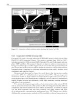
Fig. 65 Microg
raph (a) and schematic (b) of a shear band in a plate of rolled medium carbon steel produced by
ballistic impact showing the transformed zone and the zone of strain localization.
(D.A. Shockey, SRI
International)
Fig. 66 Appearance of adiabatic shear bands in an explosively ruptured Ti-6Al-
4V STA alloy rocket motor. The
material exhibits multiple, often intersecting, shear bands
(open arrows). Slender arrow points to portion of
shear band shown in more detail in (b). Note that the intense deformation has obliterated the α-β
microstructure within the band. The 1.9-mm (0.075-in.) sheet thickness direction is left to right.
(V. Kerlins,
McDonnell Douglas Astronautics Company
Fig. 67 Low-magnification (a) and higher-magnification (b) views of a failure surface produced in vacuum-
arc
remelted AISI 4340 steel (40 HRC) by dynamically shearing in a split Hopkinson torsion bar at a nominal shear
strain rate of 6000 s
-1
. The knobbly fracture surface suggests that local melting occurred. (J.H. Giovanola, SRI
International)
These shear bands are believed to occur along slip planes (Ref 201, 202), and it has been estimated that under certain
conditions, such as from the explosive-driven projectile impact of a steel target, the local strain rate within the adiabatic
shear bands in the steel can reach 9 × 10
5
s
-1
and the total strain in the band can be as high as 532% (Ref 204). An
estimated 3 × 10
6
-s
-1
strain rate has been reported for shear bands in a 2014-T6 aluminum alloy block impacted by a gun-
fired (up to 900 m/s, or 2950 ft/s) steel projectile (Ref 205).
The extremely high strain rates within the adiabatic shear bands result in a rapid increase in temperature as a large portion
of the energy of deformation is converted to heat. It has been estimated that the temperature can go high enough to melt
the material within the bands (Ref 205, 206). The heated material also cools very rapidly by being quenched by the large
mass of the cool, surrounding matrix material; therefore, in quench-and-temper hardenable steels, the material within the
bands can contain transformed untempered martensite. This transformed zone is shown schematically in Fig. 65(b).
The hardness in the transformed bands is sometimes higher than can be obtained by conventional heat treating of the
steel. This increase in hardness has been attributed to the additive effects of lattice hardening due to supersaturation by
carbon on quenching and the extremely fine grain size within the band (Ref 203). However, for an AISI 1060 carbon
steel, the hardness of the untempered martensite bands was no higher than that which could be obtained by conventional
heat treating (Ref 206). In both cases, the hardness of the adiabatic shear bands was independent of the initial hardness of
the steel. For a 7039 aluminum alloy, however, the hardness of the shear bands was dependent on the hardness of the base
material. The adiabatic shear bands in an 80-HV material exhibited an average peak hardness of about 100 HV, while
those in a 150-HV material had an average peak hardness of about 215 HV (Ref 208). For the Ti-6Al-4V STA alloy
shown in Fig. 66, there was no significant difference in hardness between the shear bands and the matrix. In materials that
do not exhibit a phase transformation, or if the temperature generated during deformation is not high enough for the
transformation to occur, the final hardness of the adiabatic shear band is the net result of the competing effects of the
increase in hardness due to the large deformation and the softening due to the increase in temperature.
The width of the adiabatic shear bands depends on the hardness (strength) of the material (ref 206, 208). Generally, the
harder the material, the narrower the shear bands. In a 7039 aluminum alloy aged to a hardness of 80 HV, the average
band width resulting from projectile impact was 90 μm, while in a 150-HV material, the band width was only 20 μm (Ref
208). The average width of the shear bands observed in a Ti-6Al-4V STA alloy (average hardness, 375 HV
1kg
was 3 to 6
μm.
When an adiabatic shear band cracks or separates during deformation, the fractured surfaces often exhibit a distinct
topography referred to as knobbly structure (Ref 205, 206, 207, 208). The name is derived from the surface appearance,
which resembles a mass of knoblike structures. The knobbly structure, which has been observed in 2014-T6 and 7039-T6
aluminum alloys, as well as in an AISI 4340 steel (Fig. 67) and AISI 1060 carbon steel, is believed to be the result of
melting within the shear bands (Ref 205, 206). Although the cracked surfaces of adiabatic shear bands can exhibit a
unique appearance, adiabatic shear failure is easiest to identify by metallographic, rather than fractographic, examination.
Effect of Temperature. Depending on the material, the test temperature can have a significant effect on the fracture
appearance and in many cases can result in a change in the fracture mode. However, for materials that exhibit a phase
change or are subject to a precipitation reaction at a specific temperature, it is often difficult to separate the effect on the
fracture due to the change in temperature from that due to the solid-state reactions. In general, slip, and thus plastic
deformation, is more difficult at low temperatures, and materials show reduced ductility and an increased tendency for
more brittle behavior than at high temperatures.
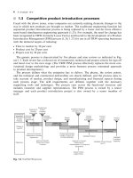
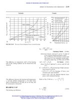
A convenient means of displaying the fracture behavior of a specific material is a fracture map. When sufficient fracture
mode data are available for an alloy, areas of known fracture mode can be outlined on a phase diagram or can be plotted
as a function of such variables as the test temperature and strain rate (Fig. 68). Similar maps can also be constructed for
low-temperature fracture behavior.
Fig. 68 Possible fracture zones mapped for a 0.2% C plain carbon steel in strain rate temperature space. T,
testing temperature; T
m
, melting temperature. The zones, which are shaded in the diagram, are as follows: A,
subsolidus intergranular fracture due to segregation of sulfur and phosphorus; B, high strain rate intergranular
fracture associated with MnS; C, ductile intergranular fracture
may or may not be preceded by B or D; D, low
strain rate intergranular fracture; E, two-phase mixture with fracture at second-
phase particles in the weaker
preferentially strained ferrite. Source: Ref 209
Effect of Low Temperature. Similar to the effect of the state of stress, low temperatures affect the bcc metals far
more than the fcc or hcp metal systems (see the section "Effect of the State of Stress" in this article). Although lower
temperatures can result in a decrease in the size and depth of dimples in fcc and hcp metals, bcc metals often exhibit a
change in the fracture mode, which generally occurs as a change from dimple rupture or intergranular fracture to
cleavage. For example, a fully pearlitic AISI 1080 carbon steel tested at 125 °C (255 °F) showed a fracture that consisted
entirely of dimple rupture; at room temperature, only 30% of the fracture was dimple rupture, with 70% exhibiting
cleavage. At -125 °C (-195 °F), the amount of cleavage fracture increased to 99% (Ref 210). This transition in fracture
mode is illustrated in Fig. 69.
Fig. 69 Effect of test te
mperature on a fully pearlitic AISI 1080 carbon steel. Smooth cylindrical specimens
tensile tested at a strain rate of 3.3 × 10
-4
s
-1
. Specimens tested at 125 °C (225 °F) show fractures consisting
entirely of dimple rupture (a), while at -125 °C (-195 °F),
the fractures exhibit 99% cleavage (b). The size of
the cleavage approximates the prior-austenite grain size. Source: Ref 210
Charpy impact testing of an AISI 1042 carbon steel whose microstructure consisted of slightly tempered martensite (660
HV) as well as one containing a tempered martensite (335 HV) microstructure at 100 °C (212 °F) and at -196 °C (-320
°F) produced results essentially identical to those observed for the AISI 1080 steel. In both conditions, the fracture mode
changed from dimple rupture at 100 °C (212 °F) to cleavage at -196 °C (-320 °F), as shown in Fig. 70. Similar changes in
the fracture mode, including a change to quasi-cleavage, can be observed for other quench-and-temper and precipitation-
hardenable steels.
Fig. 70
Effect of test temperature on an AISI 1042 carbon steel with a slightly tempered martensitic (660 HV)
microstructure that was Charpy impact tested at -196 and 100 °C (-320 and 212 °F). The fracture at -196 °C (-
320 °F) consists entirely of cleavage (a), and at 100 °C (212 °F), it is dimple rupture (b).
A unique effect of temperature was observed in a 0.39C-2.05Si-0.005P-0.005S low-carbon steel that was tempered 1 h at
550 °C (1020 °F) to a hardness of 30 HRC and Charpy impact tested at room temperature and at -85 °C (-120 °F) (Fig.
71). In this case, the fracture exhibited intergranular decohesion at room temperature and changed to a combination of
intergranular decohesion and cleavage at -85 °C (-120 °F). This behavior was attributed to the intrinsic reduction in
matrix toughness by the silicon in the alloy, because when nickel is substituted for the silicon the matrix toughness is
increased and no cleavage is observed (Ref 211).
Fig. 71 Effect of test temperature on a 0.39C-2.05Si-0.005P-
0.005S steel that was heat treated to a hardness
of 30 HRC and Charpy impact tested at room temperature at -85 °C (-
120 °F). The fracture at room
temperature occurs by intergranular fracture (a) and by a combination of intergranular fracture and
cleavage
(b) at -85 °C (-120 °F). Source: Ref 211
The temperature at which a sudden decrease in the Charpy impact energy occurs is known as the ductile-to-brittle
transition temperature for that specific alloy and strength level. Charpy impact is a severe test because the stress
concentration effect of the notch, the triaxial state of stress adjacent to the notch, and the high strain rate due to the impact
loading combine to add to the reduction in ductility resulting from the decrease in the testing temperature. Although
temperature has a strong effect on the fracture process, a Charpy impact test actually measures the response of a material
to the combined effect of temperature and strain rate.
The effects of high temperature on fracture are more complex because solid-state reactions, such as phase changes
and precipitation, are more likely to occur, and these changes affect bcc as well as fcc and hcp alloys. As shown in Fig.
72, the size of the dimples generally increases with temperature (Ref 209, 212, 213). The dimples on transgranular
fractures and those on intergranular facets in a 0.3C-1Cr-1.25Mo-0.25V-0.7Mn-0.04P steel that was heat treated to an
ultimate strength of 880 MPa (128 ksi) show an increase in size when tested at temperatures ranging from room
temperature to 600 °C (1110 °F) (Ref 213).
Fig. 72 Effect of temperature on dimple size in a 0.3C-1Cr-1.25Mo-0.25V-0.7Mn-
0.04P steel that was heat
treated to an ultimate strength level of 880 MPa (128 ksi). (a) and (b) Dimples on transgranular facets. (c) and
(d) Dimples on intergranular facets. Note that dimple size increased with temperature. Source: Ref 213
Figure 73 shows the effect of temperature on the fracture mode of an ultralow-carbon steel. The steel, which normally
fractures by dimple rupture at room temperature, fractured by intergranular decohesion when tensile tested at a strain rate
of 2.3 × 10
-2
s
-1
at 950 °C (1740 °F). The change in fracture mode was due to the precipitation of critical submicron-size
MnS precipitates at the grain boundaries. This embrittlement can be eliminated by aging at 1200 °C (2190 °F), which
coarsens the MnS precipitates (Ref 209).
Fig. 73 Effect of temperature on the fracture of an ultralow-carbon steel. The 0.05C-0.82Mn-
0.28Si steel
containing 180 ppm S was annealed for 5 min at 1425 °C (2620 °F)
, cooled to 950 °C (1740 °F), and held for 3
min before tensile testing at a strain rate of 2.3 × 10
-4
s
-1
. The fracture, which occurs by dimple rupture when
tested at room temperature, exhibits intergranular decohesion at 950 °C (1740 °F). Source: Ref 209
A similar effect was observed for Inconel X-750 nickel-base alloy that was heat treated by a standard double-aging
process and tested at a nominal strain rate of 3 × 10
-5
s
-1
at room temperature and at 816 °C (1500 °F). The fracture path
was intergranular at room temperature and at 816 °C (1500 °F), except that the room-temperature fracture exhibited
dimples on the intergranular facets and those resulting from fracture at 816 °C (1500 °F) did not (Fig. 74). The fracture at
room temperature exhibited intergranular dimple rupture because the material adjacent to the grain boundaries is weaker
due to the depletion of coarse γ' precipitates. The absence of dimples at 816 °C (1500 °F) was the result of intense
dislocation activity along the grain boundaries, producing decohesion at M
23
C
6
carbide/matrix interfaces within the
boundaries (Ref 214).
Fig. 74 Effect of temperature on double-aged Inconel X-750 that was tested at a nominal strain rate of 3 × 10
-
5
s
-1
. (a) and (b) The fracture at room temperature occurs by intergranular dimple rupture. Note the evidence of
dimple rupture network on the intergranular walls. (c)
and (d) At 816 °C (1500 °F), the fracture shows
intergranular decohesion with no dimple rupture. However, the intergranular facets are roughened by the
presence of M
23
C
6
carbides. Source: Ref 214.
A distinct change in fracture appearance was also noted during elevated-temperature tensile testing of Haynes 556, which
had the following composition:
Element Composition, %
Iron 28.2
Chromium 21.5
Nickel 22.2
Cobalt 19.0
Tungsten 2.9
Molybdenum
2.9
Tantalum 0.8
Manganese 1.4
Silicon 0.5
Copper 0.1
Nitrogen 0.1
Three specimens were tested at a strain rate of approximately 1 s
-1
at increasing temperatures. At 1015 °C (1860 °F),
specimen 1 underwent a 72% reduction of area and fractured by dimple rupture (Fig. 75a). At 1253 °C (2287 °F),
specimen 2 exhibited an 8% reduction of area. Fracture occurred intergranularly by grain-boundary decohesion (Fig.
75b). Specimen 3, which was tested at 1333 °C (2431 °F), fractured because of local eutectic melting of TaC + austenite,
with 0% reduction of area (Fig. 75c).