Surface Engineering of Metals - Principles, Equipment and Technologies Part 7 pdf
Bạn đang xem bản rút gọn của tài liệu. Xem và tải ngay bản đầy đủ của tài liệu tại đây (200.32 KB, 20 trang )
Fig. 3.36 Microhardness profile in superficial layer: a) 1045 grade steel, laser
beam hardened with overlapping of hardened zones; b) gray pearlitic cast iron;
1 - after remelt laser hardening; 2 - after transformation laser hardening and
tempering at 450ϒC for 1 h. Fig. b - from Straus, J., and Burakowski, T. [51]. With
permission.)
– surface layer of non-metallic phases composed mainly of metal oxides
and compounds formed as the result of chemical interaction of the atmo-
sphere and thermal reaction of the laser beam with the steel, with gases
dissolved in it and with components of the absorption coating; its layer
usually does not exceed several micrometers;
– remelted and hardened from the melt surface layer, dendritic, with a
martensitic structure; carbides present in the steel underwent total or par-
tial melting; within the area adhering to the intermetallic phase layer, the
melted zone has a diminished carbon content;
– hardened from the solid phase subsurface layer with a non-uniform struc-
ture: martensitic with retained austenite and carbides in the vicinity of the
remelted zone and martensitic with elements of initial structure near the
core. These elements are ferrite in hypoeutectoid steels and cementite in hyper-
eutectoid steels. Throughout the layer, a dispersion of martensite occurs, 1.5 to
2.0 times greater than after conventional hardening;
© 1999 by CRC Press LLC
– tempered core zone, also called intermediate, with a structure of tempered
martensite or sorbite.
Remelt hardening by laser beam causes similar effects as experienced
in electron beam hardening: deterioration of surface roughness (the sur-
face after remelting has the appearance of a weld or overlay) and an
enhancement of service properties such as: tribological, fatigue and anti-
corrosion.
The microhardness profile along the laser beam path is approximately
uniform, with clearly lowered hardness due to the tempering effect of
beam overlap (Fig. 3.36a).
In the remelted zone of martensitic stainless steels and tool steels, re-
sidual tensile stresses prevail after resolidification [233].
By remelting the surface layer of the material it is possible to obtain a
fine-grained structure and partial or total dissolution of precipitation phases
and contaminations in the form of carbides, graphite or oxides which are
usually present in the microstructure. Rapid crystallization (with cooling
rates reaching 10
5
K/s) causes that after dissolution they do not precipi-
tate again or precipitate in a different form. Strongly oversaturated solu-
tions are obtained. For this reason, pure surface remelting is usually ac-
companied by a strong refinement of dispersive phases, e.g., ledeburite, as
well as cleaning of grain boundaries. The latter effect is of particular sig-
nificance to corrosion resistance [50].
Remelt hardening has found application primarily in the treatment of
gray cast irons [50, 150−154], as well as stainless and tool steels [151−161].
Laser remelting of gray cast iron causes total dissolution of graphite and
the occurrence of hard spots in the surface layer. A layer of fine-grained and
non-etching quasi-ledeburite is formed on the surface. It is composed of very
fine carbide precipitations, austenite and martensite, as opposed to ledeburite
in gray cast irons which is composed of pearlite and carbide precipitations.
Under the hardened layer there is an intermediate zone with only partially
dissolved graphite flakes and a hardened layer [60, 153].
As the result of remelting of the surface of gray cast iron, a lower
hardness is obtained in the zone hardened from the melt than in that
hardened from the solid phase (see Fig. 3.36b, curve 1). After tempering at
approximately 400 ϒC, an increase of hardness is obtained in the zone hard-
ened from the melt (Fig. 3.36b, curve 2) [50].
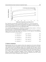
The depth of remelt hardening may reach several millimeters. Surface
hardness of cast iron may even reach 1200 HV0.1. In the hardened condition
the cast iron is resistant to wear (Fig. 3.37) [152] and to corrosion [151]. In
the hardened layers compressive stresses usually prevail [154, 155].
Remelt hardening of gray cast iron has been broadly utilized in the
automotive industry to harden slip rings and engine cylinders, compo-
nents of turbines, cams and gears, obtaining a severalfold extension of
service life [50, 150, 154].
Remelt hardening offers clear advantages in the case of chromium-
bearing medium carbon steels [156], tool steels [157], including high speed
© 1999 by CRC Press LLC
Fig. 3.38 Hardness distributions in superficial layer on low carbon structural steel:
1 and 2 - carburized; 1’ and 2’ - carburized and laser remelt hardened. (From Straus,
J., and Burakowski, T. [51]. With permission.)
Interesting results have been obtained from remelting hardening of
low carbon structural steel (0.14% C; 1% Cr; 4% Ni) after carburizing to a
depth of 1 mm (Fig. 3.38): a 25% increase in hardness and a doubling of
layer depth [60]. Laser remelting has also been applied to titanium after
prior glow discharge nitriding [172].
Laser remelt hardening tests have also been conducted on carbon and
low alloy steels, containing up to 0.2% C, carburized to a level of
0.7 to 0.9% C and coated with a TiN layer, thereby obtaining good adhesion
and a 0.5 mm layer hardened to 880 to 900 HV1 [173].
After remelt hardening, carbon steel grades 1020 and 1045 exhibit a
lowering of the fatigue limit, quite opposite to the effect after remelt-free
hardening.
Remelting of pure nickel [174] and aluminum alloys containing silicon,
titanium, manganese, nickel and iron [175] has also been researched, yield-
ing an improvement of abrasive wear resistance.
Remelt hardening causes insignificant deterioration of surface rough-
ness. Where roughness with Ra<10 to 15 µm is required, laser treatment
should be carried out prior to grinding [5, 11, 29, 51].
Glazing. Laser glazing processes (vitrification, amorphization) are among
the least researched. Glazing, i.e. obtaining of amorphous layers, requires
cooling rates which are greater by an order of magnitude than those typi-
cally obtained by continuous CO
2
lasers. For that reason, Nd-YAG or excimer
pulse lasers are often used, hence the obtained amorphous layers are very
thin (typically: 20 to 40 µm) and the surface relief is not uniform. The applica-
tion of special cooling methods makes utilization of continuous CO
2
lasers
© 1999 by CRC Press LLC
Fig. 3.39 Schematic representation of continuous operation laser glazing: 1 - laser
beam; 2 - introduction of protective gas; 3 - glazed material; 4 - rotating and sliding
stage (ensuring required covering by laser paths). (From Grigoryantz, A.G., and Safonov
A.N. [29]. With permission.)
possible (Fig. 3.39) which, in turn, allows better surface and a greater depth
of the vitrified metal layer. The power densities employed here are 10
6
W/cm
2
and treatment rates of 1 m/s and higher [29].
By ensuring very high cooling rates, the viscosity of the molten metal
may be caused to rise sufficiently high to prevent the formation of crystal-
lization nuclei. The alloy does not crystallize but solidifies in a disordered
form, thus becoming amorphous with properties of a glassy mass.
Not all alloys exhibit a tendency to amorphization [176]. Those that do
must have a certain chemical composition and exhibit an amorphization
rate, related to that composition. For example, for the PdSiCu alloy this
rate is approximately 100 K/s, while for pure germanium or nickel, it is
approximately 10
10
K/s. The amorphization rate is determined by a correla-
tion between viscosity and temperature, the situation of the crystallization
range, the rate of crystal nucleus growth and other factors [29].
The obtaining of the amorphous or fine-crystalline state is possible in
the following cases [29]:
1) Alloys with compositions close to eutectic with a deep eutectic, com-
posed of:
– metal - non-metal. These are formed by metals of the group I of the
periodic table (Ag, Au) and group VII (Fe, Ni, Co, Pd, Pt, Rh) with non-
metals such as Si, Ge, P and C, the content of which in the eutectic is
usually 20 to 25%. Such alloys become amorphous with the application of
relatively small cooling rates: 10
5
to 10
7
K/s;
– metal - rare earth metal. These are formed by metals with normal
valences (Ag, Au, Cu, Al, In, Sn) with rare earth metals (La, Ce, Nd, Y, Gd),
the content of which reaches 20%; the amorphous state is formed easily;
– metals - refractory metals, e.g., Fe, Cu, Co, Ni with Ti, Zr, Nb, Ta.
Amorphization takes place when cooling rates exceed 10
7
K/s.
© 1999 by CRC Press LLC
2) Hypereutectic alloys:
– on a base of tellurium with Ag, Ga, Cu, In; they do not form a low-
melting eutectic and are characterized by non-metallic bonds;
– on a base of lead and tin: Pb-Sn, Pb-Si, Pb-Ag, Pb-Au, Sn-Cu; the eutectic
is situated near the low-melting component; amorphization is possible only
when the cooling rate is greater than 10
8
K/s.
Amorphous alloys exhibit high strength and hardness. As an example,
FeBSi alloys, prior to amorphization, have a hardness of 3500 to 5800 MPa
and 7100 to 11700 MPa after amorphization, while retaining significant ductil-
ity. Although brittle under tensile loading, they allow substantial deformation
- up to 50% - under compressive and bending stresses. At low temperatures,
their strength drops substantially and the alloys exhibit a very good resistance
to corrosion. Some alloys also exhibit special magnetic properties. Amorphous
alloys without phosphorus exhibit high resistance to radiation. In some laser-
amorphized alloys a crack network appears.
To date, many different alloys have been successfully vitrified by a
pulse laser. Among these are FeCSn [177], CuZr, NiNb, FeBSi (Fe
80
B
16
Si
4
,
Fe
77
B
19
Si
4
), FePSi (Fe
83
P
13
Si
4
, Fe
79
P
17
Si
4
), Fe
72
B
14
C
10
Si
4
, Fe
73
P
12
C
11
Si
4
[29], FeB (e.g.,
in triple laser-glazed Fe
83
B
17
alloy, a tri-zone structure was obtained: homog-
enous crystallites, heterogeneous crystallites and metal glass at the surface
[178]), Pd
77
Si
17
Cu
6
, Fe
74.5
Cr
4.5
P
7.8
C
11
Si
2.1
, Fe
81
B
13.5
Si
3.5
C
2
[50].
There are also known methods of reglazing, consisting of laser remelt-
ing of e.g., strip ready-made from metallic glass [50].
A big future is predicted for alloying of steel and cast iron with ele-
ments which enhance their tendency to amorphize (e.g., with boron or sili-
con). The process may be carried out in two stages. The first pass of the laser
beam is for alloying and the second pass (with different parameters) for glaz-
ing [29].
Laser glazing is seldom applied but a significant development is fore-
seen in this area, mainly for raising resistance to tribological wear, includ-
ing primarily magnetic elements, as well as components of assemblies and
instruments working in conditions of severe corrosion hazard.
Densifying (healing). Densifying consists of remelting of the surface
layer or a deposited coating (or coating and superficial layer - Fig. 3.40)
to a certain depth in order to obtain a material of greater density which
usually is associated with a decrease of porosity, but also involves the
liquidation of surface defects in the form of scratches, delaminations, cracks
and open pores [179]. This is accompanied by homogenization of micro-
structure which is important in the case of material prior subjected to
plastic deformation. It is also accompanied by a change of residual stresses
and, in the case of coatings, obtaining of a better metallic bond between
coating and substrate than by spraying alone [180]. In densification pro-
cesses, relatively low power densities and low treatment rates are applied.
This allows gases present in the melted material to escape to the surface
of the laser-melted pool. A usable effect of densification is an increase of
hardness and improvement of surface smoothness, an enhancement of
© 1999 by CRC Press LLC
Fig. 3.41 Effect of laser remelting on properties of plasma sprayed coatings from mix-
ture of 80% powdered GSR-3 material (composition: Ni, Cr, B, Si) and 20% powdered
TiC: a) hardness distribution; b) abrasive wear resistance; 1 - plasma sprayed coating;
2 - plasma sprayed and laser remelted coating; 3 - detonation sprayed coating.
and WC-Ni [188]. For a significant improvement of corrosion resistance it is
sufficient to remelt the thermally sprayed coating to a depth equal to 20 to 50% of
its thickness [50].
– Electrodeposited coatings (primarily to remove scratches and cracks) [11].
Smoothing. Laser smoothing of surfaces is carried out with the use of
the same range of process parameters as remelt hardening. In the micro-
structure of the material subjected to smoothing, the same phase and
structural transformations take place as in remelt hardening. These trans-
formations are not, however, the main technological aim of the process, but
rather the reduction of surface roughness and a change in the profile of
surface unevenness. They occur under the influence of hydrodynamic mix-
ing of the molten material, due to thermocapillary forces which bring about
convection. In the pool of the molten material, a high temperature gradient is
formed, along with related gradients of surface tension. This causes a rapid
circulation of the liquid, but only limited to a zone thinner than the entire
melted layer (Fig. 3.42). For example, the rate of circulation in molten iron
may even reach 150 mm/s [29]. Pressure changes within the molten pool are
compensated by a change of shape of the pool surface.
The strongest effect on smoothing is that exhibited by power density. Within
the range 5°10
3
to 5°10
4
W/cm
2
it is possible to obtain a surface which is
smoother than after machining [29]. The recommended practice calls for low
power densities and big diameters of the laser spot, in order to remelt the
surface layer only to a shallow depth. This is because in such conditions
convection whirlpools are broken down into a series of smaller vortexes,
conducive to a smoother surface. Relatively low treatment rates also lead to
the obtaining of a more favorable surface profile: lower asperities and greater
asperity peak radius.
© 1999 by CRC Press LLC
introducing an alloying additive into the surface layer of the material is by
remelting with hydrodynamic mixing before solidification.
Laser Surface Alloying (LSA) consists of simultaneous melting and mixing
of the alloying and the alloyed (substrate) material. The action and pressure
of the laser beam cause both materials to melt; a pool of molten material is
formed in which intensive mixing, due to convection and gravitational move-
ments, forms a flash at the pool surface (Fig. 3.42). At the interface between
solid (substrate) and liquid (alloy), a very thin diffusion zone appears, usu-
ally not exceeding 10 µm. Only in some rare applications do the alloying
components diffuse to depths of 200 to 300 µm. This takes place by diffusion
by narrow canals of the molten phase along solid grain boundaries and
grain blocks or, in the case of displacement of atoms by dislocations, due to
local deformations.
When the action of the laser beam ceases, the alloy thus formed solidi-
fies while the substrate material in its direct vicinity becomes self-hard-
ened. Structure, chemical composition, and physical as well as chemical prop-
erties of the alloy are different than those of the substrate or of the alloying
material. First of all, the layer of the alloy does not, in principle, exhibit the
characteristic layer structure, typical of diffusion processes. Due to convec-
tion mixing of the alloy, there are no transitions from phases with a higher
concentration of the alloying element to phases with lower concentration. All
phases in the remelted layer are uniformly distributed along its entire depth.
An exception to this is the earlier mentioned very thin diffusion zone at the
interface between solid and liquid. The alloy layer is bound metallurgically
with the substrate.
The alloy layer, rich in alloying components, usually exhibits a higher
hardness than that of the substrate, a higher fatigue strength, better tribo-
logical and corrosion properties, but at the same time with poorer smooth-
ness of the surface in comparison with the condition prior to alloying.
These properties depend to a very high degree on the uniformity of mix-
ing of the alloy in the molten phase, which, in turn, depends on the inten-
sity of convection exchange of mass in that zone [193].
Depending on the method of introducing the alloying additive to the
molten pool, we distinguish remelting and fusion (Fig. 3.43).
Remelting. Remelting is a two-stage process, consisting of prior depo-
sition of the alloying material on the substrate and subsequent remelting it
together with the surface layer of the substrate material (Fig. 3.43a). Usu-
ally, the thickness of the remelted surface layer is comparable with the thick-
ness of the deposited alloying material, i.e., the mixing coefficient k
p
is ap-
proximately 0.5. The process of remelting begins from the alloying coating
and propagates by convection and conductivity into the surface layer of the
substrate. The alloying material dissolves completely in the substrate ma-
terial.
Alloying is accomplished with the employment of power densities in
the range of 5°10
4
to 10
6
W/cm
2
, which are greater than those used in harden-
ing, and exposure times from tenth to thousandth parts of a second
© 1999 by CRC Press LLC
[29, 192]. The greater the power density, the bigger the depth of remelting.
High power densities may lead to the formation of plasma and vaporiza-
tion of material (Fig. 3.44).
In principle, remelting is always accompanied by the occurrence of plasma
and vaporization of material On the one hand plasma screens the surface
from further laser heating; on the other, however, it interacts with the sur-
face of the melted metal pool exerting pressure and causing the displace-
ment of components of the molten material. In the pool, precisely at the site
of penetration of the laser beam into the material, a conical pit is formed.
The surface of this funnel is acted upon by the hydrostatic pressure of the
liquid from below and by vapour pressure from above. Between the two, an
unstable equilibrium is formed, constantly disturbed by, among other fac-
tors, relative movement of the beam and the treated object. The pit moves
toward as yet unmelted material (in a direction opposite to that of the object
relative to the beam). Behind the displaced pit, vapour pressure causes a
filling in of the discontinuity. In consequence, on the molten surface there
appears a characteristic waviness, similar to that which is typical of a weld
seam.
Because of the above-described two-directional interaction of plasma on
the molten pool, different methods of slowing down this action on the molten
material are used. Among these are blowing away of the plasma cloud by a
neutral gas, heated in order not to impair the energy effect. There are also
methods of enhancing the action of plasma, e.g., by blowing away the plasma
cloud but with the simultaneous recycling of the reflected laser radiation
back to the treatment zone by a set of plane mirrors or a mirror dome. Natu-
rally, the flow of protective gas always protects the optics of the laser head
against the deposition of gases, vapors and solid particles, created during
treatment.
Alloying is accomplished with the application of one or several passes
of the laser beam. The alloying material is deposited on the substrate by
[40, 41, 48, 53, 54]: painting, spraying of suspensions, covering by adhe-
sive powders or pastes (containing P/M ferrous alloys of alloying metals,
boron carbides, tungsten and titanium carbides and borax), thermal spray-
ing (flame, arc, plasma and detonation), vapour deposition, electrodeposi-
tion, thin foil, plates, rods or wires, or by E.D.M. The thickness of the
deposited coating ranges from several to more than 100 µm.
In the case of P/M materials, the efficiency of laser heating is greater
than for solid materials, on account of the higher coefficient of absorption
of laser radiation through powder, usually approximately 0.6. A relatively
significant role is played by substrate surface roughness. Its growth causes
an improvement of adherence of the powder mass to the substrate and thus
an improvement in the passage of alloying components into the molten pool,
attributed to rapid melting of asperities.
Alloying components can also be introduced to the substrate from the
melt (Fig. 3.45). The alloyed part is placed in a liquid; the laser beam
reaches the surface through a vapour/gas channel formed in the liquid
© 1999 by CRC Press LLC
surface covered by them) or in varnishes, e.g., bakelite together with activa-
tion additives, such as ammonium chloride or borax, or in liquid hydrocar-
bons or liquids containing carbon, e.g., hexane, acetone, toluol, carbon tetra-
chloride, mineral oil, etc. Carburization is applied in order to raise the hard-
ness of plain carbon steels (4500 to 14000 MPa);
– laser nitriding: in pastes containing ammonium salts, urea (NH
2
)
2
CO,
in gaseous or liquid nitrogen. Nitriding is applied to steels, as well as tita-
nium, zirconium, hafnium or alloys of these metals, in order to increase
hardness, resistance to tribological wear and to elevated temperatures;
– laser siliconizing: in pastes containing silicon powder or in liquids (e.g.,
in a suspension of silica gel H
2
SiO
3
) in order to enhance thermal, corrosion
and tribological resistance of steel;
– laser boriding: in pastes constituting mixtures of boron powders, an-
hydrous boric acid B
2
O
3
, boron carbide B
4
C, borax Na
2
B
4
O
7
·10H
2
O, ferro-
boron with filler material, e.g., glue. This process is carried out in order to
increase hardness and abrasive wear resistance of metals.
2) Metals: Co, Cr, Sn, Mn, Nb, Ni, Mo, W, Ta, V or their alloys, e.g., Cr-Mo-W,
Ni-Nb. An unfavorable property of remelt alloying with metals is the formation
of supersaturated solid solutions, significantly exceeding solubility in equilib-
rium conditions. The formation of intermetallic compounds is also possible.
The utilization of metals and their alloys leads to changing of mechanical
properties of ferrous, aluminum, titanium and copper alloys.
3) Different compounds, mainly carbides of refractory metals: TiC,
NbC, VC, TaC, WC, Nb
2
C, Ta
2
C or alloys of carbides of these metals, de-
posited by thermal spraying and by electrodischarge, as well as in the
form of pastes (powder + liquid glass, powder + silicate glue, etc.).
Alloying is applied to metals and alloys, mainly to steels and cast irons
(Fig. 3.46 and 3.47) by single elements raising heat resistance, corrosion
resistance and abrasion or erosion wear resistance. Among these are Mo, W,
C, Cr, B, Mn, Ni, Co, Zn, Cd, Si, Al and composites of elements, e.g. B-C, B-Si,
Co-W, Cr-Ti, Fe-Cr, C-Cr-Mn, Al-Cr-C-W and alloys, e.g., Cr
2
C
3
, Cr
3
C
2
-NiCr
2
,
WC-Co, oxides Cr
2
O
3
, TiO
2
, B
2
O
3
[29, 192, 195, 201], all allowing the obtaining
of a better set of properties than by alloying with only single elements.
Alloying is most often applied to different types of steels [194-196]:
– Structural carbon, e.g., 1045 [197-200] and low alloy grades with car-
bon, chromium, molybdenum [198-200], P/M carbides, e.g., WC, TiC or mix-
tures of WC-Co [197], chromium pastes [201], boron, deposited electrolyti-
cally or in the form of paste. As an example, the microhardness of carbon
(0.2% C) steel is increased by alloying from 2.5 GPa to 8.5 GPa, with a layer
thickness of 0.4 mm [202].
– Tool steels: with boron [202], boron carbide or its composites with
chromium (e.g., 75% B
4
C + 25% Cr [208]), by different composites of carbides
[209], by tungsten, tungsten carbide and titanium carbide [210], by chromium
or vanadium boride [211], by vanadium carbide [212] or by Mo-Cr-B-Si-Ni
composites [213].
© 1999 by CRC Press LLC
Remelt alloying is often applied to cast irons [214], particularly gray
[215-217] and high strength [218]. These are alloyed with the use of Fe-Si
powder packs [215], carbon (up to a content of 22% C) in order to enhance
resistance to erosion wear[216], with boron [218], silicon, nickel and its al-
loys [217] and with chromium [214].
Good results have been obtained by remelt alloying of aluminum alloys
[219], including Al-Si alloys [220, 221]. For example, the Al25
*
grade, alloyed
with the application of pastes based on powders of NiCr, FeCuB, or NiCrMo,
exhibits a significant increase in hardness and resistance to abrasive wear
[219], in a way similar to the D16
*
grade, alloyed by carbides, e.g., B
4
C, Cr
3
C
2
,
B
4
C+Cr, B
4
C+Cr
3
C
2
, or by a composite B
4
C+Cr
2
O
3
+CaF
2
[224]. Powder pack
alloying of Al-Si alloys by nickel, chromium, iron, silicon and carbon clearly
raises their heat resistance [221]. Similarly, alloying by Fe, Fe+B, Fe+Cu,
Fe+Cu+B powders, predeposited by painting, in a mixture with zapon var-
nish significantly raises hardness, although the distribution of alloys in the
remelted zone is not homogenous [220].
Alloying of titanium by remelting of electroplated chromium, manga-
nese, iron or nickel coatings causes a rise in hardness of the surface layer
from below 1500 MPa for the titanium substrate to 5500 to 10000 MPa for the
alloyed layer [222]. The hardness of a laser hardened WT3-1
*
titanium alloy
rises, relative to the initial hardness value by a factor of 1.1 to 1.6. This may
be further enhanced by alloying with powders of Al
2
O
3
, FeCr, a-BN and oth-
ers [223] or by borides and carbides of transition metals (Mo
2
C, Mo
2
B
5
, WC,
W
2
B
5
, VB
2
, B
4
C, B
4
C +CaF
2
) together with chromium [224].
Research is currently being conducted to study the strengthening of
low-carbon overlays by alloying, e.g., by chromium, predeposited by electro-
plating [225].
Fusion. Fusion is a single stage process. It involves creating a pool of
molten substrate material with the laser beam and the introduction into this
pool of the alloying material in the form of solid particles (powder or paste)
completely or partially soluble in the substrate, or in the gaseous form (see
Fig. 3.43b). Fusion is accomplished only with the aid of continuous operation
lasers because the alloying material may be introduced to the molten zone
only while laser heating is on, and not during lapse between pulses.
The aim of fusion is the same as that of remelting, i.e., the obtaining of a
surface layer in the form of an alloy or a coating with properties which are
better than those of either the alloyed or the alloying material.
In the case of powder fusion alloying, the process of melting of both
materials is simultaneous: solid particles of the alloying material are heated
and may melt already at the moment of entering the site of the laser
beam. Not completely melted, they drop into the pool of the simultaneously
melting alloyed material.
The powder added may be a homogenous material or it may constitute
a mixture of powders of several materials. The powder should be introduced
in a stream of protective atmosphere in order to avoid oxidation (Fig. 3.48a).
However, the gas may cause porosity of the alloyed layer.
© 1999 by CRC Press LLC
Ti + ˚N
2
⌠ TiN – 336 kJ/mole (3.17)
The titanium nitrided (TiN) formed features a hardness of over 2000 HV
[237−239]. If the alloyed grade is TiAl6V4, the titanium nitrided layer ob-
tained has a thickness of 50 to 500 µm [237, 238]; if the alloyed grade is
titanium the thickness may reach 1 mm [239]. Some problems may, in this
case, be caused by oxidation and the formation of TiO
2
oxides [239]. This
method may be used in alloying of plasma sprayed coatings made of tita-
nium and its alloys on steel.
Laser carburizing of low carbon steels by carbon formed from the de-
composition of pure propane or propane mixed with neutral gases, e.g.
argon, neon or helium, has also been studied. The carburized layers thus
obtained exhibit thicknesses up to several millimeters [240]. Carburizing
gases have also been utilized in attempts to form titanium carbide (TiC)
on titanium and its alloys [29, 192].
3.5.2.3 Cladding
Cladding, also known as laser plating or hardfacing, is accomplished with
process parameters similar to those in alloying and consists of melting a
thick layer of the plating material and surface melting of a very thin layer
of the substrate material. In hardfacing, the coefficient of mixing k
p
is
usually 0.1. The aim of hardfacing is not the mixing of the plating mate-
rial with that of the substrate but melting of the deposited coating mate-
rial or its deposition and remelting in order to obtain better resistance to
erosion, corrosion, abrasion and to other service hazards than that of the
substrate material. The coating material may be soluble or insoluble in the
substrate [241−252]. The intermediate layer formed between the substrate and
the plating is usually of a metallurgical character, in which case it causes
strong bonding of the latter to the substrate [11]. In a manner similar to alloy-
ing, the plating material may be deposited onto the substrate by the following
means:
– A two-stage process prior to laser treatment. The remelting process
progresses from the top which favors the formation of defects, such as
blisters and incomplete melting near the substrate. The formation of these
defects is also favored by the binding material (most often: zapon varnish,
epoxy resin, fats, synthetic materials, liquid glass, silicon glue, shoemaker’s
glue, solutions of borax and acetone, isopropyl alcohol, alcohol solutions
of resin, nitrocellulose and indiarubber glue, as well as crazy glue) [27].
Such materials, added to the powders in order to ensure better adhesion
to the substrate, evaporate during laser heating and periodically screen
the melted pool, resulting in non-homogenous remelting of the substrate.
Since this process requires the prior deposition of the plating material
onto the substrate in the form of a layer of powder, foil, thin sheet or thick
coating) it can, for simplicity, be called a coating process. Each form of plat-
© 1999 by CRC Press LLC
ing material requires different processing parameters, mainly input power
density and hardfacing rate. Parameters which are higher than optimum
cause excessively deep remelting of the substrate while lower param-
eters may cause a droplet form of the plated layer. In the case of pow-
dered or paste materials there usually occurs a burnout of the binding
material through the sides of the plating, often causing the necessity of
redeposition of the powder or paste when carrying out two or more plat-
ing operations.
Fig. 3.49 Schematic of cladding: a) two-component, powder; b) wire: 1 - laser beam; 2
- laser path on clad material; 3 - containers with components of cladding powder; 4 -
cladding wire; 5 - source of direct resistance heating current; 6 - substrate. (Fig. a - from
Abbas, G., et al. [244], Fig. b - from Hinse-Stern, A., et al. [252]. With permission.)
– In a single-stage process, during laser treatment (Fig. 3.49), using
the coating material in the form of powder or rod (strip). The powder is
fed by pouring (by inertia or by vibratory mechanism) or is transported
with the aid of a gas, non-neutral (e.g., air) or neutral (e.g., nitrogen, helium
or argon) to the coating material.
Similarly as in fusion, it is possible to utilize active gas for the delivery
of powder because an exothermic reaction with this gas may intensify the
plating process. The rod is fed mechanically in a continuous manner. In
the case of plating from a powder form, the process is termed injection plat-
ing; in the case of remelting of a rod, the term used is overlay plating.
A powder or a powder mixture (Fig. 3.49a) blown into the zone of the
laser beam is melted and in the melted form falls onto the surface of the
substrate. The plating layer therefore forms from the bottom up, as a
result of solidification of the melted material at the surface of the sub-
strate material. This type of hardfacing requires the use of a nozzle, coupled
with the laser head and feeding the powder in a direction with or counter
to the movement of the load. It also requires the use of powders of
appropriate granulation (Fig. 3.50). The most often used powder granula-
tion is 40 to 80 µm, while the rate of powder feed does not exceed 1 g/s.
Powders should be dried before application [11]. Powder plating by laser
is characterized by low energy consumption, in comparison with other
© 1999 by CRC Press LLC
as erosion and corrosion hazards, e.g., plating of sealing surfaces of valve
seats and valves in combustion engines, water, gas and vapor separators, as
well as components of metallurgical tooling.
Joint resistance to wear and corrosion is ensured by layers of Co-Cr-Mo-
Si. The presence in the matrix of hard intermetallic phases of composition
ranging from CoMoSi to Co
3
Mo
2
Si ensures tribological properties, while the
presence of chromium - anti-corrosion properties. Similar resistance is ob-
tained by the application of Cr-Ni-B-Si-Fe plating. There are known examples
of plating austenitic stainless steels [251] in order to increase their sear resis-
tance and of plating heat-resistant materials, like the Nimonic alloy. A typi-
cal laser hardfacing treatment is the plating of austenitic stainless steels with
tungsten or cobalt carbides [11, 250, 251].
Laser hardfacing is used to plate steel with creep-resistant layers that are
resistant to abrasive and erosive wear, especially at elevated temperatures.
Steel may be plated with alloys of cobalt [247], titanium, alloys and/or mix-
tures of: Cr-Ni [251], Cr-B-Ni, Fe-Cr-Mn-C [249], C-Cr-Mn, C-CrW, Mo-Cr-
CrC-Ni-Si [29], Mo-Ni [243], TiC-Al
2
O
3
-Al, TiC- Al
2
O
3
-B
4
C-Al, aluminum,
stellite [241], Hastelloy [251], carbides WC, TiC, B
4
C [246], SiC [244], nitrides,
including BN [245], oxides of chromium and aluminum, etc. Alloys of cobalt
may be plated with alloys of nickel, yielding high temperature erosion-resis-
tant so-called superalloys. Titanium alloys may be plated with boron nitrides
[245], while Al-Si alloys with silicon. Aluminum and copper may be hardfaced
with a mixture composed of 91% ZrO
2
-9% Y
2
O
3
or ZrO
2
-CaO [242]. A mixture
often used for laser rebuilding of worn surfaces is Cr-Ni-B-Fe, infrequently with
the addition of C and Si. It is predicted that practical applications will be found
for laser glazed SiO
2
platings, deposited on creep-resistant alloy substrates, used
for heating elements, working at 900 to 1000ϒC in strongly oxidizing, carburiz-
ing or sulfiding environments, e.g., Incoloy 800H.
Coating composites of hard and refractory materials form mixtures of
powders of these materials with powders of the plated steel or powders of
iron, used as bonding. For example, in the case of the WC+Fe composite
(or WC+Co, WC+NiCr), the rapid plating process, rendering diffusion trans-
formation WC⌠Fe impossible, causes carbides to retain their hardness of
approximately 11000 MPa which is equal to maximum achievable hardness
of tungsten carbides present in the matrix of tool steels containing tungsten
after conventional heat treatment.
Tool steels, especially those for forming tools, are laser plated by stellite
in order to protect against abrasive wear. The creep resistant alloy Nimonic
8A (over 70% Ni, 20% Cr, additives of Al, Co) used for gas turbine blades,
laser-plated with stellite, exhibits an almost 100-fold increase in resis-
tance to abrasive wear. It is noteworthy that laser stellite plating is more
favorable (higher hardness, finer structure) than weld stellite overlaying
(by the TIG and gas methods). The Cr
2
O
3
oxide, laser deposited onto aus-
tenitic steel (e.g., 321 grade), doubles its creep resistance. In the automotive
industry, valve seats and flanges have been laser plated for an appre-
ciable time.
© 1999 by CRC Press LLC
The thickness of hardface layers is greater than that of alloyed layers and
may reach several millimeters. The width of a single plated seam (with the
laser beam scanning the surface with a frequency of 10 to 300 Hz, trans-
versely to the movement of the load) may exceed 10 mm [24]. The productiv-
ity of plating is from several to over 100 mm/s [50]. The quality of plated
layers, in terms of tightness, bonding to substrate and hardness, is better
than that of thermally sprayed (including plasma)coatings [29, 195]. Laser
hardfacing may cause a lowering of the fatigue limit for structural steels,
depending on the type of plating. The more refractory the plating material,
the greater the fatigue limit drop.
In laser hardfacing, the problem of surface roughness appears to be
greater than in other laser alloying. Usually, surface roughness rises with
the melting point of the plating material. For that reason, often mixtures
are used, most often powder mixtures, containing powders with a high
and a low melting point, e.g. TiC+Al
2
O
3
+Al+B
4
C, although this has a nega-
tive effect on the hardness of the plating [50, 51].
3.5.3 Evaporation techniques
Laser beam evaporation techniques are divided into three groups: pure
evaporation, rapid evaporation, combined with detonation hardening, and
ablation cleaning.
3.5.3.1 Pure evaporation
Pure evaporation consists of utilization of only the thermal action of the
laser beam for relatively slow evaporation of the material which later -
due to various physical and chemical phenomena - is deposited by itself
or together with another material, e.g., gas, thereby forming a coating. Meth-
ods involving these phenomena are the so-called CVD (see Part II, Chapter 5)
or PVD (see Part II, Chapter 6).
3.5.3.2 Detonation hardening
This method involves the utilization of the energy of a shock wave and of
the mechanical pulse to mechanically strengthen the material. A certain
analogy exists here to the explosive hardening of materials by a shock
wave which utilizes the energy of the explosive material or an explosive
gas mixture. The latter method has been used for a long time to harden
objects or their selected sites. When the laser beam is used, it is possible to
locally harden metallic materials but only on condition that they are heated
by an ultra-fast pulse method [253].
During the action of a laser radiation pulse on the material, the dura-
tion of which significantly exceeds relaxation times which range from
10
-9
to 10
-11
s, thermal energy is conducted into the material. Its heating,
melting and evaporation occur in accordance with traditional laws of energy
transfer [29].
© 1999 by CRC Press LLC
When, on the other hand, the duration of the pulse is of the order of
10
-8
to 10
-10
s, and power density is 10
10
to 10
12
W/cm
2
and higher, the time
of action of the laser pulse on the material approaches that of the time of
relaxation. For this reason, it is impossible to conduct the energy away into
the core of the material. A very high power density in the microzone of the
surface layer causes the material to transform into the plasma state. The
heated plasma expands, very high pressures are set up, similarly to the
case of an explosion, and a shock wave may be formed. But it is formed
only when the duration of the pulse is shorter than the time of propagation
of the shock wave in the microzone. During this time the pressure in the
surface layer of the material is very high, while in the core of the material it
drops rapidly. Non-homogeneity of propagation of pressure is the cause of
formation of the shock wave [29].
For the majority of solids (of approximately 1 cm thickness) the time of
propagation of shock waves is approximately 10
-5
s. In this case, laser pulses
of even 10
-6
to 10
-7
s may bring about the formation of a shock wave. When the
power density is 10
9
W/cm
2
, the duration of the pulse is 10
-8
s and the coeffi-
cient of absorption of the incident radiation is 0.1, pressure values for CO
2
laser radiation are 0.212·10
5
MPa for copper, 0.121·10
5
MPa for aluminum
and 0.060·10
5
MPa for beryllium. The action of radiation from a ruby laser is
twice as strong [254]. Extreme values may be significantly higher and may
reach values comparable to pressures occurring during the explosion of a
hydrogen bomb [8].
Besides the shock wave formed with a pulse laser of 10
-8
s duration and
10
8
W/cm
2
power density, there is an additional effect on the material of
the mechanical impact, formed as the result of a rapid transition of the
material into the plasma state and its evaporation into the surrounding
space. A strongly ionized plasma cloud causes the screening of the treated
object from the laser beam, especially from medium wave infrared radiation
[11]. The plasma formed expands to the surface of the treated material, a
crater is formed and the plasma runs up its walls to the outside, strengthen-
ing the material by its pressure [6, 14, 44, 53, 54].
The mean evaporation rate
υ
avg
is
(3.18)
where: M - mean particle mass of material; R - gas constant; T
n
- mean
temperature of material after radiation by n laser pulses.
In such a case the material is subjected to the mechanical impact of
unit energy equal to [29]:
E =
ρ
z
0
υ
avg
(3.19)
where:
z
0
- thickness of layer of evaporated material (Fig. 3.51);
ρ
- density of
treated material.
© 1999 by CRC Press LLC
thickness. Since in this technique it is possible to heat the material to tem-
peratures higher than critical, in the sites of former pearlite grains, a marten-
sitic structure of 6900 MPa microhardness is formed. Under the heat affected
zone (HAZ), a thick zone (700 to 750 µm) is found, formed by mechanical
strengthening, occurring practically in the cold condition. This zone con-
tains in its structure a big number of mechanically twinned ferrite grains
(Fig. 3.51c) Due to the twining, the microhardness of ferrite grains grows to
approximately 2300 MPa. Their initial hardness was 1700 MPa. The effect of
mechanically induced plastic deformation decreases with distance from the
crater walls [29]. Both the size of the mechanically affected zone as well as
that of the plastically deformed zone grow with an increase of energy of
radiation (Fig. 3.51d) [254].
The main practical disadvantage of detonation hardening is the for-
mation of the crater and the connected deterioration of quality of the
object surface. In order to limit this disadvantage, a method is used involving
the deposition of thin interlayers in the form of liquid or paste, or even thin
foil causing the crater to form on these interlayers, while the mechanically
affected zone forms in the treated material. Moreover, the interlayer material
is selected such that the impact effect is amplified and, consequently, the
effect of plastic deformation is enhanced.
Among the drawbacks of this technique are, besides the above, small di-
mensions of the mechanically affected zone, relatively small hardness in-
crease and low efficiency [29].
This type of treatment also allows the obtaining of high mechanical
strengthening in the case of soft materials, e.g., aluminum, or of very hard
materials, including some steel grades. Although in practice, impact hard-
ening has been applied to high strength aluminum alloys, it has, neverthe-
less not gone beyond the phase of experimentation [5, 29, 48, 53]. Laser-
generated shock waves may also liquidate microcracks [8].
3.5.3.3 Ablation cleaning
Evaporation or sublimation of the solid under the influence of high power
density laser beam radiation is called laser ablation. This phenomenon,
discovered in the 1970s, has been utilized to clean surfaces. The mechanism
of ablation cleaning is akin to that of detonation hardening, although it
serves to strip coatings from substrates.
At the moment of formation of plasma, under the influence of laser
radiation, the thermal energy of the plasma is, by way of convection and
electron conduction, delivered to the material (both coating and substrate)
which at that time are not reached by the electron beam. This is due to the
fact that the beam is screened off by the plasma or there is an interruption
between pulses. At the same time, due to evaporation and sublimation,
the stream of energy and matter (evaporated particles of coatings) moves
in the opposite direction, i.e., away from the material. The zone in which two
opposite fluxes of energy meet forms the ablation front - a boundary of high
density and plasma temperature gradients. In the zone of material movement
© 1999 by CRC Press LLC
in the direction of the substrate, a shock wave is formed as the reaction of the
system to explosive evaporation of the material from the surface of the coat-
ing.
After passing through a thin coating, the shock wave rebounds from
the surface of the substrate (interface), changes its direction of propaga-
tion and causes detachment (spalling) of the coating material. If, on the
other hand, the coating is thick, the velocity of shock wave propagation is
reduced sufficiently for it to transform into an acoustic (sound) wave,
causing vibrations of the substrate which are also conducive to detach-
ment of coating particles. The cycle is repeated until total stripping of
coating material is effected. Next the shock wave is absorbed by the sub-
strate.
The depth of the ablation front depends on the wavelength of laser radia-
tion and is usually within the range from 0.3 µm (excimer laser) to approxi-
mately 1 µm (Nd-YAG laser). This is also the thickness range of one stripping
of the coating, i.e., after one pass of the laser beam. Passes may be repeated.
For a laser of 2·10
-8
s pulse, momentary pressure is approximately 20 MPa
while the velocity of explosively evaporated particles reaches 0.1 km/s, with
an acceleration of 10
10
m/s. Momentary temperature is low and does not
exceed 300ºC [261].
The ablation technique may be used to strip varnish coatings from
metal objects, e.g., thin conductors of 0.05 to 0.3 mm are stripped of their
insulating coatings [29]. It is also possible to clean works of art (paintings,
sculptures) made of metal, stone, porcelain, glass, wood, cardboard, ivory,
cloth or feathers of even centuries-old contaminations like patina, fats, oils,
oxides, paints, varnishes, fungus, soot and solid particles adhering by other
means [261].
3.5.4 Laser techniques for formation of thin and hard coatings
The laser beam allows the formation of thin and hard coatings of high
hardness or with special properties, similar to or same as those obtained
in typical CVD and PVD processes. It may be applied as an individual
operation or as part of several other treatment cycles. Currently, it is
possible to distinguish four methods of laser formation of thin and hard
coatings: fusion alloying in gas, pure evaporation, pyrolytic and chemi-
cal.
3.5.4.1 Coating formation by the fusion alloying in gas method
By the utilization of fusion alloying in the gas phase, described in Section
3.5.2.2, it is possible to form coatings of greater thickness and better adhesion
to the substrate than by typical CVD and PVD methods.
To this day, a known and practiced method is fusion alloying in gas coatings
made from titanium and its alloys, sprayed onto any metal substrate [255].
In the latter case, after plasma spraying, in a protective atmosphere of
coatings of 100 to 200 µm thickness, made from powder of 10 to 40 µm grain
© 1999 by CRC Press LLC
size, the coatings are subjected to the action of a laser beam of 10
6
W/cm
2
power density, with simultaneous blowing of nitrogen into the pool of mol-
ten titanium at 120 kPa pressure. A weakly ionized plasma, composed of
nitrogen and titanium vapours is obtained. As the result of a synthesis of
titanium from the substrate with atomic nitrogen from the ionized plasma,
the TiN nitride is formed. The thickness of the obtained titanium nitride
coating is approximately 100 µm; it is thus more than 10 times greater than
that obtained by typical CVD and PVD methods. The consumption of nitro-
gen is 1 l/s [255].
3.5.4.2 Formation of coatings by the pure vapour deposition
method
During pure evaporation of the coating material with the aid of a laser
beam, and the deposition of vapours of that material (e.g., Al, Cr) on the
substrate in its pure form or in the form of a compound obtained from the
synthesis of this material (e.g., Ti) with the reactive gas (e.g., N
2
), coatings
are obtained which are exactly the same as those obtained by typical PVD
methods, such as electron beam, resistance or arc evaporation [256]. In the
case of laser evaporation, scattered debris of melted material and its con-
taminants may be expected. For this reason, for each type of evaporated
material, the appropriate type of laser should be selected. Generally, the
rule is that for vapour deposition of metals, better results are obtained
Fig. 3.52 Schematic of equipment used for evaporation PVD technique, using the
laser beam to evaporate a superconductor and to vapour deposit it on a semiconduc-
tor material: 1 - laser beam (Nd-YAG laser, l = 1.064 µm (0.532 µm, 0.359 µm,
0.266 µm), f = 1 to 10 Hz, or excimer laser XeCl (
λ
= 0.308 µm, f = 5 Hz) with energy
density in spot = 7.5 J/cm
2
; 2 - quartz lens; 3 - laser window; 4 - vacuum tight shell;
5 - turbomolecular pump, ensuring 10
-4
Pa in chamber; 6 - rotating target with disk of
laser evaporated YBa
2
Cu
3
O
7
(which at 90 K becomes a superconductor); 7 - plates of
polycrystalline ZrO
2
and monocrystalline SrTiO
3
(which at 85 K becomes a supercon-
ductor), on which vapours of YBa
2
Cu
3
O
7
condense,
rotating relative to target; 8 - plate
holder and heater (maximum temperature 600ϒC); 9 - inlet for oxygen to ensure re-
quired partial pressure. (From Endres, G., et al. [256]. With permission.)
© 1999 by CRC Press LLC
with the application of Nd-YAG lasers (
λ
= 1.06 µm), while for non-metals,
the recommended laser is the CO
2
type (
λ
= 10.6 µm) [29]. Naturally, excep-
tions to this rule do exist.
The laser beam may be utilized to vapour deposit metals (e.g., Al, W, Ti,
Cr), semi-conductors (e.g., ZnS, ZnSe, GaAs) and insulators (e.g., SiO
2
). The
rate of deposition ranges from fractions of a nanometer to hundreds of na-
nometers in 1 s [29].
A significant, 100- to 1000-fold increase in deposition rate may be ob-
tained by additional action of the laser beam on the electrically or electrolyti-
cally deposited coating, due to the increase of the temperature gradient and
the consequent rise in concentration of the deposited ions [29].
Vapour deposition by laser of materials for the needs of electronics
must be carried out in vacuum [257]. Fig. 3.52 shows a laboratory system
for laser evaporation of a superconductor and its deposition on a semi-
conductor substrate [256].
Laser vapour deposition of coating materials is applied less frequently
than electron beam deposition and when it is, it is for the need of electronics
rather than for the machine industry.
3.5.4.3 Pyrolytic and photochemical formation of coatings
Pyrolytic formation of coatings involves the utilization of the laser beam
to effect the thermal decomposition (pyrolysis) of chemical compounds,
as the result of a breakdown of chemical particles of greater molecular
mass into smaller particles. Pyrolysis is used to degas coal or for indus-
trial-scale obtaining of soot from methane. The decomposed chemical com-
pounds are gases, the components of which react chemically with the
components of the substrate material. This method can be utilized in sur-
face engineering. The condition is that pyrolysis leads to the obtaining of
atoms with a high affinity to the atoms of the substrate, resulting in good
adhesion of the coating to the substrate. Presently, this method has been
successfully used to form coatings of TiN and the titanium carbonitride
Ti(C, N), as well as their composites on pure titanium and its alloys [258].
The crystalline lattice of the substrate and the coating are similar.
Fig. 3.53 shows a diagram of the system used for pyrolytic formation of
coatings. Besides the laser, its main component is the vacuum chamber
into which a CO
2
laser beam is introduced through a window, permeable
to laser radiation. The beam is introduced in such a way that it falls on the
coated titanium or titanium alloy object placed there earlier. After evacuating
the vacuum chamber, it is backfilled with ammonia (NH
3
) which, under the
effect of laser pyrolysis, decomposes into hydrogen and nitrogen. The latter,
reacting with titanium from the substrate, forms titanium nitride, according
to the reaction:
(3.20)
© 1999 by CRC Press LLC
The ratio of ammonia to acetylene ranges from 2.5 to 8 with best proper-
ties of the coating obtained when this ratio is 5. The thickness of the obtained
double layer coating is within the range of 0.3 to 30 µm, while the average
hardness of the carbonitride coating is from 2700 to 2800 HK. The resistance
of the coating to tribological wear is 9 to 11 times higher than that of the
substrate, adhesion of the coating to the substrate is also very good and
corrosion resistance is better than that of the substrate [258].
Photochemical coating formation involves the utilization of the laser
beam to cause a chemical reaction of decomposition of gas particles and
the formation of a new compound with the substrate material [29]. The
photochemical reaction, occurring under the influence of laser radiation,
may also be utilized to decompose gases, as well as to effect a synthesis of
their components at the substrate surface. This method may be applied
for laser deposition of cadmium, aluminum and their compounds [29], al-
though in this case, the method should be classified as chemical, belonging
to the LCVD group.
3.5.4.4 Formation of coatings by chemical methods (LCVD)
This group is known as Laser-Induced Chemical Vapour Deposition (LCVD),
sometimes also called Laser-Assisted Chemical Vapour Deposition (LACVD).
The method may be carried out with the utilization of equipment shown
in Fig. 3.53. The difference between this method and the method described
in Section 3.5.4.3 lies in the fact that laser decomposed components of
gases react chemically with one another (but not with the substrate mate-
rial) and are deposited on the substrate, forming an adhesive bond with it
[259]. A mixture of reactive gases, e.g., NH
3
and SiH
4
, introduced into the
evacuated vacuum chamber, is decomposed to nitrogen, hydrogen and
silicon and subsequently nitrogen reacts with silicon, forming silicon
nitride, while hydrogen is pumped out of the chamber. The silicon nitride
Si
3
N
4
is deposited on the steel substrate, e.g., 1045 grade or 2Cr13* grade
[258]. The deposition process proceeds according to the following reac-
tion:
43 12
34 342
NH SiH SiN H
laser
+•®••+
(3.24)
and occurs above 640°C at a very fast rate, reaching 15 µm/s. The coating is
of a dark gray color and is composed of
α
-Si
3
N
4
particles, of 0.1 to 0.3 µm
diameter. Its thickness may be controlled within the range of 0.2 to 40 µm.
The average hardness of the coating is 2200 HK. The coating’s tribological
wear resistance is 2.2 to 11.75 times greater than that of the substrate and
corrosion resistance is also good [258].
This method may be used to deposit other types of coatings.
It is worth mentioning that the process may be accomplished either inde-
pendently or coupled with simultaneous remelt-free hardening of the sub-
strate.
© 1999 by CRC Press LLC