Foseco Non-Ferrous Foundryman’s Handbook Part 12 doc
Bạn đang xem bản rút gọn của tài liệu. Xem và tải ngay bản đầy đủ của tài liệu tại đây (307.71 KB, 20 trang )
208 Foseco Non-Ferrous Foundryman’s Handbook
Improvements to the CO
2
silicate process
Foseco products: CARSIL sodium silicate blended with special
SOLOSIL
·
additions
DEXIL breakdown agent
Principle: The main drawbacks of the basic CO
2
process are:
poor breakdown of the bond after casting
poor core storage properties
rather low tensile strength
These properties can be greatly improved by special additives, while
retaining the simplicity and user friendliness of the CO
2
process.
The CARSIL and SOLOSIL range: These products are a range of sodium
silicate-based binders for the CO
2
process. They may be simple sodium
silicates which can be used with DEXIL breakdown agent if required, or they
may be “one-shot” products which incorporate a breakdown agent, or they
may (like SOLOSIL) incorporate special additives to improve bond strength
as well as breakdown.
Binders containing high levels of breakdown additives give improved
post-casting breakdown but the maximum as-gassed strength is reduced
and core storage properties are likely to be impaired. The selection of an
optimum binder for a given application is therefore almost always a
compromise. The requirement for high production rates and high as-gassed
strength must be balanced against core storage properties and the need for
good breakdown. The range of binders includes some which are suitable
only for the CO
2
process, some which are suitable for self-setting
applications and some which can be used for both processes.
The commonly used breakdown agents are organic materials which burn
out under the effect of the heat of the casting. While solid breakdown agents
such as dextrose monohydrate, wood flour, coal dust and graphite can be
used, powder materials are not easy to add consistently to sand in a
continuous mixer. Liquid breakdown agents are easier to handle, they
usually consist of soluble carbohydrates. The best improve gassing speed
without loss of strength. Some are also resistant to moisture pick-up and
their use has increased the storage life of high ratio silicate bonded cores.
Sucrose is the only common carbohydrate soluble in sodium silicate
without a chemical reaction. It is readily soluble up to 25% and many sugar-
or molasses-based binders are available. Use of sucrose increases gassing
speed but reduces maximum strength and storage properties. Nevertheless
silicates containing sugar are the most popular CO
2
binders because of the
convenience of a binder in the form of a single liquid. Molasses can be used
as a low cost alternative to sugar, but it is subject to fermentation on storage.
The Foseco CARSIL range of silicate binders is based on sugar. Some are
designed for use with CO
2
, others for self-setting (SS) with ester hardeners.
Some can be used for both processes.
Sodium silicate bonded sand 209
The CARSIL range of silicate binders
Product Ratio Additive CO
2
/SS Comments
CARSIL 100 2.5:1 Sugar CO
2
/SS Higher ratio for faster
gassing, take care not to
overgas. Can be used
with ester hardeners.
CARSIL 513 2.4:1 Sugar CO
2
/SS Low viscosity binder for
easy mixing in continuous
mixers.
Moulds and cores.
CARSIL 520 2.0:1 High sugar CO
2
High breakdown, low
viscosity.
CARSIL 540 2.2:1 Low sugar CO
2
Suitable for moulds or
cores.
CARSIL 567 2.2:1 High sugar CO
2
High breakdown, good
for Al casting.
Note: Some of the CARSIL binders were formerly known as GASBINDA binders in the UK.
The extent to which a core will break down after casting varies depending
on the type of metal cast. Low temperature alloys such as aluminium do not
inject enough heat into the sand to burn out the breakdown agent fully.
Indeed, the low temperature heating may even strengthen the core. In such
cases it is useful to add additional breakdown agents such as DEXIL.
DEXIL 34BNF is a powder additive developed for use with light alloys. It
also acts as a binder extender so reducing the silicate requirement. The
application rate is 0.5–1.5%. It should be added to the sand and pre-
dispersed before adding the silicate.
DEXIL 60 is a pumpable organic liquid which is particularly suitable for
use with continuous mixers.
SOLOSIL
SOLOSIL was developed to improve on the performance of silicates
containing sugar-based additives. SOLOSIL is a complex one-shot sodium
silicate binder for the CO
2
gassed process. It contains a high level of
breakdown agent/co-binder and offers a combination of high strength and
rapid gassing with good core storage properties and excellent post-casting
breakdown.
The binder is best used with good quality silica sand. Addition levels of
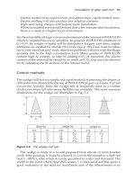
3.0–4.5% are used depending on the application. To take full advantage of
40 80
Gassing time (seconds)
120
5
10
15
20
Compression strength (kg/cm )
2
3.5% Solosil
3.5%
Conventional
silicate
210 Foseco Non-Ferrous Foundryman’s Handbook
the high reactivity, an automatic gassing system incorporating a vaporiser,
pressure regulator, flow controller and gassing timer is advisable. The high
rate of strength development is shown in Fig. 14.3. While the transverse and
tensile strength developed by SOLOSIL binders are still somewhat lower
than some organic resin binders, SOLOSIL generally proves more cost
effective and overcomes problems of poor hot strength, veining and finning,
gas pinholing and fume on casting which occur with some resin binders.
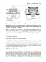
Self-setting sodium silicate processes
The first self-setting process used powder hardeners. The Nishiyama
process used finely ground ferrosilicon powder which reacts with sodium
silicate generating heat and forming a very strong bond. The reaction also
generates hydrogen which is dangerous. Other powder hardeners (which do
not evolve dangerous gases) include di-calcium silicate, certain cements
(such as blast furnace cement and sulphate resisting cement) and anhydrite.
However, all powder hardeners are difficult to add uniformly to sand in
continuous mixers, and their reactivity is difficult to control, since particle
size and the age after grinding affect the reactivity of the powder. When
liquid hardeners based on organic esters were introduced, the use of powder
hardeners was largely discontinued.
Ester silicate process
Foseco products: CARSIL sodium silicate binders
CARSET ester hardener
VELOSET special ester for very rapid setting
Figure 14.3 Strength development of SOLOSIL compared with conventional
sugar/silicate system.
Sodium silicate bonded sand 211
Principle: Sand is mixed with a suitable grade of sodium silicate, often
incorporating a breakdown agent, together with 10–12% (based on silicate)
of liquid organic ester hardener. The acid ester reacts with and gels the
sodium silicate, hardening the sand. The speed of hardening is controlled by
the type of ester used.
Sand: Dry silica sand of AFS 45–60 is usually used. As with all silicate
processes, the quality and purity of the sand is not critical; alkaline sand
such as olivine can be used. Fines should be at a low level. Sand temperature
should be above 15°C; low temperature slows the hardening.
Additions: Sodium silicates with ratios between 2.2 and 2.8 are suitable, the
higher the ratio, the faster the set. Silicates containing breakdown agents are
usually used, additions between 2.5 and 3.5% are used depending on the
sand grade. The ester hardener is commonly:
glycerol diacetate fast cure
ethylene glycol diacetate medium cure
glycerol triacetate slow cure
Proprietary hardeners may be blends of the above with other esters. The
addition level is 10–12% of the silicate.
Pattern equipment: Wood, resin or metal patterns can be used. Core boxes and
patterns should be coated with polyurethane or alkyd paint followed by
application of wax polish. STRIPCOTE parting agent may also be used.
Mixing: Continuous mixers are usually used; if batch mixers are used, the
ester hardener should be mixed with the sand before adding the silicate.
Speed of strip: 20–120 minutes is common with normal ester hardeners.
Attempts to achieve faster setting may result in lower strength moulds
because the work time becomes short. With certain esters there is a tendency
for core and mould distortion due to sagging if stripping occurs too early.
Faster setting can be achieved by using the special VELOSET hardener.
Strength: The final strength achieved is:
Tensile 700 kPa (100 psi)
Compression 2000–5000 kPa (300–700 psi)
Coatings: Spirit-based coatings should be used.
Casting characteristics: No metallurgical problems arise with ferrous or non-
ferrous castings. Breakdown is poor unless a silicate incorporating a
breakdown agent is used.
212 Foseco Non-Ferrous Foundryman’s Handbook
Reclamation: As with all silicate processes, burnout of the bond does not
occur during casting and attrition does not remove all the silicate residue so
that build-up occurs in the reclaimed sand, reducing refractoriness and
leading to loss of control of work time and hardening speed. The VELOSET
system has been specially developed to permit reclamation (see below).
Environment: Silicate and ester have little smell and evolve little fume on
casting. Silicates are caustic so skin and eye protection is needed while
handling mixed sand.
CARSET 500 Hardeners: These are blends of organic esters formulated to give
a wide range of setting speeds when used with sodium silicates, particularly
the GARSIL series of silicates which incorporate a breakdown agent. For the
best results, the silicate addition should be kept as low as possible in relation
to the sand quality and the CARSET hardener maintained at 10% by weight
of the silicate level. The speed of set is dependent on the sand temperature,
silicate ratio and grade of CARSET hardener used.
The CARSET 500 series of hardeners
CARSET 500
series
Gel times (minutes) at 20°C using various CARSIL binders
CARSIL 540
2.2 ratio
CARSIL 513
2.4 ratio
CARSIL 100
2.5 ratio
500 8 7 5
511 9 8 6
522 13 12 8
533 19 15 9
544 105 53 21
555 ––90
Note: The gel time is the time taken for gelling to occur when silicate liquid is mixed with
an appropriate amount of setting agent. The setting times may not be repeated exactly when
sand is present, due to the possibility of impurities, but the figure provides a useful guide.
VELOSET hardeners: The VELOSET range is a series of advanced ester
hardeners for the self-setting silicate process. They have been designed to
give very rapid setting speed with a high strength, excellent through-cure
and a high resistance to sagging. Used in the VELOSET Sand Reclamation
Process, they provide the only ester silicate process in which the sand can be
reclaimed by a simple dry attrition process and reused at high levels equal
to those typical of resin bonded sands.
Sodium silicate bonded sand 213
Additions: There are three grades of VELOSET hardener. VELOSET 1, 2 and
3. Binders of ratio 2.2–2.6 are used; lower ratios give inferior strength while
if higher ratios are used the bench life becomes too short. The bench life
obtained is independent of addition level. The level is usually 10–12% based
on the binder. If the sand is to be reclaimed, the addition level of 11% should
not be exceeded.
Bench life (minutes) at 20°C
CARSIL ratio VELOSET grade
123
2.2 10 7 4
2.4 7 4 2
2.6 4 2 1
When a choice is possible, always use the highest ratio CARSIL binder and
the slowest grade of VELOSET hardener. This provides optimum strength
development.
Mixer: Since VELOSET is rapid setting, it is preferable to use a continuous
mixer.
VELOSET sand reclamation process: With the conventional ester silicate
process, dry attrition reclamation has occasionally been practised but the
level of sand reuse is rarely more than 50%, which hardly justifies the capital
investment involved. With the VELOSET system, up to 90% reuse of sand is
possible using mechanical attrition.
The process stages are:
Crushing the sand to grain size
Drying
Attrition
Classification
Cooling
The reclaimed sand is blended with new sand in the proportion 75 to 25.
During the first 10 cycles of reuse, the sand system stabilises and the bench
life of the sand increases by a factor of up to 2. Also, mould strength should
improve, and it is usually possible to reduce the binder addition level by up
to 20% yet still retaining the same strength as achieved using new sand.
Once the process has become established, it may become possible to reuse
up to 85–90% of the sand, Figs 14.4 and 14.5.
214 Foseco Non-Ferrous Foundryman’s Handbook
Figure 14.4 VELOSET reclamation, showing the variation in bench life after
repeated use of relaimed sand, compared with conventional ester process.
Figure 14.5 VELOSET reclamation, ultimate strength characteristics of reclaimed
sand, compared with conventional ester process.
Sodium silicate bonded sand 215
Adhesives and sealants
It is often necessary to joint cores together to form assemblies, or to glue
cores to moulds before closing the mould. A range of CORFIX adhesives is
available:
CORFIX
grade
Type Set time Temp(°C) Remarks
4 Stove hardening 30 180–220 High viscosity gap
filling
8 Air hardening slow ambient For CO
2
and self-set
silicate
21 Air hardening fast ambient Any cold core
25 Hot melt open time
15–120 sec.
140–180 Core assembly at high
rates, shell process
CORSEAL sealants
This is a group of core sealing or mudding compounds for filling out joint
lines, cracks and minor blemishes in cores. CORSEAL is available in two
forms:
CORSEAL 2 is a powder which is mixed with water to form a thick
paste (4 parts product to 3 parts water). The paste is applied by spatula
or trowel (or fingers) and allowed to dry for about an hour. It may be
lightly torched if required immediately.
CORSEAL 3 and 4 are ready-mixed self-drying putties which are
sufficiently permeable when full dry to prevent blowing but strong
enough to prevent metal penetration into the joint. Drying time
depends on local conditions and the thickness of the layer applied but
should be at least 30 minutes.
TAK sealant
Small variations in the mating faces of moulds due to flexing of patterns or
deformation of moulding boxes and moulding materials may result in gaps
into which liquid metal will penetrate causing runout and flash. This can be
prevented by the application of TAK plastic mould sealant which forms a
metal and gas-tight seal. TAK does not melt at high temperatures and, if
216 Foseco Non-Ferrous Foundryman’s Handbook
metal touches it, it burns to a compact, fibrous mass. The TAK strip is laid
around the upper surface of the drag mould, about 25 mm from the edge of
the mould cavity and the mould is then closed and clamped. TAK can also
be used to seal small core prints:
TAK 3 is supplied in cartridge form for extrusion from a hand gun; a
variety of nozzle sizes is available.
TAK 500 is ready-extruded material supplied in continuous lengths of
6 mm diameter.
Chapter 15
Magnesium casting
Casting alloys
Magnesium alloy castings are used for aerospace, automotive and electronic
applications. Their main advantage is their light weight; typical magnesium
alloys have a density of 1.8 g/ml compared with 2.7 g/ml for aluminium
alloys. Aluminium is the principal alloying constituent of magnesium-based
casting alloys with zinc and manganese also present in small amounts.
Pressure diecasting is the most commonly used casting process and because
of the low casting temperature (650–700°C), hot chamber diecasting
machines can be used. Magnesium diecastings can be made with thinner
walls than aluminium, allowing the overall weight of components to be
substantially reduced and compensating for the higher alloy cost per
kilogram. Gravity diecasting and sand casting are also used, particularly for
more highly stressed castings. The use of high purity alloys with low levels
of Fe, Ni and Cu improves corrosion resistance allowing their use in
automotive applications exposed to road salt. The use of magnesium alloy
diecastings in automotive components is growing rapidly as automobile
companies seek ways of reducing weight. Some vehicles already contain as
much as 10–20 kg of Mg components. The most popular parts made at
present for production cars are: instrument panel substrates, cross car
Table 15.1 Commonly used magnesium alloys
Alloy Characteristics Typical uses
AZ91
AZ81
The most common alloys for
pressure and gravity die and sand
casting
Housings, covers,
brackets, chain saw parts,
hand tools, computer
parts etc.
AM50
AM60
Both alloys combine strength,
ductility castability and cold
workability
Seat frames, instrument
panels, brackets, wheels.
AM20 Used for pressure diecastings
where high ductility and impact
strength are required
Automotive safety parts.
218 Foseco Non-Ferrous Foundryman’s Handbook
beams, seat frames. Wheels, gearbox casings, sumps and inlet manifolds are
used on Formula One and other racing cars.
The most commonly used casting alloys (using the ASTM designation,
which is frequently used) are described in Tables 15.1, 15.2 and 15.3. Mg–
zirconium and Mg–yttrium high strength alloys have been developed and
are used mainly for defence applications.
The melting, treatment and casting of magnesium
alloys
Molten magnesium alloys attack firebrick and refractory furnace linings
resulting in harmful silicon contamination. For this reason, steel crucibles,
pressed or cast, are used. Iron is also slightly soluble in magnesium alloys
but it has a much less harmful effect than silicon. Scrap should be cleaned
and if possible shot-blasted to remove adhering sand as a further precaution
against silicon pick-up. To eliminate ladling, the molten alloy should, if
possible, be poured direct from the melting pot.
Magnesium alloys must be melted under covering and cleansing fluxes, to
avoid oxidation losses and to remove inclusions. Inhibitor powders should
be used to cover exposed metal during holding and pouring, and added to
moulding sand to prevent chemical reaction. Magnesium alloys benefit from
grain refinement which is carried out by inoculating with carbonaceous
materials. Hexachloroethane is effective, decomposing in the liquid metal to
Table 15.2 Composition of magnesium alloys
Composition
Alloy Al Zn Mn Cu Fe Si Ni Total
impurities
AZ91 8.0–9.5 0.3–1.0 0.1–0.3 0.15 0.05 0.3 0.01 0.40
AZ81 7.5–9.0 0.3–1.0 0.15–0.4 0.15 0.05 0.3 0.01 0.40
AM50 4.5–5.3 0.1 0.27min 0.008 0.004 0.1 0.001
AM60 5.7–6.3 0.2 0.27 min 0.008 0.004 0.05 0.001
AM20 1.7–2.2 0.1 0.5 min 0.008 0.004 0.1 0.001
Note: Single figures are maximum %.
High purity versions of AZ91 and AZ81 are frequently used, they have max. Fe 0.004, Ni
0.001, Cu 0.015, Si 0.05, others 0.01 each.
The above figures are intended as a guide only. National specifications may differ and must
be referred to.
Mechanical properties are similar to the commonly used aluminium alloys, Table 15.3.
Magnesium casting 219
Table 15.3 Mechanical properties of magnesium alloys
Typical mechanical properties
Alloy Form Condition TS
(N/mm
2
)
YS
(N/mm
2
)
Elong.
(%)
Brinell
hardness
Melting
range (°C)
AZ91HP Press. die 200–250 150–170 0.5–3.0 65–85 420–600
Grav. die F 160–220 110–130 2–555–70
T4 240–280 120–160 6–10 55–60
T6 240–300 150–190 2–760–90
Sand F 160–220 90–120 2–550–65
T4 240–280 110–140 6–12 55–70
T6 240–300 150–190 2–760–90
AZ81HP Press. die 200–240 140–160 1–360–85 425–615
Grav. die F 160–220 90–110 2–650–65
T4 240–280 90–120 8–12 50–65
Sand F 160–220 90–110 2–650–65
T4 240–280 90–120 8–12 50–65
AM60HP Press. die 190–230 120–150 4–855–70 445–630
Sand F 180–240 80–110 8–12 50–65
T4 190–250 90–110 8–15 50–65
AM50HP Press. die 180–220 110–140 5–950–70 440–625
AM20HP Press. die 160–210 90–120 8–12 40–55
Aluminium alloys for comparison
LM24 Al–Si8Cu3Fe
Press. die F 110 200 2 85
M25 Al–Si7Mg
Grav. die F 180 90 5 60
Sand F 140 90 2.5 60
TE 170 130 1.5 70
Notes: F = as cast
T4 = solution treated
T6 = solution treated and artificially aged
TE = precipitation treated (Al alloy).
The data is intended as a guide only, refer to National Standards for details.
form specks of carbon throughout the melt which act as nuclei for grain
growth. The use of hexachloroethane in aluminium alloy metal treatment
has been banned in Europe for health and safety reasons, although it is still
permitted for grain refining magnesium until alternative treatments have
been developed. Foseco has withdrawn all hexa-containing products from
sale.
220 Foseco Non-Ferrous Foundryman’s Handbook
Melting
MAGREX 60 flux is used as a covering and cleansing flux; it provides a
liquid surface cover during melting which prevents contact with the air so
that melting losses are reduced and burning prevented. It also has a
scavenging action which removes non-metallic impurities.
Table 15.4 Magnesium–Zirconium alloys
Alloy (ASTM) Zn RE metals Zr Cu Ni
ZK51 3.5–5.5 – 0.4–1.0 0.03 0.005
ZE41 3.5–5.5 0.75–1.75 0.4–1.0 0.03 0.005
EZ33 0.8–3.0 2.5–4.0 0.4–1.0 0.03 0.005
Note: Single figures are maximum %.
Mechanical properties:
Alloy Form Tensile
strength
(MPa)
Elongation
(%)
Properties
ZK51 Sand cast 230 5 High strength, good ductility
Chill cast 245 7
ZE41 Sand cast 200 3 High strength, pressure-tight
Chill cast 215 4
EZ33 Sand cast 140 3 Pressure-tight at high
Chill cast 155 3 temperature
Table 15.5 Magnesium–yttrium alloys
Alloy
(ASTM)
Zn RE* Zr Cu Ni Fe Si Mn Yt TS
(MPa)
Elong.
WE54 0.2 2.0–4.0 0.4–1.0 0.03 0.005 0.01 0.01 0.15 4.75–5.5 250 2%
WE43 0.2 2.4–4.4 0.4–1.0 0.03 0.005 0.01 0.01 0.15 3.7–4.3 250 2%
*Neodynium and heavy rare earths.
WE54 has good strength up to 300°C for short times.
WE43 has good strength up to 250°C for long times.
Magnesium casting 221
A little MAGREX 60 is dusted into the bottom of a heated, pressed steel
crucible. The ingot and scrap are then charged on top and a further addition
of MAGREX made. The total application should be approximately 1% of the
charge weight. Melt down rapidly, maintaining a good cover at all times.
At about 750°C the heat should be stopped, the crucible sides scraped and
the melt skimmed. A further 2% addition of MAGREX is then made and
rabbled in well with a perforated plunger. More MAGREX is added
progressively and stirred until the metal surface, which previously had a
frothy appearance, becomes bright. As the MAGREX absorbs oxides and
impurities, its density increases until it sinks to the bottom of the crucible.
During the time the melt is cooling to the correct temperature, it should be
skimmed and the cleaned area immediately dusted with an inhibitor
powder, such as “flowers of sulphur”, to prevent burning. Pour carefully,
dusting the metal stream as it enters the mould with sulphur to prevent
oxidation. Care must be taken to keep back any slag and particularly when
nearing the end of the pour, to prevent any sludge entering the mould.
Remove the sludge from the bottom of the pot and thoroughly scrape the
sides and bottom before returning it to the furnace for recharging.
Use of sulphur hexafluoride
Fluxless melting of Mg alloys requires another form of melt protection.
Sulphur hexafluoride, SF
6
, is a colourless, odourless gas having low toxicity.
At low concentrations, for example less than 0.8% in air or air/CO
2
, it
promotes the formation of a protective film on liquid magnesium which
prevents oxidation. SF
6
, like other fluorine-containing gases, is a “green-
Table 15.6 Use of sulphur hexafluoride in pressure diecasting operations
Melt
temp. (°C)
Recommended atmosphere
over the melt (vol %)
Surface
agitation
Operating conditions
Residual
flux**
Melt
protection
650–705 air + 0.04 SF
6
* No No Excellent
650–705 air + 0.2 SF
6
Yes No Excellent
650–705 75 air + 25 CO
2
+ 0.2 SF
6
Yes Yes Excellent
705–760 50 air + 50 CO
2
+ 0.3 SF
6
Yes No Excellent
705–760 50 air + 50 CO
2
+ 0.3 SF
6
Yes Yes Very good
*Minimum concentration under controlled conditions.
**May be present from prior operations.
Note: High humidity either in the outer atmosphere surrounding the melt or in the air
blended with the SF
6
/CO
2
will reduce the effectiveness of SF
6
. Dry air (less than 0.1% H
2
O
by volume) should be used in the mixing.
222 Foseco Non-Ferrous Foundryman’s Handbook
house gas” considered harmful to the atmosphere and its use must be
minimised. The most common gases used in fluxless melting are SF
6
mixed
with dry air and some CO
2
. The recommended protective atmospheres
under various operating conditions are shown in Tables 15.6 and 15.7 taken
from data provided by the International Magnesium Association.
The concentrations in Tables 15.6 and 15.7 should be maintained close to
the melt surface. A gas mixing unit is recommended to control both the flow
rate and the concentration of the gas. The protective atmosphere should be
supplied through a manifold with several outlet nozzles positioned to
supply gas to the whole surface of the melt. The furnace cover design is
important for conservation of SF
6
.
Casting temperature
Light castings, under 15 mm 780–810°C
Medium castings, 15–40 mm 760°C
Heavy castings, over 40 mm 730°C
Use of inhibitors in moulding sand
A chemical inhibitor must be added to moulding sand to prevent reaction
between the molten magnesium and the moisture present in the green sand.
Several materials can be used including sulphur, boric acid or ammonium
bifluoride, used singly or together. The amount needed varies, depending
on the moisture content of the sand and section thickness of the casting.
Generally, however, 4–6% sulphur with 0.5% boric acid is used or up to 2%
of ammonium bifluoride alone.
Table 15.7 Use of sulphur hexafluoride in gravity casting operations (up
to 830°C)
Crucible
diameter
Quiescent (melting/holding)
low gas flow rate
SF
6
(ml/min.) CO
2
(l/min.)
Agitated (alloying/pouring) high
gas flow rate
SF
6
(ml/min.) CO
2
(l/min.)
30 cm 60 3.5 200 10
50 cm 60 3.5 550 30
75 cm 90 5 900 50
Note: These suggested flow rates are 1.7%–2% SF
6
by volume. The use of SF
6
/CO
2
atmospheres for melting yttrium-containing alloys can lead to yttrium loss by preferential
oxidation by CO
2
. Argon/SF
6
atmospheres are recommended for these alloys during
melting and holding.
Magnesium casting 223
Recovering and refining magnesium
MAGREX 60 flux is suitable for the melting and refining of magnesium alloy
foundry returns and turnings. 5–10% of MAGREX 60 is prefused in the
melting unit and the dry scrap gradually added through the flux. After all
the additions have been made and the melt is at 700–750°C, a further 2% of
flux is fused on the melt before rabbling well into the metal for 3 to 5
minutes. The cleansed metal is then decanted off the spent flux. After
pouring, the spent flux and impurities are scraped from the sides and
bottom of the melting unit.
Foundry tools can be cleansed by immersing them in molten MAGREX 60
flux for a few minutes. This will absorb any adhering metal oxides and leave
them clean and ready for use.
Running and gating
Since magnesium alloys oxidise rapidly, every effort should be made to
ensure non-turbulent pouring. Use of SIVEX FC or STELEX ceramic foam
filters to remove oxide films is recommended (see Chapter 8). As
magnesium is so light, a pouring basin should be built up above the top
surface of the mould to provide greater metallostatic pressure. Running and
feeding methods should be as for a moderately high shrinkage alloy, e.g.
fairly large diameter runners and large feeding heads with KALMIN
insulating sleeves.
Gravity diecasting
Magnesium alloys are so light in weight that little metallostatic pressure is
available to displace mould air and the possibility of short runs or cold shuts
is enhanced. Dies should be designed with ample venting and down-sprues
should be large in area relative to aluminium practice. The minimum wall
thickness of castings should be 5 mm. Die coatings are the same as for
aluminium alloys.
The alloy for diecasting is frequently melted in a fully enclosed bale-out
furnace under an inert atmosphere of sulphur dioxide or sulphur hexa-
fluoride gas mixtures (Table 15.7). MAGREX 60 is used. As it becomes
impregnated with oxides, it sinks to the bottom of the melt. When the metal
bath is at a temperature of 720–750°C, about 3% of MAGREX is introduced.
As the charge is replenished from time to time, more MAGREX is added.
The flux cover is stirred from 3 to 4 minutes until the alloy surface is bright.
The spent flux must be removed from the bottom of the furnace daily.
Pressure diecasting
Mg alloys can be diecast using both cold chamber and hot chamber
machines. Hot chamber machines are so called because they use a pump
224 Foseco Non-Ferrous Foundryman’s Handbook
submerged in the molten alloy to fill the die and apply the required pressure
during solidification, the cold chamber machines require a measured
quantity of molten metal to be transferred from a holding furnace to the
machine for each shot. The hot chamber process can achieve higher
production rates and the castings produced are generally more consistent.
Pressure diecasting is the most frequently used process for automotive
castings, where the growth in usage is high because of the attraction of
weight reduction. Potential magnesium components and their estimated
weights are shown in Table 15.8 (reproduced by courtesy of Buhler Ltd).
The usage of magnesium diecastings is expected to increase from 51 000
tonnes in 1996 to 186 000 tonnes in the year 2006.
Table 15.8 Estimated weight of diecast magnesium automotive
components
Component Estimated weight for a mid-size car (kg.)
Dashboards 3.0–5.0
Bumper holders 2.5–4.5
Holders and supports 1.0–2.0
Front seat frames 18.0–24.0
Electronic circuitry cases 0.2–0.7
Gearboxes 8.0–12.0
Cylinder head covers 0.5–1.2
Oil sumps 0.8–1.2
Pedal supports 1.0–1.8
Wheels 14.0–26.0
Steering wheels 0.3–0.5
Chapter 16
Copper and copper alloy
castings
The main copper alloys and their applications
1 High conductivity coppers. Used chiefly for their high electrical and
thermal conductivities. Applications include tuyeres for blast furnaces
and hot blast cupolas, water-cooled electrode clamps, switchgear etc.
2 Brasses; copper–zinc alloys where zinc is the major alloying element.
Easy to cast, with excellent machinability and good resistance to
corrosion in air and fresh water. They are widely used for plumbing
fittings. High tensile brasses are more highly alloyed and find uses in
marine engineering.
3 Tin bronzes; copper–tin alloys where tin is the major alloying element.
With tin contents of 10–12%, tin bronze castings are more expensive
than brass. They have high corrosion resistance and are suitable for
handling acidic waters, boiler feed waters etc. High tin alloys are also
used in wear-resistant applications.
4 Phosphor bronzes; copper–tin alloys with an addition of about 0.4–1.0%
P. They are harder than tin bronzes but with lower ductility. They are
used for bearings where loads and running speeds are high and for
gears such as worm wheels.
5 Lead bronzes; copper–tin–lead alloys. Used almost exclusively for
bearings, where loads and speeds are more moderate.
6 Gunmetals; copper–tin–zinc–lead alloys. Favourite alloys for sand
casting. They have a good combination of castability, machinability and
strength with good corrosion resistance. They are used for intricate,
pressure-tight castings such as valves and pumps. Also for bearings
where loads and speeds are moderate.
7 Aluminium bronzes; copper–aluminium alloys where Al is the major
alloying element. They combine high strength with high resistance to
corrosion. Applications range from decorative architectural features to
highly stressed engineering components. They have many marine uses
including propellers, pumps and valves and are used for the manu-
facture of non-sparking tools.
226 Foseco Non-Ferrous Foundryman’s Handbook
8 Copper–nickels; copper–nickel alloys where Ni is the major alloying
element. Used for marine applications in severe conditions, for example
for pipework.
(The above information is based on data kindly supplied by the Copper
Development Association, St Albans, Herts.)
Specifications for copper-based alloys
The new BS EN 1982 standard for Copper and Copper Alloy Ingots and
Castings is the British implementation of the European Standard and it
replaces BS 1400:1985 which has been withdrawn. BS 1400 used abbrevia-
tions of the type of material:
SCB sand casting brass
DCB diecasting brass
HTB high tensile brass
DZR dezincification resistant brass
HCC high conductivity copper
CC copper–chromium
CT copper–tin (bronze)
PB phosphor bronze
LB leaded bronze
LG leaded gunmetal
G gunmetal
AB aluminium bronze
CMA copper–manganese–aluminium
CN copper–nickel
These have been superseded in the European Standard by compositional
designations with the base metal first followed by the major alloying
elements, e.g. CuZn33Pb2-C is a leaded brass casting alloy containing 33%
Zn and 2% Pb. Two further letters are used to designate the relevant casting
process which affects the mechanical properties:
GM permanent mould casting
GS sand casting
GZ centrifugal casting
GP pressure diecasting
GC continuous casting
Note that there is not necessarily an exact equivalence between the BS 1400
alloy and the corresponding BS EN alloy. The European Standard also uses
Copper and copper alloy castings 227
a Material Designation Number for each casting alloy so the leaded brass
referred to above is designated:
CuZn33Pb2-C Number CC750S and is equivalent to the old BS 1400
sand casting brass SCB3.
Table 16.1 lists the BS EN 1982 alloys and the nearest BS1400 equivalent
alloys which they replace.
Table 16.2 lists the compositions and mechanical properties of the
alloys.
Thanks are due to the Copper Development Association (Verulam
Industrial Estate, 224 London Road, St Albans, Herts AL1 1AQ, England) for
providing the information in Tables 16.1 and 16.2.
Colour code for ingots
In the UK, the following system was used for colour coding of ingots.
Designation Colour code Designation Colour code
Group A Group B
PB4 Black/red PB1 Yellow
LPB1 Black PB2 Yellow/red
LB2 White CT1 Black/aluminium
LB4 White/green LB5 White/brown
LG2 Blue LG1 Blue/red
LG4 Blue/brown AB1 Aluminium
SCB1 Green/blue AB2 Aluminium/green
SCB3 Green CMA1 Aluminium/red
SCB6 Green/brown CMA2 Aluminium/yellow
DCB1 Yellow/blue HTB1 Brown
DCB3 Yellow/brown HTB3 Brown/red
PCB1 White/blue
Group C
LB1 White/black
G3 Blue/black
SCB4 Green/yellow
G1 Red
Note: Group A are alloys in common use.
Group B are special purpose alloys.
Group C are alloys in limited production.