GasTurbine Engineering HandbookSecond Edition phần 5 potx
Bạn đang xem bản rút gọn của tài liệu. Xem và tải ngay bản đầy đủ của tài liệu tại đây (1.38 MB, 82 trang )
//INTEGRA/B&H/GTE/FINAL (26-10-01)/CHAPTER 7.3D ± 313 ± [275±318/44] 29.10.2001 4:00PM
The losses as mentioned earlier can be further described:
1. Disc friction loss. This loss is from skin friction on the discs that house
the blades of the compressors. This loss varies with different types of
discs.
2. Incidence loss. This loss is caused by the angle of the air and the blade
angle not being coincident. The loss is minimum to about an angle of
Æ4
, after which the loss increases rapidly.
3. Blade loading and profile loss. This loss is due to the negative velocity
gradients in the boundary layer, which gives rise to flow separation.
4. Skin friction loss. This loss is from skin friction on the blade surfaces
and on the annular walls.
5. Clearance loss. This loss is due to the clearance between the blade tips
and the casing.
6. Wake loss. This loss is from the wake produced at the exit of the
rotary.
7. Stator profile and skin friction loss. This loss is from skin friction and
the attack angle of the flow entering the stator.
8. Exit loss. This loss is due to the kinetic energy head leaving the stator.
Figure 7-33 shows the various losses as a function of flow. Note that the
compressor is more efficient as the flow nears surge conditions. Figure 7-34
also shows a typical axial-flow compressor map. Note the steepness of the
constant speed lines as compared with a centrifugal compressor. The axial-
flow compressor has a much smaller operating range than its counterpart in
the centrifugal compressor.
Stall Analysis of an Axial-Flow Compressor
A typical vibration analyis identified a surge condition in the fifth stage of
an axial compressor. A pressure transducer with a voltage output was used
to obtain the frequency spectra. In the first four stages of the compressor, no
outstanding vibration amplitudes were recorded. A signal was noted at 48N
(N being the running speed), but the amplitude was not high, and it did not
fluctuate. A measurement at the low-pressure bleed chamber taken from the
fourth stage showed similar characteristics. The compressor high-pressure
bleed chamber occurs after the eighth stage. A measurement at this chamber
showed a high, fluctuating 48N signal. As there are 48 blades on the fifth-
stage wheel, a problem in the fifth stage was suspected. However, above the
fifth stage are blade rows of 86N (2 Â 48N), so the analysis was not clearcut.
It was found that the measurement at the high-pressure bleed chamber
Axial-Flow Compressors 313
//INTEGRA/B&H/GTE/FINAL (26-10-01)/CHAPTER 7.3D ± 314 ± [275±318/44] 29.10.2001 4:00PM
showed only a very small 86N amplitude compared to the high amplitude of
the 48N frequency. Since blade rows of 86 blades were closer to the high-
pressure bleed chamber, the expected high signal should have been 86N
compared to 48N under normal operating conditions. This high amplitude
Figure 7-33. Losses in an axial-flow compressor stage.
Figure 7-34. Performance map of an axial-flow compressor.
314 Gas Turbine Engineering Handbook
//INTEGRA/B&H/GTE/FINAL (26-10-01)/CHAPTER 7.3D ± 315 ± [275±318/44] 29.10.2001 4:00PM
of 48N indicated that it was the fifth stage that caused the high, fluctuating
signal; thus, a stall condition in that section was probable. Figures 7-35,
7-36, 7-37, and 7-38 show the spectrum at speeds of 4100, 5400, 8000, and
9400 rpm. At 9400 rpm, the second and third harmonics of 48N were also
very predominant.
Next, the fifth-stage pressure was measured. Once again, a high amplitude
at 48N was found. However, a predominant reading was also observed at
1200 Hz frequency. Figures 7-39 and 7-40 show the largest amplitudes at
speeds of 5800 and 6800 rpm, respectively.
At the compressor exit, predominate frequencies of 48N existed up to
speeds of 6800 rpm. At 8400 rpm, the 48N and 86N frequencies were of
about equal magnitudesÐthe only signal where the 48N and 86N frequen-
cies were the same. The pressure was measured from a static port in the
Figure 7-35. High-pressure bleed chamberÐ4100 rpm.
Figure 7-36. High-pressure bleed chamberÐ5400 rpm.
Axial-Flow Compressors 315
//INTEGRA/B&H/GTE/FINAL (26-10-01)/CHAPTER 7.3D ± 316 ± [275±318/44] 29.10.2001 4:00PM
Figure 7-37. High-pressure bleed chamberÐ8000 rpm.
Figure 7-38. High-pressure bleed chamberÐ9400 rpm.
Figure 7-39. Fifth-stage bleed pressureÐ5800 rpm.
316 Gas Turbine Engineering Handbook
//INTEGRA/B&H/GTE/FINAL (26-10-01)/CHAPTER 7.3D ± 317 ± [275±318/44] 29.10.2001 4:00PM
chamber. All other pressures were measured from the shroud, thus indicat-
ing the phenomena occurred at the blade tip. Since the problem was isolated
to the fifth stage, the conclusion was that the stall occurred at the fifth-stage
rotor tip. A subsequent inspection confirmed the suspicion when cracks at
the blade hubs were noticed.
Bibliography
Boyce, M.P., ``Transonic Axial-Flow Compressor,'' ASME Paper No. 67-GT-47.
Boyce. M.P., ``Fluid Flow Phenomena in Dusty Air,'' (Thesis), University of
Oklahoma Graduate College, 1969, p. 18.
Boyce. M.P., Schiller, R.N., and Desai, A.R., ``Study of Casing Treatment
Effects in Axial-flow Compressors,'' ASME Paper No. 74-GT-89.
Boyce, M.P., ``Secondary Flows in Axial-flow Compressors with Treated Blades,''
AGARD-CCP-214 pp. 5-1 to 5-13, 1974.
Carter, A.D.S., ``The Low-Speed Performance of Related Aerofoils in Cascade,''
Rep. R.55, British NGTE, September, 1949.
Giamati, C.C., and Finger, H.B., ``Design Velocity Distribution in Meridional
Plane,'' NASA SP 36, Chapter VIII (1965), p. 255.
Graham, R.W. and Guentert, E.C., ``Compressor Stall and Blade Vibration,''
NASA SP 36, (1965) Chapter XI, p. 311.
Hatch. J.E., Giamati, C.C., and Jackson, R.J., ``Application of Radial Equili-
brium Condition to Axial-Flow Turbomachine Design Including Considera-
tion of Change of Enthropy with Radius Downstream of Blade Row,'' NACA
RM E54A20 (1954).
Herrig, L.J., Emery, J.C., and Erwin, J.R., ``Systematic Two-Dimensional
Cascade Tests of NACA 65 Series Compressor Blades at Low Speed,''
NACA R.M. E 55Hll (1955).
Figure 7-40. Fifth-stage bleed pressureÐ6800 rpm.
Axial-Flow Compressors 317
//INTEGRA/B&H/GTE/FINAL (26-10-01)/CHAPTER 7.3D ± 318 ± [275±318/44] 29.10.2001 4:00PM
Holmquist, L.O., and Rannie, W.D., ``An Approximate Method of Calculating
Three-Dimensional Flow in Axial Turbomachines'' (Paper) Meeting Inst.
Aero. Sci., New York, January 24
Â
±28, 1955.
Horlock, J.H., ``Axial Flow Compressors,'' Robert E. Krieger Publishing
Company, 1973.
Koller, U., Monig, R., Kosters, B., Schreiber, H-A, 1999, ``Development of
Advanced Compressor Airfoils for Heavy-Duty Gas Turbines. Part I: Design
and Optimization,'' ASME 99-GT-95.
Lieblein, S., Schwenk, F.C., and Broderick, R.L., ``Diffusion Factor for Estim-
ating Losses and Limiting Blade Loading in Axial-Flow Compressor Blade
Elements,'' NACA RM #53001 (1953).
Mellor, G., ``The Aerodynamic Performance of Axial Compressor Cascades with
Application to Machine Design,'' (Sc. D. Thesis), M.I.T. Gas Turbine Lab,
M.I.T. Rep. No. 38 (1957).
Stewart, W.L., ``Investigation of Compressible Flow Mixing Losses Obtained
Downstream of a Blade Row,'' NACA RM E54120 (1954).
318 Gas Turbine Engineering Handbook
//SYS21///INTEGRA/B&H/GTE/FINAL (26-10-01)/CHAPTER 8.3D ± 319 ± [319±336/18] 29.10.2001 4:01PM
8
Radial-Inflow Turbines
The radial-inflow turbine has been in use for many years. It first appeared
as a practical power-producing unit in the hydraulic turbine field. Basically a
centrifugal compressor with reversed flow and opposite rotation, the radial-
inflow turbine was the first used in jet engine flight in the late 1930s. It was
considered the natural combination for a centrifugal compressor used in the
same engine. Designers thought it easier to match the thrust from the two
rotors and that the turbine would have a higher efficiency than the com-
pressor for the same rotor because of the accelerating nature of the flow.
The performance of the radial-inflow turbine is now being investigated
with more interest by the transportation and chemical industries: in trans-
portation, this turbine is used in turbochargers for both spark ignition and
diesel engines; in aviation, the radial-inflow turbine is used as an expander in
environmental control systems; and in the petrochemical industry, it is used
in expander designs, gas liquefaction expanders, and other cryogenic sys-
tems. Radial-inflow turbines are also used in various small gas turbines to
power helicopters and as standby generating units.
The radial-inflow turbine's greatest advantage is that the work produced
by a single stage is equivalent to that of two or more stages in an axial
turbine. This phenomenon occurs because a radial-inflow turbine usually
has a higher tip speed than an axial turbine. Since the power output is a
function of the square of the tip speed (PU
2
) for a given flow rate, the work
is greater than in a single-stage axial-flow turbine.
The radial-inflow turbine has another advantage: its cost is much lower
than that of a single or multistage axial-flow turbine. The radial-inflow
turbine has a lower turbine efficiency than the axial-flow turbine; how-
ever, lower initial costs may be an incentive to choosing a radial-inflow
turbine.
319
//SYS21///INTEGRA/B&H/GTE/FINAL (26-10-01)/CHAPTER 8.3D ± 320 ± [319±336/18] 29.10.2001 4:01PM
The radial-inflow turbine is especially attractive when the Reynolds num-
ber R
e
UD=becomes low enough (R
e
10
5
À10
6
) that the efficiency
of the axial-flow turbine is below that of a radial-inflow turbine, as shown in
Figure 8-1. The effect of specific speed N
s
N
Q
p
=H
3=4
ÀÁ
and specific
diameter D
s
DH
1=4
=
Q
p
ÀÁ
on the efficiency of a turbine is shown in Figure
8-2. Radial-inflow turbines are more efficient at a Reynolds number between
10
5
and 10
6
and specific speeds below N
s
10.
Description
The radial-inflow turbine has many components similar to those of a
centrifugal compressor. However, the names and functions differ. There
are two types of radial-inflow turbines: the cantilever radial-inflow turbine
and the mixed-flow radial-inflow turbine. Cantilever blades are often two-
dimensional and use nonradial inlet angles. There is no acceleration of the
Figure 8-1. Influence of Reynolds number on turbine stage efficiency.
320 Gas Turbine Engineering Handbook
//SYS21///INTEGRA/B&H/GTE/FINAL (26-10-01)/CHAPTER 8.3D ± 321 ± [319±336/18] 29.10.2001 4:01PM
flow through the rotor, which is equivalent to an impulse or low-reaction
turbine. The cantilever-type radial-inflow turbine is infrequently used
because of low efficiency and production difficulties. This type of turbine
also has rotor blade flutter problems.
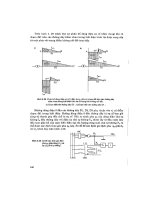
The radial-inflow turbine can be the cantilever type as shown in Figure 8-3,
or the mixed-flow type as shown in Figure 8-4. The mixed-flow radial-inflow
turbine is a widely used design. Figure 8-5 shows the components. The scroll
or collector receives the flow from a single duct. The scroll usually has a
decreasing cross-sectional area around the circumference. In some designs
the scrolls are used as vaneless nozzles. The nozzle vanes are omitted for
economy to avoid erosion in turbines where fluid or solid particles are
trapped in the air flow. Frictional flow losses in vaneless designs are greater
than in vaned nozzle designs because of the nonuniformity of the flow and
the greater distance the accelerating air flow must travel. Vaneless nozzle
configurations are used extensively in turbochargers where efficiency is not
important, since in most engines the amount of energy in the exhaust gases
far exceeds the energy needs of the turbocharger.
Figure 8-2. N
s
D
s
diagram for a turbine stage. Efficiency is on a total-to-total basis;
that is, it is related to inlet and exit stagnation conditions. Diagram values are suitable
for machine Reynolds number R
e
! 10
6
. (Balje, O.E., ``A Study of Reynolds Number
Effects in Turbomachinery,'' Journal of Engineering for Power, ASME Trans., Vol. 86,
Series A, p. 227.)
Radial-Inflow Turbines 321
//SYS21///INTEGRA/B&H/GTE/FINAL (26-10-01)/CHAPTER 8.3D ± 322 ± [319±336/18] 29.10.2001 4:01PM
Figure 8-3. Cantilever-type radial-inflow turbine.
Figure 8-4. Mixed-flow-type radial-inflow turbine.
322 Gas Turbine Engineering Handbook
//SYS21///INTEGRA/B&H/GTE/FINAL (26-10-01)/CHAPTER 8.3D ± 323 ± [319±336/18] 29.10.2001 4:01PM
The nozzle blades in a vaned turbine design are usually fitted around the
rotor to direct the flow inward with the desired whirl component in the inlet
velocity. The flow is accelerated through these blades. In low-reaction tur-
bines the entire acceleration occurs in the nozzle vanes.
The rotor or impeller of the radial-inflow turbine consists of a hub, blades,
and in some cases, a shroud. The hub is the solid axisymmetrical portion of
the rotor. It defines the inner boundary of the flow passage and is sometimes
called the disc. The blades are integral to the hub and exert a normal force on
the flow stream. The exit section of the blading is called an exducer and it is
constructed separately like an inducer in a centrifugal compressor. The
exducer is curved to remove some of the tangential velocity force at the
outlet.
The outlet diffuser is used to convert the high absolute velocity leaving the
exducer into static pressure. If this conversion is not done, the efficiency of
the unit will be low. This conversion of the flow to a static head must be done
carefully, since the low-energy boundary layers cannot tolerate great adverse
pressure gradients.
Theory
The general principles of energy transfer in a radial-inflow turbine are
similar to those already outlined in the compressor section. Figure 8-6 shows
the velocity vectors in turbine rotor flow.
The Euler turbine equation previously defined holds for flow in any
turbomachine
H
1
g
c
U
3
V
3
À U
4
V
4
8-1
Figure 8-5. Components of a radial-inflow turbine.
Radial-Inflow Turbines 323
//SYS21///INTEGRA/B&H/GTE/FINAL (26-10-01)/CHAPTER 8.3D ± 324 ± [319±336/18] 29.10.2001 4:01PM
It may be written in terms of the absolute and relative velocities
H
1
2g
c
U
3
À U
2
4
ÀÁ
V
2
3
À V
2
4
ÀÁ
W
2
4
À W
2
3
ÀÁÂÃ
8-2
For a positive power output, the blade tip speed and whirl velocity
combination at the inlet must be greater than at the exit. From Equation
(8-2), the flow must be radially inward so that centrifugal effects may be
used. The velocity exiting from a turbine is considered to be unrecoverable;
therefore, the utilization factor is defined as the ratio of the total head to the
total head plus the absolute exit velocity.
H
H
1
2
V
2
4
ÀÁ
8-3
Figure 8-6. Velocity vectors in turbine rotor flow.
324 Gas Turbine Engineering Handbook
//SYS21///INTEGRA/B&H/GTE/FINAL (26-10-01)/CHAPTER 8.3D ± 325 ± [319±336/18] 29.10.2001 4:01PM
The relative proportions of energy transfers obtained by a change of static
and dynamic pressure are used to classify turbomachinery. The parameter
used to describe this relationship is called the degree of reaction. Reaction, in
this case, is energy transfer by means of a change in static pressure in a rotor
to the total energy transfer in the rotor
R
1
2g
U
3
2
À U
4
2
ÀÁ
W
4
2
À W
3
2
ÀÁÂÃ
H
8-4
The overall efficiency of a radial-inflow turbine is a function of efficiencies
from various components such as the nozzle and rotor. A typical turbine
expansion enthalpy/entropy diagram is shown in Figure 8-7. The total
enthalpy remains constant through the nozzle, since neither work nor heat
is transferred to or from the fluid. Within the rotor, the total enthalpy
changes. Downstream of the rotor the total enthalpy remains constant.
Figure 8-7. h-s diagram for turbine stage process.
Radial-Inflow Turbines 325
//SYS21///INTEGRA/B&H/GTE/FINAL (26-10-01)/CHAPTER 8.3D ± 326 ± [319±336/18] 29.10.2001 4:01PM
Total pressure decrease in the nozzle and outlet diffuser are only from
frictional losses. In an ideal nozzle or diffuser the total pressure drop is zero.
Isentropic efficiency is defined as the ratio of the actual work to the isen-
tropic enthalpy decrease, which is the expansion from the inlet total pressure
to the outlet total pressure
is
h
0i
À h
05
h
0i
À h
05
is
8-5
The nozzle efficiency can be calculated as shown in the following relation-
ship:
noz
h
0i
À h
2
h
0i
À h
2is
8-6
The rotor efficiency can be defined as shown in the following relationship:
rotor
h
0i
À h
4
h
0i
À h
4is
8-7
Similar to the concept of small-stage efficiency in a compressor, the poly-
tropic efficiency in a turbine is the small-stage efficiency in a turbine. The
isentropic efficiency can be written in terms of the total pressure as follows:
is
1 À
P
05
P
oi
nÀ1
n
1 À
P
05
P
oi
À1
8-8
where P=
n
equals constant and represents the polytropic process for any
particular expansion process. The polytropic efficiency can be written
poly
dh
0act
dh
0isen
1 À 1 À
n À1
n
ÁP
o
P
oi
; FFF;
!
1 À 1 À
À 1
ÁP
oi
P
oi
; FFF;
!
n À1
n
0
À 1
8-9
326 Gas Turbine Engineering Handbook
//SYS21///INTEGRA/B&H/GTE/FINAL (26-10-01)/CHAPTER 8.3D ± 327 ± [319±336/18] 29.10.2001 4:01PM
The polytropic efficiency in a turbine can be related to the isentropic
efficiency and obtained by combining the previous two equations
is
1 À
P
05
P
oi
poly
À1
1 À
P
05
P
oi
À1
8-10
or
poly
1n 1 À
is
is
P
05
P
oi
À1
45
À 1
1n
P
05
P
oi
8-11
Figure 8-8. Relationship between polytropic and isentropic efficiency during
expansion.
Radial-Inflow Turbines 327
//SYS21///INTEGRA/B&H/GTE/FINAL (26-10-01)/CHAPTER 8.3D ± 328 ± [319±336/18] 29.10.2001 4:01PM
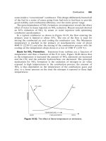
The relationship between the two efficiencies is plotted in Figure 8-8. The
multistage turbine on an enthalpy/entropy diagram is shown in Figure 8-9.
Examining the characteristic of the multistage unit, the isentropic enthalpy
decrease of the incremental stages as compared to the isentropic enthalpy
decrease of a single, whole stage encompassing the multistages is defined as
the reheat factor. Since the pressure lines diverge as entropy increases, the
sum of the small-stage isentropic decreases are somewhat greater than the
overall isentropic decrease for the same pressure. Hence, the reheat factor is
greater than unity, and the turbine's isentropic efficiency is greater than its
polytropic efficiency of the turbine.
The reheat factor can be given
R
f
isen
poly
8-12
Figure 8-9. Enthalpy-entropy diagram for a multistage turbine.
328 Gas Turbine Engineering Handbook
//SYS21///INTEGRA/B&H/GTE/FINAL (26-10-01)/CHAPTER 8.3D ± 329 ± [319±336/18] 29.10.2001 4:01PM
Turbine Design Considerations
To design a radial-inflow turbine of the highest efficiency, the exit velocity
leaving the turbine must be axial. If the exit velocity is axial, the Euler
turbine equation reduces to
H U
3
V
3
8-13
since V
4
0 for an axial outlet velocity.
The flow entering the rotor of a radial-inflow turbine must have a certain
incidence angle corresponding to the ``slip flow'' in a centrifugal impeller and
not to zero incidence. By relating this concept to the radial-inflow turbine,
the following relationship can be obtained for the ratio of whirl velocity to
blade tip speed:
V
3
U
3
1 À
2
B
D
3
D
3
À D
4
!
8-14
This ratio is usually in the neighborhood of 0.8. A ratio of D
3
=D
4
for
radial-inflow rotors is around 2.2, and
B
is the number of blades.
With the aid of the previous relationships, a velocity diagram for the flow
entering a radial-inflow turbine can be drawn as shown in Figure 8-10.
The variation in stage efficiency can be shown as a function of the tip
speed ratio. The tip speed ratio is a function of the blade speed and the
theoretical spouting velocity if the entire enthalpy drop takes place in the
nozzle as given by the following equation:
U
V
o
8-15
where
V
o
2g
c
JÁH
o
p
Figure 8-11 shows the efficiency variation with the tip speed ratio. This
curve also shows the runaway speed. Runaway speed is achieved when
turbine torque falls to zero at blade speeds higher than the design speed. If
failure occurs above the tip speed, the rotor can be defined as a fail-safe rotor
design.
Radial-Inflow Turbines 329
//SYS21///INTEGRA/B&H/GTE/FINAL (26-10-01)/CHAPTER 8.3D ± 330 ± [319±336/18] 29.10.2001 4:01PM
The inlet area at the blade tip can be calculated using the continuity
equation
A
3
D
3
b
3
À
B
t
3
b
3
m
V
3
cos
3
8-16
where b
3
is the blade height and t
3
the blade thickness.
At the exit of the turbine, the absolute exit velocity is axial. Since the blade
speed varies at the exit from hub to shroud, a series of blade diagrams are
obtained as shown in Figure 8-12.
Losses in a Radial-Inflow Turbine
Losses in a radial-inflow turbine are similar to those in a centrifugal
impeller. The losses can be divided into two categories: internal losses
and external losses. Internal losses can be divided into the following
categories:
1. Blade loading or diffusion loss. This loss is due to the type of loading in
an impeller. The increase in momentum loss comes from the rapid
increase in boundary-layer growth when the velocity close to the wall
is reduced. This loss varies from around 7% at a high-flow setting to
about 12% at a low-flow setting.
Figure 8-10. Velocity triangles for a radial-inflow turbine.
330 Gas Turbine Engineering Handbook
//SYS21///INTEGRA/B&H/GTE/FINAL (26-10-01)/CHAPTER 8.3D ± 331 ± [319±336/18] 29.10.2001 4:01PM
2. Frictional loss. Frictional loss is due to wall shear forces. This loss
varies from about 1
Â
±2% as the flow varies from a low-flow to a high-
flow setting.
3. Secondary loss. This loss is caused by the movement of the boundary
layers in a direction different from the main stream. This loss is small
in a well-designed machine and is usually less than 1%.
4. Clearance loss. This loss is caused by flow passing between the
stationary shroud and the rotor blades and is a function of the blade
height and clearance. The clearance is usually fixed by tolerances and,
for smaller blade heights, the loss is usually a greater percentage. This
loss varies between 1 and 2%.
5. Heat loss. This loss is due to heat lost to the walls from cooling.
Figure 8-11. An example of a radial-inflow turbine characteristic. (Courtesy Institu-
tion of Mechanical Engineers.)
Radial-Inflow Turbines 331
//SYS21///INTEGRA/B&H/GTE/FINAL (26-10-01)/CHAPTER 8.3D ± 332 ± [319±336/18] 29.10.2001 4:01PM
6. Incidence loss. This loss is minimal at design conditions but will
increase with off-design operation. These losses vary from about
1
¤
2
Â
±1
1
¤
2
%.
7. Exit loss. The fluid leaving a radial-inflow turbine constitutes a loss of
about one-quarter of the total exit head. This loss varies from about
2
Â
±5%.
The external losses are from disc friction, the seal, the bearings, and the
gears. The disc friction loss is about 1/2%. The seal, bearings, and gear losses
vary from about 5
Â
±9%.
Performance of a Radial-Inflow Turbine
A turbine is designed for a single operating condition called the design point.
In many applications the turbine is required to operate at conditions other
than the design point. The turbine work output can be varied by adjusting the
rotative speed, pressure ratio, and turbine inlet temperature. Under these
different running conditions, the turbine is operating at off-design conditions.
Figure 8-12. Exit velocity diagrams for a radial-inflow turbine.
332 Gas Turbine Engineering Handbook
//SYS21///INTEGRA/B&H/GTE/FINAL (26-10-01)/CHAPTER 8.3D ± 333 ± [319±336/18] 29.10.2001 4:01PM
To predict turbine characteristics, it is necessary to compute flow character-
istics throughout the turbine. To perform this computation, the flow must be
analyzed inside the blade passage. This analysis is done by first examining the
flow in the meridional plane, sometimes called the hub-to-shroud plane. A
solution is then obtained for the flow in the blade-to-blade plane. Once this
solution is obtained, the flows in the two planes can be combined to give the
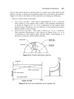
final quasi-three-dimensional flow. These surfaces are shown in Figure 8-13.
The velocity distribution in the meridional plane varies between the hub and
shroud as shown in Figure 8-14. The velocity distribution between the suction
and pressure surfaces also varies. The velocity between the suction and pres-
sure surfaces varies because the blades are working on the fluid and, as a result,
there must be a pressure difference across the blade. The form of velocity
distribution on the rotor blades at the hub and shroud and also between the
pressure and suction sides is shown in Figure 8-15.
The boundary layer along the blade surfaces must be well energized so
that no separation of the flow occurs. Figure 8-16 shows a schematic of the
flow in a radial-inflow impeller. Off-design work indicates that radial-inflow
turbine efficiency is not affected by changes in flow and pressure ratio to the
extent of an axial-flow turbine.
In a radial-inflow turbine the problems of erosion and exducer blade
vibration are prominent. The size of the particles being entrained decreases
with the square root of the turbine wheel diameter. Inlet filtration is sug-
gested for expanders in the petrochemical industry. The filter usually has to
Figure 8-13. The two major flow planes in a radial-inflow turbine.
Radial-Inflow Turbines 333
//SYS21///INTEGRA/B&H/GTE/FINAL (26-10-01)/CHAPTER 8.3D ± 334 ± [319±336/18] 29.10.2001 4:01PM
Figure 8-14. Meridional velocity distribution from hub to shroud along the blade
length.
Figure 8-15. Relative velocity distribution of suction and pressure side along the
blade length.
334 Gas Turbine Engineering Handbook
//SYS21///INTEGRA/B&H/GTE/FINAL (26-10-01)/CHAPTER 8.3D ± 335 ± [319±336/18] 29.10.2001 4:01PM
be an inertia type to remove most of the larger particles. The exducer fatigue
problem is serious in a radial turbine, although it varies with blade loading.
The exducer should be designed so that it has a natural frequency four times
above the blade passing frequency.
Noise problems in a radial-inflow turbine come from four sources:
1. Pressure fluctuations
2. Turbulence in boundary layers
3. Rotor wakes
4. External noise
Severe noise can be generated by pressure fluctuations. This noise is created
by the passage of the rotor blades through the varying velocity fields produced
by the nozzles. The noise generated by turbulent flow in boundary layers
occurs on most internal surfaces. However, this noise source is negligible.
Noise generated from rotor flow is due to the wakes generated downstream in
the diffuser. The noise generated by the rotor exducer is considerable. The
noise consists of high-frequency components and is proportional to the eighth
power of the relative velocity between the wake and the free stream. Outside
noise sources are many, but the gear box is the primary source. Intense noise
is generated by pressure fluctuations that result from tooth interactions in
gearboxes. Other noises may result from out-of-balance conditions and vibra-
tory effects on mechanical components and casings.
Figure 8-16. Boundary-layer formation in a radial-flow impeller.
Radial-Inflow Turbines 335
//SYS21///INTEGRA/B&H/GTE/FINAL (26-10-01)/CHAPTER 8.3D ± 336 ± [319±336/18] 29.10.2001 4:01PM
Bibliography
Abidat, M.I., Chen, H., Baines, N.C., and Firth, M.R., 1992. ``Design of
a Highly Loaded Mixed Flow Turbine,'' Proc. Inst. Mechanical Engineers,
Journal Power 8 Energy, 206: 95
Â
±107.
Arcoumanis, C., Martinez-Botas, R.F., Nouri, J.M., and Su, C.C., 1997. ``Per-
formance and Exit Flow Characteristics of Mixed Flow Turbines,'' Interna-
tional Journal of Rotating Machinery, 3(4): 277
Â
±293.
Baines, N.A., Hajilouy-Benisi, A., and Yeo, J.H., 1994. ``The Pulse Flow Perform-
ance and Modeling of Radial Inflow Turbines,'' IMechE, Paper No. a405/017.
Balje, O.E., ``A Contribution to the Problem of Designing Radial Turbo-
machines,'' Trans. ASME, Vol. 74, p. 451 (1952).
Benisek, E., 1998. ``Experimental and Analytical Investigation for the Flow Field
of a Turbocharger Turbine,'' IMechE, Paper No. 0554/027/98.
Benson, R.S., ``A Review of Methods for Assessing Loss Coefficients in Radial
Gas Turbines,'' International Journal of Mechanical Sciences, 12 (1970),
pp. 905
Â
±932.
Karamanis, N. Martinez-Botas, R.F., Su, C.C., ``Mixed Flow Turbines: Inlet
and Exit flow under steady and pulsating conditions,'' ASME 2000-GT-470.
Knoernschild, E.M., ``The Radial Turbine for Low Specific Speeds and Low
Velocity Factors,'' Journal of Engineering for Power, Trans ASME, Serial A,
Vol. 83, pp. 1
Â
±8 (1961).
Rodgers, C., ``Efficiency and Performance Characteristics of Radial Turbines,''
SAE Paper 660754, October, 1966.
Shepherd, D.G., Principles of Turbomachinery, New York, The Macmillan
Company, 1956.
Vavra, M.H., ``Radial Turbines,'' Pt 4., AGARD-VKI Lecture Series on Flow in
Turbines (Series No. 6), March, 1968.
Vincent, E.T., ``Theory and Design of Gas Turbines and Jet Engines,'' New
York, McGraw-Hill, 1950.
Wallace, F.J., and Pasha, S.G.A., 1972, Design, Construction and Testing of a
Mixed-Flow Turbine.
Winterbone, D.E., Nikpour, B., and Alexander, G.L., 1990, ``Measurement of
the Performance of a Radial Inflow Turbine in Conditional Steady and
Unsteady Flow,'' IMechE, Paper No. 0405/015.
336 Gas Turbine Engineering Handbook
//INTEGRA/B&H/GTE/FINAL (26-10-01)/CHAPTER 9.3D ± 337 ± [337±369/33] 29.10.2001 4:02PM
9
Axial-Flow Turbines
Axial-flow turbines are the most widely employed turbines using a compres-
sible fluid. Axial-flow turbines power most gas turbine unitsÐexcept the
smaller horsepower turbinesÐand they are more efficient than radial-inflow
turbines in most operational ranges. The axial-flow turbine is also used in steam
turbine design; however, there are some significant differences between the
axial-flow turbine design for a gas turbine and the design for a steam turbine.
Steam turbine development preceded the gas turbine by many years. Thus,
the axial-flow turbine used in gas turbines is an outgrowth of steam turbine
technology. In recent years the trend in high turbine inlet temperatures in gas
turbines has required various cooling schemes. These schemes are described
in detail in this chapter with attention to both cooling effectiveness and
aerodynamic effects. Steam turbine development has resulted in the design
of two turbine types: the impulse turbine and the reaction turbine. The
reaction turbine in most steam turbine designs has a 50% reaction level that
has been found to be very efficient. This reaction level varies considerably
in gas turbines and from hub to tip in a single-blade design.
Axial-flow turbines are now designed with a high work factor (ratio of stage
work to square of blade speed) to obtain lower fuel consumption and reduce the
noise from the turbine. Lower fuel consumption and lower noise requires the
designof higher by-passratio engines. A high by-pass ratio engine requires many
turbine stages to drive the high-flow, low-speed fan. Work is being conducted to
develop high-work, low-speed turbine stages that have high efficiencies.
Turbine Geometry
The axial-flow turbine, like its counterpart the axial-flow compressor, has
flow, which enters and leaves in the axial direction. There are two types of axial
337