Gas Burners for Forges Furnaces and kilns phần 3 ppt
Bạn đang xem bản rút gọn của tài liệu. Xem và tải ngay bản đầy đủ của tài liệu tại đây (7.44 MB, 21 trang )
Gas
Burners
3
reducer onto the burner tube and mark its high areas while the trued-up end of the
choke sleeve rests against it. Grind or file away any high spots, while frequently
reassembling the parts for comparison. Place the bell reducer on the sheet of sand-
paper to finish flattening its face.
Now, use a "z" size drill bit to enlarge the threaded hole on the reducer's small end
to hold the accelerator. Place a chair or five gallon bucket on the floor on which to
sit, clamp the locking pliers around the bell reducer just behind the large lip, and
place the reducer on the floor in front of you (the locking pliers will be set at a slight
angle). With one foot on the pliers and the drill bit resting on the reducer, position
the drill motor as near to vertical as you can while sitting leaning forward over your
work. Rest your arms on your legs. Gently enlarge the existing hole. You will be able
to feel the point where the drill bit penetrates the material's far side in time to stop
before it drills into the floor. Having your body braced in this position will give you
surprising control over the drill's aim and a good brace against kickback when the bit
reaches the far side of the existing hole.
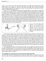
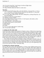
Fig.
3-4
Note the edge of the
drill bit is even with the lip's
edge, in the left side of the
drawing. So, the bit's tip will
scratch a line at the proper
place for center punching, as is
shown on the right side of the
drawing
Next, punch-mark a place in the side of the lip on the reducer's small end for a
setscrew. Use the #29 bit and the
#8
x
32 tap to thread the hole. When you look at the
drawing, notice that the setscrew is placed off-center (into the forward edge of the
bell reducer's lip). This is done to insure enough room to keep the screw away from
the lip's back edge. Also, make sure the hole is placed far enough back from the for-
ward edge so that the drill bit can run true. To do so, place the #29 drill bit on the
bell reducer so that the bit is just back from the lip's forward edge and use it for a
scribe; then punch-mark your hole over the scratch mark. Doing this will keep the
bit far enough from the edge of the lip to ensure that it doesn't run off to one side.
The larger size of the tap thread will still follow the hole even though it runs into the
curve beyond the lip.
By screwing the reducer onto the burner tube you can again use your foot to trap
the part while sitting over it in a chair. Even with a small hole, the leverage and con-
trol this method gives you is good. If you temporarily slide the nozzle back onto the
burner tube while you drill this hole, it is easier for you to keep the drill aimed at
right angles with the reducer.
5.
Installing the thumbscrew in the burner body, part
#5
The time has come to permanently mount the choke sleeve. Therefore, place the
sleeve on the 112-inch pipe, centered over the ink line with its squared end against
Building the
I
12-inch Burner
the bell reducer. The reducer should be snug but not screwed down completely tight.
Scribe a cross line in the center of the forward end of its slot for a thumbscrew hole.
Remove the bell reducer and choke sleeve. Center punch the mark, drill a pilot
hole with a 118-inch bit, and enlarge the hole with the
#3
bit (use the same control
method as before). Now, thread the hole with the
114 x 20 tap. Clean up the burrs,
inside and outside of the tube, with files. Re-thread the hole (this is called chasing the
thread). Now re-file the hole. All these steps are needed to get a smooth sliding action
on the choke.
Reassemble the choke and tighten the thumbscrew. One or two small flat wash-
ers are used with the thumbscrew to create a shoulder. This helps to more effective-
ly lock the choke. Count the number of excess threads inside the burner tube. You
must remove the excess thread. To do so, clamp the thumbscrew in the locking pli-
ers, run a 114 x 20 nut down to where you have determined your thread length should
end and grind off the excess. Afterward, unscrew the nut and file the burr off the end
of its thread. You can use the half round file's edge or the miniature flat file in the tip
cleaner set to remove this burr. Reassemble your parts, tighten the thumbscrew, and
file off any excess thread remaining inside the burner tube.
6.
Laying out the air openings, part
#2
Slide the choke sleeve all the way forward (toward the nozzle), lock the thumbscrew,
and scribe a line around the burner tube at the sleeve's back edge. Now slide the
sleeve all the way back. Screw on the bell reducer until it touches the sleeve. Use the
ink marker to make a line on the thread where it meets the lip of the bell reducer.
Remove the reducer and the choke sleeve.
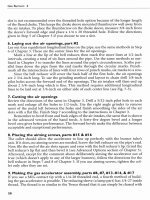
Fig.
3-5
The forward end of the
inked area as it appears with the
choke sleeve against the bell reduc-
er and the crossing line scribed for
the punch mark.
Cut a piece of paper about three inches wide and wrap it around the burner tube.
Mark the point where it overlaps itself. Draw a line on this point at a right angle; cut
off the excess paper and then flatten it out on a table. Use dividers or a tape measure
to find and mark four equal spaces, beginning on the paper edge (the edge, a mark,
a second and third mark, and finally the other edge). Mark a spot halfway between
an edge and the first line on the paper. This spot will be centered over your scribed
and inked line on the pipe. Mark the four places. They will become the centerlines of
your air openings. Replace the paper around the pipe and transfer your marks. Check
to make sure the spaces are equal and then scribe the other four lines.
The ink line represents one of the four ribs that will be left between the air open-
ings. It is the only important rib because the slot in the choke sleeve slides over it.
Gas
Burners
3
Therefore, it is necessary to keep this one rib wider than the width of the slot so that
the burner can be sealed if it is used in a forge. It isn't as important if the other ribs
or the air openings between them end up imperfectly proportioned.
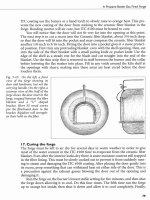
Fig.
3-6
Centers for the air openings are laid out on a
paper template. It is cut about
1 1/2-inches wide. Line
"b"
is about 2 5/8-inches long. The three "a" lines divide the
paper into four equal spaces. They should end up about
13/16-inches apart.
The
short line is the centering line,
and is placed over the scribed line of the inked area, which
marks the choke sleeve's rib. The paper's two edges come
together, forming the fourth line.
The other four scribed lines now get cross lines marked at 114-inch intervals all
the way from the first scribed crossing line to the inked line next to the bell reducer's
lip. You will need to start by grinding a parallel groove in the thread. It should be
deep enough to allow center punching. Afterward, reestablish the scribed line
through this area, on all four of the parallel lines for the air openings. Remember to
leave the inked line for the choke sleeve rib alone.
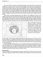
Fig.
3-7
Shows the cross marks every 1/4-inch. Note the bare area in the center of the pipe where
the threading has been ground flat and scribed again. Be sure to
fle off the burrs created by the
grinding before screwing the bell reducer back onto the thread.
After scribing the threaded area of the four parallel lines, measure and scribe
crossing lines every 114-inch. Replace the choke and use it to transfer the crossing
lines from the layout on the first line to the other three. Remove the choke and
punch-mark all the crossing lines (including the first scribed line and the inked line).
7.
Making the air openings, part
#2
Drill a 118-inch pilot hole in each mark. You can put your foot on the burner tube to
trap it on the floor for drilling from your chair. However, stand up in order to put
greater weight on the part before enlarging all the holes to 5116-inch. If you have had
trouble keeping your punch-marks in a straight line, drill 114-inch holes and file
them out to 5116-inch afterward. Clamp the part securely to a table or in a vice and
use the thin blade in the grinder to begin turning the rows of holes into slots
Building the
I
12-inch
Burner
(remember not to get over ambitious with it), or use the rat-tail or round file
between the holes. Finish smoothing the sides of the air openings with a flat file.
The ribs, which remain between the slots, will not withstand physical abuse. Even
the stress of screwing the bell reducer back into position could bend the tube out of
alignment. Always use a bar, pushed through the slots like a spanner wrench, to hold
the burner tube. It should be as close as possible to the threaded end. Take out the
"spanner wrench" to unscrew the reducer on later.
Screw the bell reducer snugly into the pipe and file the back end of the air open-
ings even with it. Remove all burrs from the slots. The placement of the choke cov-
ers the round forward ends of the slots, and with the back ends filed square, the slots
effectively become rectangles. The importance of the rectangular configuration,
rather than slots can't be overstated.
8.
Placing the aiming screws, part
#I
5
The accelerator in this burner can be aimed. If you drilled the size
"Z"
hole perfectly
true to the burner's axis, you still need to change the aim of the accelerator to get the
best flame characteristics at different gas pressures. To install the aiming screws, drill
four #29 holes and tap them for
#8
x 32 thread. Space them equally around the bell
reducer's side and as far back from the lip of the large end as you can get without
encountering the curve of the bell shape. This allows the setscrews to clear the
threaded end of the pipe. You can use the air slots on the burner tube for an approx-
imate positioning and then refine the hole placement with the dividers or a tape
measure. Drill and thread these holes and place the longer setscrews in them. This
allows you to aim the accelerator perfectly.
Fig.
3-8
Four of the locking set screws (part
#16)
are shown in the smaller lip), and three of
the four aiming set screws (part
#15)
are shown
just below the curve in the bell shape. Note the
way they trap the accelerator's gas tube. By
moving them a small amount, the tip of the
accelerator can be aimed anywhere within the
interior of the burner body.
While drilling through the bell reducer you may encounter something unexpect-
edly hard near the place where you thought to finish the hole, which is the steel pipe
thread. Sometimes a pipe thread runs undersize because the dies in the threading
machine weren't set quite right. This will allow the pipe to thread further into the
female fitting then it was designed to do and thus into the area where you are drilling
the holes for your aiming screws. Simply stop drilling, unscrew the burner tube, and
power sand the 112-inch pipe thread back to where it doesn't encounter your hole.
Then use the flat file to remove the burr from the thread end and screw the parts back
together. Don't try running the threaded holes through the pipe. Even if you succeed,
your fit-up would become a nightmare afterward.
Gas Burners
3
9.
Making the temporary accelerator, parts
#6,
#
1
3,
#
1
4,
and
#I
7
By building this accelerator, the hand burner can be used to finish its own construc-
tion, ending the need to buy a commercial propane torch and MAPP gas bottle. Also,
since the hand burner will put out considerable heat (even with the temporary accel-
erator installed), high temperature silver braze can be easily used. The extra brass
3116-inch inverted female nut and 4-inch pipe nipple can be recycled into an accel-
erator for the next burner after the first accelerator is completed.
The length of the brass nuts insures that the hole and its thread will have a good
chance of running true. The length of the nut also promotes accuracy when the parts
are brazed together. It is important to have the contact tip installed in line with the
accelerator pipe, because bending the part into position afterwards isn't desirable
when its threads must be able to seal.
Begin by screwing the 118-inch x 1-inch pipe nipple into the 118-inch brass cou-
pling to make a drill jig. Next, screw one of the two 3116-inch inverted female nuts
into the coupling's other end and drill a hole through the nut with the parts held in
a vice or in locking pliers.
Fig.
3-9
Numbered parts for drilling with the fixture.
Use a
#7
drill bit for the hole and run it into the nut from the far end of the 1-
inch nipple. This further ensures an axially true hole. Remove the nut and repeat this
process with the second nut. Now use the 114-inch x 28 tap and run it though the
nipple to thread the nut. Do not use tapping fluid (because that would interfere with
soldering later). You must either screw the nut very tightly unto the coupling or
clamp the locking pliers gently unto it instead of the coupling to hold the
fmture for
drilling and tapping. Otherwise the nut will tend to unscrew itself during the work.
Remember to only turn the tap between an eighth and a quarter-revolution at a
time. After each forward twist, reverse the motion enough to break off the burr.
Gently tapping the hole this way, and completely backing the tap out if it starts to feel
like it's binding, will guard against breaking it off in the dry thread. You may have to
use a bottoming tap to complete the threading of this part.
Blow the metal shavings out of the nut and remove it. Place Teflon tape on the
other nut, insert it in the coupling, and repeat this process. Leave the second nut in
the coupling. Place the nipple into the drill motor. Spin the whole assembly under a
file or hand grinder to reduce the coupling's diameter until it will fit easily into the
Building
the
I
12-inch Burner
112-inch burner tube. Remove the 1-inch pipe nipple. Blow the metal shavings out of
the nut and coupling.
Use a 4-inch brass pipe nipple, instead of steel, for the accelerator's gas tube
because it has closer tolerances, but it still may not fit easily into the bell reducer's
hole. If it doesn't, spin it in the drill motor using sandpaper. Keep checking for a slid-
ing fit as you sand the part. Once the nipple fits into the bell reducer, wrap Teflon
tape on its thread and screw it into the coupling. Place Teflon tape on the threads of
the Tweco contact tip and screw it into the 3116-inch inverted nut.
It is necessary to use a sealant on all the pipe threads, even though this is a tem-
porary part. The slightest gas leak will catch fire. On the contact tip this would desta-
bilize the flame, and anywhere else on the burner the gas will ignite in a startling way.
This will cause you to flinch, and flinching when you are aiming the torch is never a
good idea.
Fig.
3-10
This drawing illustrates how the temporary accelerator tightlyfits inside the burner
(shown in outline) even after it is ground down
When the temporary accelerator is ready, unscrew the bell reducer and place the
accelerator inside of it, with the contact tip placed as far back as the coupling per-
mits. Screw the reducer onto the burner tube and barely tighten the locking screw. At
this point, reinstall the burner nozzle.
The next steps of assembly use the process of brazing. For complete instructions
and to better understand this technique go to Chapter 12, "Brazing".
I
0.Assembling the valve and hose fittings, parts
#8,
#9,
#I 0, #I
I,
&
#I
2
Screw the ball valve onto the accelerator. Screw the street ell into the back of the valve
and the 1-inch nipple into the ell. Screw the 118-inch
x
114-inch bell reducer onto the
nipple and the outlet bushing into the reducer. Use gas rated Teflon tape or sealant
making sure to keep it away from the last two threads on the parts. The torch should
now be ready to use.
So, try it out! Open the choke about a 114-inch, then set your regulator pressure
to 4 PSI and ignite the hand torch. Open the choke all the way, and slowly increase
the gas pressure. Because of turbulence caused by the temporary accelerator's cou-
pling, you will experience barely acceptable performance, but it will still be more
than hot enough to silver braze. On the other hand, because of the low performance,
Gas Burners
3
tuning isn't difficult yet. Play with the burner for a few minutes to become familiar
with its performance.
I
I.
Building the permanent accelerator, parts
#6,
#7,
and #I
3
A
pocket for the inverted nut is created in the 3-inch pipe nipple by drilling it out
with an N size bit to a depth of about 112-inch beyond the thread. To do this, screw
the other 118-inch coupling onto the 3-inch pipe nipple, and gently clamp the lock-
ing pliers onto the nipple. Clamp the part on the thread just beyond the coupling.
Then screw the 1-inch nipple into the coupling's other end. Gently drill through the
1-inch nipple. When you feel the drill go through the 1-inch nipple's far end, stop
drilling, and push the drill bit forward by hand until you feel it touch the end of the
3-inch pipe nipple. Mark the drill bit's depth and then add 314-inch. Make a second
mark and continue drilling until the second mark reaches the coupling. Unscrew the
3-inch pipe nipple, and cut off the threaded portion of its end. Save the drilling jig
for the second accelerator.
Fig.
3-1 1
The left side is the drilled out 1/8-inch pipe nipple, still screwed into the fixture. On
the right, the thread has been cut
awayfiom thefinished pocket.
Now the outside of the inverted female nut is turned down to fit within the
"pocket" made for it in the end of the brass pipe nipple. Screw the second contact tip
into the other inverted female nut, and then use it to hold the part in the chuck of a
hand drill. Spin the part in the drill while holding a flat file against the fitting's
Fig.
3-12
The
MIG
tip is screwed into the nut on the left side of the drawing. The middle is the
turned down nut which is ready to be inserted into thepocket in
thegas pipe, shown on the right.
The dark lines inside the pipe end represent the pocket.
42
Building
the
I 12-inch Burner
threads. If your nut becomes loose, file on the other side of the part. Keep checking
for fit in the pipe pocket until you have a snug fit. Use the "tooth brush to clean the
shoulder of the nut. Use pliers on the shoulder to unscrew it from the copper tip
before releasing them from the drill chuck.
Flux the turned section of the brass fitting (outside only), making sure to keep
the flux away from the end of the part. Insert the part into the brass pipe. If you need
to press the parts together, remember to screw the other end of the pipe nipple into
the 318-inch x 118-inch bell reducer first to protect its threaded end, and then gently
tap the parts together.
Now silver braze the parts together. It is best to do this in the upright position,
with the nipple temporarily screwed into the 118-inch x 114-inch bell reducer (smear
oil on these threads). The bushing can then be held in a vice or the locking pliers.
After brazing, the part is chucked in the drill and spun under the file to remove any
excess braze from the exterior of the pipe and to round off the fitting? hex faces.
Then run the 114-inch x 28 tap into the fitting to chase (clean up) the threads.
Fig.
3-13
Accelerator parts are silver brazed with
a reducing flame. The primary flame is jagged
and greenish tinged with almost no rear cone.
The secondary flame is allowed to wrap around
the heating parts, keeping oxygen away
fiom
them. The brazing rod is on the opposite side
from the flame, which helps to draw the liquid
metal completely around the joint as it flows
toward the heat source. At this point,
theflux has
mostly bubbled away leaving only a thin coating
of "glass" on the metal surfaces.
After removing the pipe from the drill, clean the flux out of it with a small drill
bit (run with the drill motor reversed so it won't damage the inverted nut) or scrape
with a round file. Blow any metal shavings out of the accelerator. Use Teflon tape to
ensure a good seal and screw the contact tip into the accelerator pipe (keeping the
tape away from the thread end). Performance of the torch will be increased if you
bevel the shoulder formed between the contact tip and the larger diameter pipe.
Replace the temporary accelerator with the permanent one then recycle the spare
parts into a second finished accelerator. When you drill the 4-inch pipe nipple, mark
it the same as the three-inch nipple. The extra inch of length will be useful in the
314-
inch forge burner. Screw the first 118-inch x 1-inch pipe nipple into the other cou-
pling and keep them both for tooling.
Tighten only the locking screw enough to keep the accelerator from moving
while you test its position during tuning. Once you're satisfied with the position
tighten further. Even with its face smoothed, the setscrew will tend to create a dim-
ple in the brass pipe when fully tightened.
Gas Burners
3
To check the accelerator's aim, turn the burner and view the tip through each of
the air slots. Then hold the burner up to a light and look at the tip through the burn-
er nozzle.
Aim the accelerator assembly by manipulating the forward ring of setscrews until
the contact tip is axially true with it. Now tighten the four aiming screws to just snug.
Tighten when tuning is complete.
12.Tuning
Tune burners in the open air. To see the flame, tune the burner in a shaded area;
bright daylight can make the flame nearly invisible. Burners are more easily observed
this way. The interior environment of the forge can not aid their combustion, so they
will run better if placed the forge afterward.
Begin by placing the flare (see Step 14) at 1-inch of over-hang beyond the burn-
er tube's end. Next run the burner at various settings while moving the flare back
toward the burner tube's end (effectively shortening the flare stick-out) to find it's
best setting and to familiarize yourself with it. This burner should run best at 1-inch
of overhang. The accelerator is likewise moved back and forth to find it's optimal set-
ting. It should run best if set with its tip about 114-inch back of the fully open choke.
Start the burner with the choke about 114-inch open and the regulator set at
5
PSI. After about a minute the choke can be opened more. After two or three minutes,
the choke can be run wide open. The choke should be fully open while tuning the
burner and only afterward used to fine-tune the flame characteristics for different
pressure settings or for making a reducing flame during special applications.
This model has an adjustable aim for the accelerator. The flame characteristics
can change drastically on this burner (especially at low pressures) long before a
miss-
shaped flame alerts you to a poorly aimed accelerator, so you must consider aiming
to be one of the steps to tuning this particular burner. In the smaller diameter burn-
ers like this one, the best performance isn't always obtained by aiming the accelera-
tor perfectly true. At some pressures you will want to aim the burner a slight angle
for maximum performance. This can be understood with practice.
A greenish tinged flame is a reducing flame. This is several hundred degrees cold-
er than a neutral flame, and because the gas isn't being completely burned, it is pol-
luting. However, it can be useful to run a slightly reducing flame for short periods in
order to help prevent oxidation of surfaces being brazed.
Tune the flame leaner and the inner cone becomes clear. The flame front is now
a pale blue. This is the beginning of a neutral flame.
Now transfer your attention to the secondary flame. Tune a little leaner and the
secondary flame reduces. With the advanced burner it almost disappears producing
a high-end neutral flame that is as hot as a flame can be tuned with gas. You can make
flames larger, but not anymore efficient. Flame shape will change according to gas
pressure and the position of the accelerator, but the roughened wave front and blunt-
ed end (like the tip of a baseball bat) is typical for the advanced burners.
As the burner is tuned still leaner, the flame becomes a darker blue. This is the
beginning of an oxidizing flame. It will tend to burn your work and is not as hot as
Building the
I
12-inch
Burner
the neutral flame. It will also produce carbon monoxide (although to a lesser degree
than a reducing flame).
The flame is tuned by moving the choke for different pressure settings. After the
nozzle heats up, this burner tends to run well, but you can still fine-tune it with the
choke. Before the nozzle heats up it is easy to open the choke too far and create an
oxidizing flame. Please note that if you include the advanced options, tuning charac-
teristics will change drastically. The burner will no longer be as forgiving and will not
tend to run in a balanced fashion by itself. You will have to pay close attention to
choke position when you change pressure settings on the advanced burner. Don't be
concerned about not being able to run the choke wide open at most pressure settings
with the flared choke. It simply scoops up more air than it can use at higher pressures
(unless it is used in a forge or furnace).
Fig.
3-14.
A
typical high-end neutral
flame emerges from an orange hot noz-
zle; there can even be an orange enve-
lope until the nozzle heats up. It is dis-
tinguished by a clear cone behind the
jagged light blueflame. The jagged look
comes from minor explosions ripping
back and forth along the flame's wave
Front.
A
wisp of secondary flame and
yellowish-orange flames winking out
almost instantly is customary with the
smaller burners.
Now see how far down you can run the pressure. After a few tries, you will note
that below a certain minimum pressure range the burner's flame becomes feeble. All
the jet ejector burners have a threshold pressure below, which they act like induced
burners. What is important to understand about the threshold pressure is that the
burners are not nearly as stable below it as they are above it. If you are using a single
stage regulator, your system pressure will tend to fluctuate occasionally, and if you are
running the burner below its threshold pressure it will falter. So, when you place the
burner within a forge or furnace, remember to keep the idler adjustment above this
minimum pressure (see Forge Idler section of Chapter
5).
The expansion of the heated nozzle is greater than the expansion of the air-
cooled burner body. Inside a forge the difference is great enough to loosen the noz-
zle and allow it to slide off the end of the burner unless you severely over tighten the
nozzle's setscrews. This is likely to damage them where they must be drilled out to
change the worn out nozzle. Pinning the nozzle to the burner with an additional
screw through all three parts is advised if you will be using the torch to power a
Mini-
forge or small furnace. Wait until you are thoroughly familiar with the finished burn-
er to do this. Don't allow any protruding thread inside of the nozzle. If you are only
going to use the burner as a hand torch, then snug the setscrews in the nozzle posi-
tion that best suits performance and retighten them with the nozzle fully heated. To
remove the nozzle, heat it up; this will relieve the pressure on the setscrews.
Gas
Burners
3
13.Advanced burner options
The burner you have just made is powerful and very forgiving in its performance
characteristics. It can be made more powerful with some modifications the first of is
to grind the excess lip on the large end of the bell housing down even with the rest
of its body. Use the flap disk and revolve the burner under it by hand. Afterward, light
the burner and note the increased performance.
It is a good idea to use a second bell reducer for the changes so that you can
switch back and forth between the two parts, thus maintaining a wide range of burn-
er performance. This also allows you greater accuracy and stability when spinning
the parts as shown in Fig. 3-16.
Fig.
3-15
Shows the second bell reducer with its lip flattened by hand grinding on the left side.
The right side shows it with bevel, ground by spinning it while mounted on part
#
17.
Next mount it on a spare pipe or use a second bell reducer (recommended).
Remove the accelerator assembly and unscrew the reducer on the drill fixture assem-
bly. Place them in the drill motor and revolve them under an angle grinder. Use the
setscrews to adjust it until it no longer wobbles, then sand a bevel in the forward edge
of the bell reducer where you just removed the excess lip. Both the removal of the
"lip" from the bell reducer and the grinding of a bevel in that area help to increase
airflow by streamlining the burner at the rear of the air intakes. Reassemble the burn-
er and tune it again. You will notice that with each increase in performance, the burn-
er becomes less forgiving about choke placement, which is natural.
Finally, build the flared choke sleeve and install it on the burner. You will notice
another jump in performance and in touchiness. Also, the burner can once again be
easily sealed at shutdown when used in a forge or furnace.
14.
Forging a flare on the choke sleeve
This choke has a flared end. You can forge the flare shape on the end of 314-inch gal-
vanized pipe or metal tubing.
If you use galvanized pipe, you must first heat it up enough to burn away sever-
al inches of coating before performing the forge work. This is done in order to avoid
breathing the fumes from the burning zinc. Place a two-foot section of 314-inch pipe
in a charcoal or wood fire (outside) and stay away from the fumes as the zinc burns
off (although pipe is called galvanized, most pipe is actually zinc plated). Afterward,
Building the
I
12-inch Burner
Fig.
3-16
Advanced burner drawing. The fabrication instructions for part
#19
are given in
Chapter
4,
step
4.
Gas Burners
3
brush and file any remaining plating from the pipe. Remember to thoroughly clean
the inside also. Do not use black pipe for the choke. It can be much harder to get a
sliding fit with.
Clamp a 112-inch or 518-inch round bar in the vice. File a mark on the top of the
bar at 314-inch. Heat a short area of the tube's end and place it over the round bar,
up to the mark. You can use a barbecue for heating if you haven't made the basic
burner already. With a light hammer, tap the pipe on its side while revolving it on the
bar. Try to create a flare about 118-inch to 3116-inch larger diameter than the rest of
the pipe.
Be
careful when quenching the heated pipe, as it will instantly turn water into
steam with a danger of burning you with a blast shot out of the pipe. You should let
the pipe air-cool if you're unfamiliar with this process. If you are in a hurry and no
one else is around, cool the hot end of the pipe into a slack tub and aim the other end
away from the area.
A
hot blast of steam will shoot out.
A
taper to the cross section of the metal wall will tend to form, making the flare
thinner at its edge. This is fine. Cut the flared tube off at 3 112-inch that will become
the choke sleeve.
Fig.
3-17
At left, the choke sleeve has a slot. In the cutaway view on the right a thumbscrew is mounted
in a threaded hole, andpressing against the burner tube wall, which is shown in cutaway. The bell reduc-
er is shown cutaway, exposing the squared back of the air opening. Its forward end's bevel is shown in
X-
ray view. See Fig.
4-5
for comparison.
Mount the flared part, sitting vertically in a vice. File the lip of the flare even.
Mount a grinding stone in the drill motor. Then move the part to a convenient angle
and start grinding the inside of the flare reasonably smooth, ending with a rounded
lip. Turn the part and grind out the whole inside of the flare, section by section.
Remember it doesn't have to be perfect.
Use the small angle to mark a straight line on the cylindrical portion of the sleeve.
Make sure the line is over the weld seam in order to reduce your file work. Measure
318-inch from the straight end and center punch. Continue marking and center
punching at intervals of 114-inch along the cylindrical portion of the tube, stopping
Buildine the
I
R-inch Burner
114-inch from the beginning of the flared area. Drill 118-inch pilot holes and enlarge
the holes toll4-inch. Grind and file into a smooth sided slot. File the remaining areas
of the interior weld seam flat.
The flared choke is employed to best advantage on burners that are used in forges
and furnaces or when used with oversized nozzles. In other words, the flared choke
is best used when maximum draw on the burner is more important than fine-tun-
ing. Therefore, mounting the thumbscrew 318-inch from the forward end of the
choke sleeve is recommended over using a slot because this option will allow the
choke to fully open and close without extending the length of the choke sleeve (the
flared section reduces the slot length).
A
longer choke sleeve would limit the depth
that this burner can be placed within a forge or furnace too much.
The accelerator is positioned with its tip just beyond the bevel at the front of the
air openings when using a flared choke sleeve. Temporarily remove the thumbscrew
and slide the choke all the way forward to clear the intake area, then place and lock
the accelerator in position. This puts the accelerator forward of the choke sleeve, even
when it's in the full open position.
1
5.
Advanced accelerator assembly
The accelerator assembly shown below is simpler to fabricate and easier to find parts
for than any of the others. It is also shorter and powerful enough to allow the ball
valve to be placed out of alignment for handwork, thus shortening the torch.
A
fur-
ther advantage is its ability to bend. This ends the necessity for aiming screws in the
bell reducer.
Fig.3-18
A
cross section of the advanced accelerator. On the left is the cutof1/8-inch pipe nipple. Its
forward end is beveled to increase airflow. The dark part in the center is refrigeration tube. It and the
outer pipe have been beveled to increase gas
pow.
On the right is a tapered MIG tip with filed of
thread, allowing it to fit within the copper tube.
However, brazing it requires a higher skill level than the other accelerators, and it
is not as easily cleaned for maintenance. If the contact tip orifice is damaged in any
way (for instance by being dropped), this accelerator might as well be thrown away.
It is best used in smaller diameter burners like the hand torch.
Parts
list
(4) 118 NPT
x
112 NPT bell reducer
(6) 118-inch brass pipe nipple three inches or longer
(7)
1 112-inch long standard or tapered MIG contact tip for .023 or 6mm wire.
(18) About one foot of 114-inch copper refrigeration tubing
Gas
Burners
3
Tool
list:
(A)
Small pipe cutting tool
(B) 118 NPT die (recommended)
(C) Set of extra long torch tip cleaners (recommended)
(D) 3116-inch or smaller round file (recommended)
(E)
Pipe cleaners (recommended)
1
6. Fabrication, parts #6,
#7,
and
#
1
8
Begin by using a tightly rolled cylinder of sandpaper or a nail with sandpaper
wrapped around it to clean the oxide film from the inside of one end of the 118-inch
pipe nipple (the file isn't any good for this). Try for a depth of about 2-inches. Next,
use the pipe cutter to detach a 1 112-inch long section from the sanded end. Do not
saw the part. The deformation of the nipple and the internal burr left by the pipe cut-
ter are essential to your construction plan.
Chuck the pipe and spin it under a file to form a partial bevel on the outside of
the cut end. Now use the pipe cutter to separate a 2 112-inch long piece of the 114-
inch refrigeration tubing. Choose a reasonably straight section of the tubing, but
don't worry about whether it is perfectly true or not. Clean out the internal burr and
sand the oxide film from one end of the
114" tube to a depth of 112-inch. Then sand
the complete outside length of the tube to prepare it for brazing.
Fig.
3-1
9
The blade of the pipe
cutter deforming the tubing at
the point of separation, making
a narrowed end in which to
trap the
refiigeration tubing.
On the right,
a
file is forming
the bevel needed for good air-
flow.
Next place the tubing on a hard surface and insert the end of a small drill bit
about 112-inch into the refrigeration tube. Tap lightly on the last 114-inch of the cop-
per tubing while revolving it around the hardened shank of the drill bit. The tubing
will expand under the hammering to form a misshapen flare.
Chuck the contact tip in your drill and revolve it under a file until its threaded
end slips into the refrigeration tube, then sand its shoulder area near the planned
joint. If you use a standard tip, reverse its position in the drill chuck and spin it under
a file to taper the forward end before inserting it in the refrigeration tube. Remember
to leave some material surrounding the tip's orifice (as shown in previous drawings).
Use the 3/16" round file or a nail with sandpaper wrapped around it to carefully
enlarge the burr in the 118" pipe until the copper tube will just barely slip through it.
Then clean and flux the outside of the tube, and insert it into the 118-inch pipe,
through the threaded end as far as the tubing's flare allows. Place the two parts on a
table and use another piece of 118-inch pipe to gently force the outer pipe down the
Building
the
112-inch Burner
Fig.
3-20
The
refrigeration
tube and
threaded section of pipe. The excess pro-
trudingpast the thread of the pipe can be
sanded away after brazing. At the other
end, the tube protrudes beyond the filed
out burr left by the pipe cutting tool.
rest of the way over the flared end. If you have no extra 118-inch pipe long enough
for this, gently place a set of pliers on the tubing over the end of the outer pipe and
tap down on the pliers to force the parts together.
Thoroughly clean off any flux on the thread and wipe a little oil (any kind-even
salad oil) on the threaded end. This will burn to carbon, protecting the thread from
being silver-brazed. Wash and dry your hands before handling the parts.
Holding the parts trapped with one hand, insert the drill bit's shank about 3116-
inch into the flared end of the tubing leaning the bit at an angle, and moving it in a
circular motion, reshaping the irregular flare. This will make a better seal for the
braze.
With clean hands, flux the contact tip, keeping the flux away from its end. Push
it slowly into the 114-inch tube with a twisting motion (as though it were a threaded
part). Revolve the two parts under your finger, smearing the excess flux around the
joint. Smear a little flux around the outside of the joint where the refrigeration tube
extends beyond the 118-inch pipe.
Fig.
3-21
An oiled metal strip clamped in
lockingpliers beinggiven a thin coat of carbon
by the black wisps of almost pure carbon from
the feeble yellowflame of a fully choked burn-
er (running with a temporary accelerator
installed). The oil on the metal surface also
burns down to carbon. "Carbon blacking'' a
part or supporting surface will protect it from
being accidentally brazed.
Read Chapter 12 "Brazing." Then place the parts on built up sections of carbon-
blackened metal for brazing in the horizontal position. Or, place them on a piece of
carbon-blackened metal and held with locking pliers for brazing, in the vertical posi-
tion. Although the parts are a tight fit at room temperature, you need something to
keep the tube from falling through the pipe bottom after the pipe expands from heat-
ing in the vertical position. Pass the torch flame back and forth over all three parts
until they are a bright red, but not orange (use a reducing flame). Heat the parts from
both sides, but do not move them. Once you reach red heat, begin brazing with the
contact tip, then move on to the larger joint. Avoid drawing the braze to the thread-
ed end of the
118" pipe.
Gas Burners
3
Fig. 3-22 The accelerator
parts resting on carbon black-
ened surfaces. The illustration
also shows the same parts
clamped in the jaws of locking
pliers and sitting atop of a
carbon-blacked
flat bar.
Either method will protect the
partsfiom being brazed to the
supporting surface.
If you have a die, clean and chase the thread after the accelerator cools. You can
lightly clamp the die in locking pliers. Gently run the torch tip cleaner into the accel-
erator orifice (once only). If you have a counter sink, use it to form a bevel inside the
accelerator's threaded end (or use a drill bit run backwards). Be careful to stop short
of the exterior thread. Now deburr the bevel where it meets the orifice with sandpa-
per (not the file) and clean any
flux
out of the accelerator's interior. Then use a pipe
cleaner to remove any metal particles.
Refrigeration tubing is easily bent. There is over an inch of tubing between the
contact tip and the brass pipe. This section can be gently bent in order to straighten
the accelerator, after brazing. The accelerator can also be bent into position within
the burner
afterward.
This accelerator allows the ball valve to become part of the handle when the
burner is used as a hand torch, but a little extra power can always be added to the
burner by placing the 90-degree elbow after the valve allowing the valve to become
part of the accelerator. One position shortens the torch, while the other gives maxi-
mum power.
The long torch tip cleaners allow you to clean the orifice from the backside of the
accelerator, which is recommended if it becomes clogged from particles entering its
orifice (this can happen during improper shutdowns of a forge and from oxides pop-
ping off metals when the burner is used as a torch). If the accelerator gradually
becomes clogged from waxy buildup (due to fuel impurities), unscrew the accelera-
tor and use the tip cleaner from the front side, gently tapping the accelerator's thread-
ed end on a wooden surface.
Maintenance
Once a burner is properly tuned, it is mostly trouble free. There are four factors
worth mentioning however:
First, the accelerator orifice must be cleaned out occasionally with torch tip
cleaners. Because propane gas can leave tarry buildup inside of the orifice at the
shoulder where the larger pipe abruptly narrows at the back of the contact tip. Also,
Building
the
I
12-inch Burner
any
flux
or metal filings left from the accelerator's construction will eventually col-
lect here. If the burner's performance suddenly falls off, a partial plug in the tip's ori-
fice is the probable cause. When using the tip cleaners, you must remember that they
are essentially files and that copper is soft. Remove the accelerator from the burner
to clean it. Push the proper size wire into the contact tip once and after withdrawing
it, gently tap the bottom of the accelerator against a level surface to allow the obstruc-
tion to fall out of it. Do not use the tip cleaner as a file or you will degrade the ori-
fice.
Second, the choke should be closed completely at shutdown when the burner is
used in a forge. This is done in order to prevent unwanted heating from chimney
effects. After shutdown, buoyancy causes the heated gasses to back up through the
burner because it is no longer creating a positive force. Improper shutdowns can also
promote plugging of the very small tip orifice.
Third, the burner nozzle must be protected from overheating. It should sit at least
an inch inside of the refractory opening when used in a forge or furnace; to shelter it
from the main heated area of the forge's interior.
Finally, if this or any of the inductor burners described in this book are run at top
dead center (vertical position and facing straight down) they will run erratically and
can be snuffed out. This is not a malfunction. The spent gasses rising past their air
intakes will affect them adversely. Simply move them back to an angle sufficient to
allow the hot gasses a clear exit path when they are used as torches. Make sure the
burner collar is sealed when they are positioned at
TDC
in a forge.
Building the 314-inch Forge Burner
A 314-inch jet ejector burner is used to power the portable forge in Chapter 5. It has
the same high flame temperature and fuel saving characteristics as the 112-inch
burner, but with a greater output. A ball valve and its fittings are listed among its
parts, and they will be used for testing the burner. Afterward, they can be recycled
into fittings for the forge.
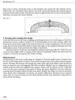
Fig.
4-1 Detail
of
the
3/4-inch
forge
burner
The major difference between the 112-in and the 314-inch burners is size and part
#
4. You will be referred back to Chapter 3 instructions for many of the steps in its
fabrication, since most of the drawings in Chapter 3 will be helpful in constructing
this burner.
If you can find a 118 x 314 NPT bell reducer, it can be employed in a similar fash-
ion to the hand torch's bell reducer. Since they are seldom found in stock, a more
common part is shown in its place. This bell reducer employs a reducing bushing
which is used as a self-tightening collet instead of the locking set screw that was pre-
viously shown. Fig. 4-
1
shows the bell reducer and collet in action. You can also refer
back to Fig. 3-15, parts
#
4B and
#19,
which show this as an alternative fitting on the
hand burner.
The gas accelerator assembly is made from a completely different plan from any
of the three designs given for the previous burner. Each burner shown will feature a
separate accelerator. Except for the
MIG
tip orifice sizes, all of these gas accelerators
are meant to be interchangeable.
Fabrication steps
#6
and
#7
show the same kind of drilling technique for making
the air intakes as used in Chapter 3. However, if you secure the burner tube at a com-
fortable height these larger openings can be made by chain drilling the air intake
Gas
Burners
4
ends and making the two longitudinal cuts just inside of scribed lines with a cutoff
wheel mounted on a 4 112-inch angle grinder. Using this procedure avoids the need
for the larger electric hand drill and 112-inch drill bit called for in the special tool list;
however, you must lay out and scribe the desired rectangular openings using the four
equidistant line centers.
Materials List:
(1A) 1 114-inch ID #316 SS tube 2 1M-inch long, ID 1.260" typical, .95" wall
(1B) 1-inch sc.
#
40 galvanized pipe or sc.
#
20 black wall pipe, 1-inch long
(2) 314-inch
#
40 black wall pipe nipple twelve inch long
(3) 1-inch
x
24-inch long galvanized steel pipe
3
(4) 314 NPT x 114 NPT bell reducer
(5)
114-20 thumbscrew and 114-inch flat washer
(6) 118-inch brass pipe nipple 4-inches long
(7)
.030-inch and .035 MIG welding contact tips 1112-inch long
5
(8) 114 NPT gas rated ball valve
(9) 114 x 90" street ell (or
90" elbow and a second short nipple)
(10) 114 NPT short nipple (preferably hex)
(1 1) 118 NPT x
114 NPT bell reducer (or threaded bushing and 114 NPT coupling)
(12)
9116-18
LH
thread to 114 MPT Outlet Bushing or 318 flared fitting
(13) 1/4-27
F
x 118 M reducing sleeve
(14) 118 NPT brass coupling
(15) Four
#8 x 32 x 112-inch SS set screws
(16) Four
#8 x 32
X
114-inch SS set screws
(17) 118-inch
X
1-inch long brass pipe nipple
(18) 118 NPT x 114 NPT steel or brass bushing
(19) One sheet of
#I20 sand paper
(20) Silver braze and flux
Note: Parts #14 and
#17 are for the drilling and threading furture. If you keep the
fucture from the hand torch, you will already have these parts. Part #13 is used with
a standard left-hand fuel nut. Use a flared fitting in its place if you have a propane
hose with an appliance configuration.
Tool list:
This tool list is similar to the list in Chapter 3. The exceptions are the larger drill
chuck needed and the changed drill bit sizes.
(A) 112-inch electrical drill
(B)
#29,5/32-inch, #3, #7,5116-inch, 13132-inch,
"Z"
size, and 112-inch drill bits
9
(C) Hacksaw with fine tooth blade (unless you find a 314
x
118 bell reducer)
Fabrication:
I .Assembling the burner nozzle, parts
#I
a, #I
b,
and #I
6
This step is nearly identical to Chapter 3 except for the part's sizes. Two different noz-
zle sizes (1 114-inch ID and 1 5116-inch ID) are given because SS tubing can be more
Building the 314-inch Forge Burner
difficult to obtain than pipe. The different diameters and variations in the 314-inch
black wall pipe of the burner tube (part #2) may call for sc.
#20
pipe instead of sc.
#40 galvanized in order to avoid extensive grinding for fit-up. One cannot predict
requirements with so many variables. Using the 1 5116-inch ID SS tube will give
slightly better performance than the 1 114-inch ID tube and will take very little grind-
ing with sc. #40 black wall pipe, but you might have to increase the burner collar size
on your forge if the tube wall is thick.
2. Preparing the burner body, part #2
Cut the threads off one end of a 314-inch pipe nipple 12-inch long, and continue
through the same steps of Chapter 3.
3.The flared choke sleeve, part
#3
This part is made of 1-inch galvanized pipe and is 4 inches long when finished.
Otherwise all instructions from the choke section and the flaring instructions from
the advanced options section of Chapter 3 apply. Unlike the hand torch, it is neces-
sary to use the advanced options to get proper performance from this burner.
4. Preparing the 314-inch to 114-inch bell reducer, parts
#
4 and #I
8
Use all the same procedures shown in Chapter
3,
except for installing the locking set
screw (part
#16). This part is replaced by the 118 NPT
x
114 NPT bushing (part
#
18).
Prepare the bushing by marking four places on the face of its threaded end for the
cross cut slots (use dividers to make sure the spacing is equal). Then drill out the
Fig.
4-2
The back portion of
the accelerator tube is locked in
position by the pinching
afect
of the bushing being used as a
collet. The forward portion of
the thread is clamped closed as
the bushing is screwed into the
small end of the bell reducer
(shown in cross-section).
threaded hole with a 13132-inch drill bit. Next, place the bushing threaded end up, in
a vice, and use the hacksaw to form slots. Saw all the way down from the threaded
end, to the shoulder of the hexagonal faces. Clean out internal burrs with the round
file. Use a metal bristled brush to clean the exterior thread. Parts
#4b and #18 are also
shown in Fig. 3-15.
5.
Installing the thumbscrew, part
#5
The burner is set at or close to a vertical position in the forge, but the thumbscrew